

Page 1
Amplifier Manual
Manual del Amplificado r
Manuel del’amplificateur
Model: SD800.4, SD1100.5
Features: Caractéristiques:
• Compact Size for Easy Installation
• High Eciency Class D Topology
• High and Low Pass Crossovers
• ADAPT Power Management System
• Surface Mount Component Technology
• Direct Insert Power and Speaker Terminals
• Audio Precision Quality Control Verication
• High Temperature Plexiglass cover
• RMD - Remote Monitoring Display Port
• RBCF- Remote subwoofer level control included
(SD1100.5)
Características:
• Tamaño compacto para fácil instalación
• Alta eciencia de clase D Topología
• Crossovers paso alto y bajo
• ADAPT Sistema de Gestión de Energía
• Tecnología “Surface Mount Component”
• Conexiones directas de terminales de poder y de
parlantes
• Control de vericación de calidad de precisión de audio
• Cubierta de Plexiglás resistente a altas temperaturas
• RMD - Puerto de display para monitoreo remoto
• RBCF -Control de nivel de Subwoofer remoto incluido
(SD1100.5)
• Topologie de classe D de gamme complète
• Petit format pour faciliter l’installation
• Filtres croisés passe-haut et passe-bas
• ADAPT système d’alimentation
• Technologie de composant monté en surface
• Terminaux d’alimentation et de haut-parleurs à
insertion directe
• Vérication du contrôle de la qualité de la précision audio
• Couvercle de plexiglas résistant aux températures élevées
• RMD - Entrée De L’achage de Tension a Distance
• RBCF- Niveau de contrôle de passe-bas inclus (SD1100.5)
Page 2

SPECIFICATIONS
SD800.4 SPECIFICATIONS
Amplier Owner’s Manual
Frequency Response: ± 1dB from 20Hz to 20kHz
Signal to Noise Ratio: >100dB
High and Low Pass Crossovers: 12dB per Octave
Crossover Range: 40Hz to 400Hz
Bass Boost @ 45Hz: 0 to +18dB
Low Level Input Range: 200 millivolts to 8 volts
Lowest Recommend Load: 4 ohms Bridged/2 ohms Stereo
Typical Eciency: 80%
Damping Factor Greater than 200
SD1100.5 SPECIFICATIONS
FRONT AND REAR CHANNELS:
Frequency Response: ± 1dB from 20Hz to 20kHz
Signal to Noise Ratio: >100dB
High and Low Pass Crossovers: 12dB per Octave
Front/Rear High Pass Crossover Range: 15Hz to 250Hz
Low Level Input Range: 200 millivolts to 8 volts
Lowest Recommend Load: 4 ohms Bridged/2 ohms Stereo
Typical Eciency: 80%
Damping Factor Greater than 200
SUBWOOFER CHANNEL:
Frequency Response: ± 1dB from 20Hz to 300Hz
Signal to Noise Ratio: >100dB
Low Pass Crossover: 12dB per Octave
Low Pass Crossover Range: 30Hz to 300Hz
Bass Boost @ 45Hz: 0 to +18dB
Low Level Input Range: 200 millivolts to 8 volts
Lowest Recommend Load: 2 ohms
Typical Eciency: 80%
Damping Factor: Greater than 200
RMS Power Output 125w x 4 @ 4 ohms Stereo
200w x 4 @ 2 ohms Stereo
400w x 2 @ 4 ohms Bridged
Power/Ground Wire Size: 4 Gauge
Recommend Power Wire Fuse: 60a
Dimensions (Includes Mounting Feet): 11.0” L x 6.9” W x 2.0” H
279mm L x 176mm W x 51mm H
Dimensions (Includes Terminals): 11.6” L x 6.9” W x 2.0” H
295mm L x 176mm W x 51mm H
RMS Power Output 125w x 4 @ 4 ohms Stereo
200w x 4 @ 2 ohms Stereo
400w x 2 @ 4 ohms Bridged
RMS Power Output 200w x 1 @ 4 ohms
300w x 1 @ 2 ohms
Recommend Power Wire Fuse: 80a
Power/Ground Wire Size: 4 Gauge
Dimensions (Includes Mounting Feet): 12.2” L x 6.9” W x 2.0” H
309mm L x 176mm W x 51mm H
Dimensions (Includes Terminals): 12.8” L x 6.9” W x 2.0” H
325mm L x 176mm W x 51mm H
POWER OUTPUT NOTE: A power birth certicate is included for each amplier. SD
ampliers are conservatively rated and will exceed their RMS power rating shown
here. All RMS power ratings and measurements are at 14.4 volts with no more than
1% THD. SD800.4 and SD1100.5 feature ADAPT technology which provides the
same power output from 11 to 15 volts with music material.
www.phoenixgold.com
Page 3
Amplier Owner’s Manual
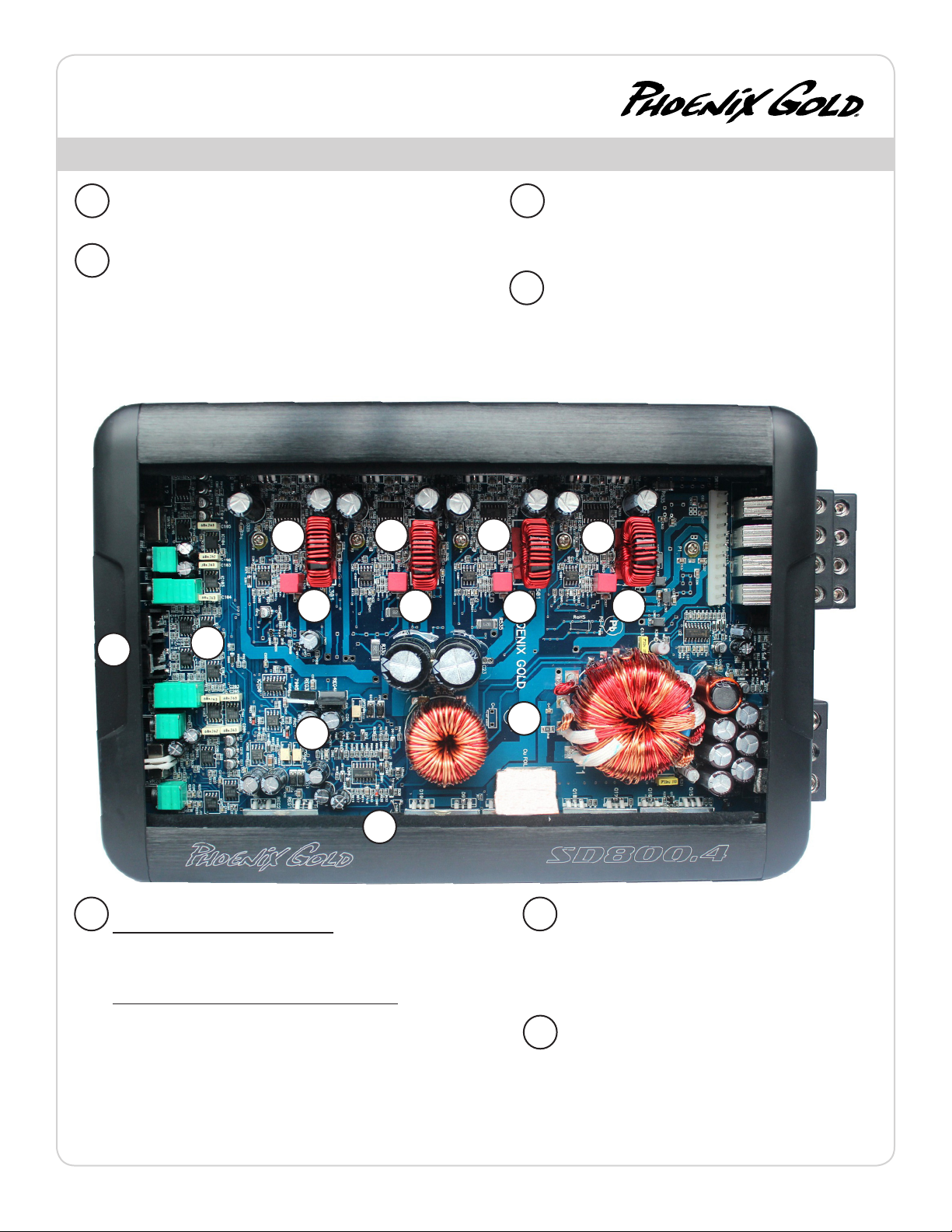
Key Features
BALANCED DIFFERENTIAL INPUTS
A
Provides maximum rejection of unwanted noise from upstream
components.
AUDIOPHILE NJM2068M OP-AMPS
B
Most mobile ampliers today use the standard NJM4558 op-amp which
has a bandwidth of 3MHz, slew rate of 1V/uSec and noise level of 1.4uV.
The NJM2068M is simply a better performer with a bandwidth of 19MHz,
slew rate of 6V/uSec and noise level of .44uV.
The result is quieter, faster and wider bandwidth performance that
ensures the original music material is reproduced as accurately as
possible.
C
D
C
D
C
ULTRA HIGH SPEED IR CLASS D CHIPSET
C
State of the art IR20957 chipset switches at more than 300kHz
for blistering audio performance. All four or ve chipsets are
sync’d together in unison to eliminate unwanted harmonics or
distortion.
POST FILTER FEEDBACK
D
Feedback is when part of the output signal is “fed back” into the
original signal to ensure stability and accurate sound. Class D
ampliers use output lters (see the 4 vertical coils below), but
most DO NOT INCLUDE these lters in the feedback loop. SD
ampliers INCLUDE or take feedback after its passed through
these lters. The result is more accurate sound that rivals some
of the best class A/B ampliers.
C
D
D
A
B
G
E
F
ADAPT POWER MANAGEMENT SYSTEM
E F
Full power output from 11 to 15 volts: ADAPT delivers the same output
power regardless of the vehicle’s electrical system voltage. Instantaneous or
long term voltage drops have no eect on the amplier’s power output. This
means more dynamic and less distorted audio output.
Dual power modes provide maximum efficiency: ADAPT seamlessly
optimizes the power supply and Class D operating circuitry by adapting to
the end user’s listening habits. When the ADAPT circuit senses lower signal
levels, it will automatically optimize the amplier’s power supply and Class
D circuitry to a low power mode that maximizes eciency and minimizes
heat to almost zero. As a signal increase is detected the amplier instantly
shifts into a high power mode, where the power supply and Class D sections
are now optimized to deliver massive power and headroom for those
demanding listening sessions. The amplier is constantly monitoring and
adapting between these modes which results in higher overall eciency,
much lower operating temperatures and rock solid reliability.
G
THERMAL ROLLBACK CIRCUIT
Under most conditions, SD ampliers generate moderate
to low heat. However, if extreme conditions exist, as
temperatures rise the amplier will automatically adjust the
power output, so your music continues to play. These changes
are inaudible and vastly reduce the chance for any thermal
shutdown events.
LOW EMI CIRCUIT BOARD DESIGN
Most class D ampliers can emit EMI noise that can cause
problems with AM/FM reception or other devices in the
vehicle. SD ampliers have undergone intense real world
engineering and testing to vastly reduce or eliminate these
issues. Careful PCB layout using four layers (most ampliers
feature just two) along with many key lters ensures a very
low possibility of any interference issues.
www.phoenixgold.com
Page 4
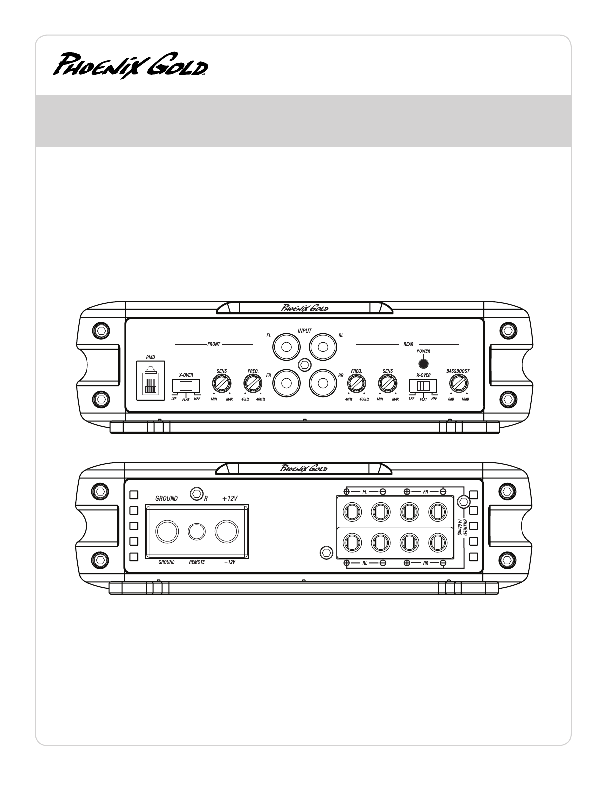
SD800.4
4 Channel Power Amplifier
Amplier Owner’s Manual
FRONT AND REAR INPUTS
Connect preamp signal cables from headunit to these inputs. The front
AND rear inputs must be used, if only the front input is used then the rear
speaker outputs will have no output signal.
CROSSOVER FREQUENCY
Controls the crossover point for the speaker outputs.
BASS BOOST
Variable bass boost from 0 to +18dB @ 45Hz.
SENS
Used to reach maximum amplier power with a wide variety of headunits.
CONFIG
FLAT: Crossovers are turned o
HP: High pass crossover is on
LP: Low pass crossover is on
+12V
This must be connected to the fused positive terminal (+12V) of the car’s
battery. The fuse must be located within 18 inches of the battery.
REMOTE
This must be connected to switched +12V, usually a trigger wire coming
from the head unit or ignition.
GROUND
This must be connected to the negative terminal of the car’s battery or
bolted to a clean, unpainted part of the chassis of the vehicle.
www.phoenixgold.com
REMOTE MONITORING DISPLAY (RMD)
Connect optional RMD Voltage Display to this port.
SPEAKER OUTPUTS
Used to connect the amplier to speakers. SD800.4’s minimum
impedance is 4 ohms bridged or 2 ohms stereo. Use the Left + and
Right - to bridge the channels.
Page 5

Amplier Owner’s Manual
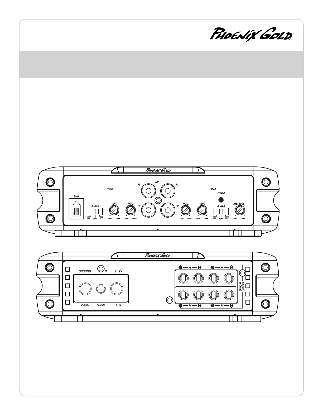
SD1100.5
5 Channel Power Amplifier
FRONT, REAR AND SUB INPUTS
Connect preamp signal cables from headunit to these inputs.
SUB INPUT SWITCH
Determines which input will feed signal to the subwoofer channel.
“IN” or SUB = Use the Sub Input
“OUT” or F/R = Use the Front and Rear inputs as its signal will be summed
then sent to the sub channel of the amplier.
HPF/LPF CROSSOVER FREQUENCY
Controls the crossover point for the speaker outputs.
SENS
Used to reach maximum amplier power with a wide variety of headunits.
BASS BOOST
Variable bass boost from 0 to +18dB @ 45Hz.
REMOTE BASS LEVEL CONTROL (RBCF)
This port is for connecting the remote subwoofer level control. This allows up to
20dB of volume adjustment for the subwoofer channel. This is not a bass boost, it
controls the level of the low pass signal.
NOTE: This control is not compatible with the Phoenix Gold LPL44 level control.
+12V
This must be connected to the fused positive terminal (+12V) of the car’s
battery. The fuse must be located within 18 inches of the battery.
REMOTE
This must be connected to switched +12V, usually a trigger wire coming
from the head unit or ignition.
GROUND
This must be connected to the negative terminal of the car’s battery or
bolted to a clean, unpainted part of the chassis of the vehicle.
REMOTE MONITORING DISPLAY (RMD)
Connect optional RMD Voltage Display to this port.
SPEAKER OUTPUTS
Used to connect the amplier to speakers. SD1100.5’s minimum
impedance is 4 ohms bridged or 2 ohms stereo on front and rear
channels. Use the Left + and Right - to bridge the channels. Minimum
impedance is 2 ohms for the subwoofer channel and its not bridgeable.
www.phoenixgold.com
Page 6

System tuning
1. Install all system fuses.
2. Set the amplier’s input sensitivity controls to their minimum positions
(full counterclockwise).
3. Set all amplier crossover switches according to your system’s design.
4. Make preliminary adjustments to the crossover frequency, usually 80Hz
is good starting point for high and low pass. It may be necessary to ne
tune the crossover frequency later for the best overall sound quality.
5. If using a Remote Subwoofer Level Control, set it to maximum (full
clockwise).
6. Turn the headunit on with the volume set to minimum.
7. Visually check the amplier’s has turned on by the power LED.
8. Check the condition of all other components to make sure they are
powered up.
9. Set the headunit’s tone controls, balance, and fader to the center (at)
position. Turn o any loudness or other signal processing features.
10. Set the volume control of the headunit to 3/4 of maximum volume. Play
music you typically listen to through the system.
11. Turn up the sensitivity or input level control on the amplier until the
speakers reach maximum undistorted output.
Amplier Owner’s Manual
12. Repeat sensitivity level adjustments for all other ampliers.
13. Reduce the headunit’s volume to a comfortable level.
14. Listen to various musical selections to check overall system balance.
Compare front to rear, midbass to midrange, etc. If one speaker set is
too loud compared to another, then its level must be lowered to blend
correctly with the other speakers.
15. Fine tune crossover frequencies to achieve the smoothest possible
blending of each speaker set.
16. Adjust the Bass Equalization Controls on the amplier, headunit or
processor upstream if necessary to increase output.
Note: Use these controls sparingly. Every 3dB of boost requires double the
power at 45Hz. If your subwoofer system requires a lot of boost to sound
good, there may be a problem. Look for out-of-phase woofers, a leaking
subwoofer box, or incorrect box size.
17. With all levels set correctly, the system will reach overall maximum
undistorted output at the volume level set in step 10.
TROUBLESHOOTING
NO POWER:
Check voltage at the amplier with a DMM (volt meter), +12v and R
(with head unit on) the voltage should register between 11.5V and
14.4V when using the attached ground lead of the amplier. Check
fuse at the battery. Use a meter to verify connection from one end
of the fuse to the other, breaks may not always be visible. If the fuse
is blown, check the power wire and also the amplier for a short. If
the short is in the amplier itself, see your Phoenix Gold dealer. If a
short is not present, replace the fuse.
POWER WITHOUT SOUND:
Turn the amplier o and check all input and output signal cables
and power connections. Check the speakers for shorts with a DMM
(volt meter) or by connecting them to another audio source. After
making sure everything is correct, turn the amplier on again.
NO SOUND FROM ONE OR MORE CHANNELS:
Check the balance control in the head unit. Check speaker
connections. Check signal input connection. Very low output: Check
your head unit’s fader control or the amplier’s input sensitivity
level.
FREQUENT AMPLIFIER SHUTDOWN WITH AUTOMATIC
RECOVERY:
This indicates chronic amplier thermal shutdown because
of operation at consistently high internal temperatures. High
operating temperature can be caused by inadequate ventilation.
Make sure you are not running a lower than recommend
impedance. Also check for damaged speakers or passive crossover
systems. Finally, chronic thermal shutdown may result from
otherwise normal operation of the amplier at elevated output
power levels, which can be resolved by providing additional
amplier cooling, installing a higher-power amplier, or reducing
amplier output level.
POWER CYCLES ON/OFF QUICKLY:
The power indicator going o repeatedly when the audio system is
on. Check the amplier’s connection to the battery. Check battery
voltage. If low, recharge or replace the battery. Check all ground
connections.
www.phoenixgold.com
Page 7
Manual del Amplicador
SD800.4
Amplificador de Potencia de 4 Canales
ENTRADAS DELANTERA y TRACERA
Conectar cables de señal de preamp del radio a estas entradas. Ambas
entradas, Front y Rear deben ser usadas, si solo se usa el Front no habrá
señal en el Rear output.
FRECUENCIA de CROSSOVER
Controla el nivel de frecuencia de crossover.
BASS BOOST
Bajo variable de 0 a +18dB @ 45Hz.
SENS
Usado para alcanzar el máximo poder amplicado con una gran variedad de
radios.
CONFIGURACION
FLAT: El crossover es o
HP: El crossover high pass es “on”
LP: El crossover low pass es “on”
+12V
Este debe ser conectado al fusible del terminal positivo (+12V) de la
batería del auto. El fusible debe ser ubicado a menos de 18 pulgadas de
la batería.
REMOTO
Este debe ser conectado al shwich +12V. Usualmente al cable de gatillo
que viene del radio o del encendido.
TIERRA
Este debe ser conectado al terminal negativo de la batería del auto o a
una parte limpia y sin pintura del chasis del auto.
DISPLAY PARA MONITOREO REMOTO (RMD)
Conectar el display de voltaje opcional RMD a este puerto.
SALIDA de PARLANTES
Usado para conectar los parlantes. La mínima impedancia para el SD800.4
es 4 ohms o 2 ohms estéreo. Usar Left+ y Right – para el bridge.
www.phoenixgold.com
Page 8

SD1100.5
Amplificador de Potencia de 5 Canales
Manual del Amplicador
ENTRADAS
Conectar cables de señal de preamp del radio a estas entradas. Las
entradas frontales, traseros y sub debe ser utilizado. Si una entrada no se
utiliza no habrá salida para ese conjunto de canales.
HPF/LPF FRECUENCIA de CROSSOVER
Controla el nivel de frecuencia de crossover.
SUB SELECCION DE ENTRADE
Determina qué entrada se alimenta la señal en el canal de subwoofer.
“IN” o SUB = Usar la entrada Sub
“OUT” o F / R = Usa el frontal y las entradas traseras que su señal se
sumarán luego enviado a la sub canal del amplicador.
SENS
Usado para alcanzar el máximo poder amplicado con una gran variedad de
radios.
BASS BOOST
Bajo variable de 0 a +18dB @ 45Hz.
CONTROL REMOTO de NIVEL de BAJOS
Este puerto es para conectar el control de nivel de bajos. Esto permite un
ajuste de hasta 20dB de volumen. Este no es un bass bost, este controla el
nivel de low pass signal.
NOTA: Este control no es compatible con el control de nivel Phoenix Gold
LPL44.
+12V
Este debe ser conectado al fusible del terminal positivo (+12V) de la
batería del auto. El fusible debe ser ubicado a menos de 18 pulgadas de
la batería.
REMOTO
Este debe ser conectado al shwich +12V. Usualmente al cable de gatillo
que viene del radio o del encendido.
TIERRA
Este debe ser conectado al terminal negativo de la batería del auto o a
una parte limpia y sin pintura del chasis del auto.
www.phoenixgold.com
DISPLAY PARA MONITOREO REMOTO (RMD)
Conectar el display de voltaje opcional RMD a este puerto.
SALIDA de PARLANTES
Usado para conectar los parlantes. La mínima impedancia para el
SD1100.5 es 4 ohms o 2 ohms estéreo. Usar Left + y Right – para el bridge.
Impedancia mínima es de 2 ohms para el canal de subwoofer y no es
bridgeable.
Page 9

Manual del Amplicador
INSTALLATION NOTES:
1. Instalar todos los fusibles del sistema
2. Ajustar los controles de sensibilidad (input sensibility controls) del
amplicador a la posición mínima(Contra reloj)
3. Ajustar todos los switches de crossover de acuerdo al diseño de
su sistema.
4. Hacer los ajustes preliminares a la frecuencia del crossover,
usualmente 80Hz es un buen punto de partida para high y low pass.
Pudiera ser necesario luego ajustar la frecuencia del crossover para
obtener la mejor calidad de sonido.
5. Si se usa un control remoto del nivel de subwoofer, ajustarlo al
máximo (en sentido del reloj)
6. Encienda el radio con el volumen ajustado al mínimo
7. Visualmente chequear que el amplicador se haya encendido, ver
el power LED
8. Chequear que todos los demás componentes estén encendidos
9. Ajustar los controles de tonos del radio, balance y fader en la
posición del medio. Apagar cualquier loudness u otro botón de
proceso de señal.
10. Ajustar el volumen del radio al máximo sin distorsión (en la
mayoría de los radios el volumen máximo sin distorsión es 3 u 4) Use
una grabación clara y dinámica.
11. Suba la sensibilidad o el nivel de control de entrada en el
amplicador hasta que los parlantes alcancen el mayor output sin
distorsión.
SISTEMA TUNING
12. Repita los ajustes de niveles de sensibilidad para todos los otros
amplicadores.
13. Reduzca el volumen del radio al nivel más confortable.
14. Escuche varias diferentes selecciones de música para chequear
el balance general del sistema. Compare front y rear, midbass y
midrange, etc. Si un parlante suena muy fuerte con respecto al otro,
su nivel debe ser disminuido para obtener un buen balance.
Nota: Para los subwoofers controlados por el control de nivel
remoto, mantener el nivel del paso 11 o 12. Use el control para
mezclar los subwoofers con el resto del sistema. El volumen correcto
del subwoofer cambiara dependiendo del ruido en el ambiente,
carretera y las diferencias en las grabaciones.
15. Anación del ajuste de frecuencias de crossover para obtener la
mejor mezcla posible de cada set de parlantes.
16. Ajuste de los controles de ecualización de bajos en el
amplicador, radio o procesador si es necesario aumentar el output. .
Nota: Use los controles prudentemente. Cada incremento de 3dB
requiere el doble de poder a 45Hz. Si su sistema de subwoofer
requiere mucho aumento para un mejor sonido, probablemente
exista un problema. Fíjese si los subwoofers están out-of-phase, hay
escape en el cajón del subwoofer, o el tamaño del cajón es incorrecto
17. Con todos los niveles ajustados correctamente, el sistema
alcanzara el máximo output sin distorsión al nivel de volumen
ajustado en el paso 10.
Corrección de problemas
No poder: Chequear el voltaje al amplicador con un DMM (voltímetro). +12v
y R (con el radio encendido) el voltaje debería ser entre 11.5V y 14.4V cuando
se usa la tierra del amplicador. Chequear el fusible del amplicador y la
batería. Vericar la conexión desde un nal del fusible hasta el otro con un
meter, a veces las rupturas no son visibles. Si el fusible está quemado, chequear
el cable de poder y también el amplicador por un corto. Si el corto es en el
amplicador, llévelo a su agente autorizado Phoenix Gold. Si no hay corto, solo
reemplace el fusible.
Poder pero no sonido: Apague el amplicador y chequee todos los cables de
señal de entrada y salida, y las conexiones de poder. Chequear los parlantes
para ver si hay corto con un DMM (voltímetro) o conectándolos a otra fuente
de sonido. Luego de chequear que todo este correcto puede encender el
amplicador.
No sonido de uno o más canales: Chequear por exceso de voltaje en los
terminales de +12V y tierra. Chequear el control de balance del radio. Chequear
las conexiones de los parlantes. Chequear la conexión de señal de input.
Muy bajo output: Chequear el control de fader del radio o el nivel de
sensibilidad de input del amplicador. Asegurarse que el control de frecuencia
subsónica no esté demasiado alto y el control de frecuencia LP no esté muy
bajo al mismo tiempo.
Frecuentes apagados del amplicador con reencendido automáticamente:
Este indica apagado crónico del amplicador por constante operación a
alta temperatura interna. Operación a alta temperatura puede ser causa de
inadecuada ventilación. Asegúrese que no está operando a una impedancia
menor a la recomendada. También chequee por daños en los parlantes, o
passive crossover. Finalmente, apagados térmicos crónicos pueden ser el
resultado de otras operaciones normales del amplicador a elevados niveles
de output, lo cual puede ser solucionado previendo adicional enfriamiento al
amplicador, instalando un amplicador de alto poder o reduciendo el nivel
de output.
“Motor Boating” – El indicador de poder se apaga repetitivamente cuando el
sistema esta encendido: Chequear la conexión del amplicador a la batería.
Chequear el voltaje de la batería. Si es bajo, recargar o reemplazar la batería.
Chequear las conexiones de tierra.
www.phoenixgold.com
Page 10

SD800.4
amplificateur de puissance
Manuel de l’amplicateur
ENTRÉE
Reliez les câbles de signal préampli de l’unité principale sur ces bornes.
FRÉQUENCE DE FILTRE PASSIF PASSE-BAS et
PASSE-HAUT
Contrôle les points de ltre pour les sorties du haut-parleur.
AMPLIFICATION DES BASSES
Amplication des basses variable de 0 à +18 dB à 45Hz.
NIVEAU
Sert à atteindre une puissance d’amplicateur maximale avec une grande variété
d’unités principales.
CONFIG
FLAT : Croisé est éteint.
HP : L’haute passe croisée est sur.
LP : Le niveau bas passe croisé est sur.
+12V
Doit être relié à la borne positive protégée par fusible (+12 V) de la batterie
de la voiture. Le fusible doit être situé à moins de 18 pouces de la batterie.
BORNE TÉLÉCOMMANDE
Doit être relié à la borne +12 V commutée, généralement un l d’amorçage
sortant de l’unité principale ou de l’allumage.
MASSE
Doit être relié à la borne négative de la batterie de la voiture ou boulonné
sur un élément propre et non peint du châssis du véhicule.
www.phoenixgold.com
ENTRÉE DE L’AFFICHAGE DE TENSION A DISTANCE (RMD)
Connectez le RMD d’achage de tension facultatif à cette prise jack.
SORTIES ENCEINTES
Utilisé pour connecter l’amplicateur aux enceintes. SD800.4 impédance
minimale est de 4 ohms ponté ou stéréo 2 ohms.
Page 11

Manuel de l’amplicateur
SD1100.5
amplificateur de puissance
ENTRÉE
Reliez les câbles de signal préampli de l’unité principale sur ces bornes.
FRÉQUENCE DE FILTRE PASSIF PASSE-BAS et
PASSE-HAUT
Contrôle les points de ltre pour les sorties du haut-parleur.
AMPLIFICATION DES BASSES
Amplication des basses variable de 0 à +18 dB à 45Hz.
NIVEAU
Sert à atteindre une puissance d’amplicateur maximale avec une grande variété
d’unités principales.
COMMANDE À DISTANCE DU NIVEAU DES BASSES
Ce port sert à connecter la télécommande de niveau. Cela permet un ajustement du
volume allant jusqu’à 20 dB. Ce n’est pas une amplication des basses mais permet de
contrôler le niveau du signal du ltre passe-bas.
+12V
Doit être relié à la borne positive protégée par fusible (+12 V) de la batterie
de la voiture. Le fusible doit être situé à moins de 18 pouces de la batterie.
BORNE TÉLÉCOMMANDE
Doit être relié à la borne +12 V commutée, généralement un l d’amorçage
sortant de l’unité principale ou de l’allumage.
MASSE
Doit être relié à la borne négative de la batterie de la voiture ou boulonné
sur un élément propre et non peint du châssis du véhicule.
ENTRÉE DE L’AFFICHAGE DE TENSION A DISTANCE (RMD)
Connectez le RMD d’achage de tension facultatif à cette prise jack.
SORTIES ENCEINTES
Utilisé pour connecter l’amplicateur aux haut-parleurs. SD1100.5 impédance d
‘minimum est de 4 ohms ponté ou 2 ohms stéréo.
SÉLECTION D’ENTRÉE SUB
Détermine quelle source sera signal de nourrir le canal de subwoofer.
“IN” ou SUB = utiliser l’entrée Sub
“OUT” ou F / R = Utilisez le Front et les entrées arrières comme son signal seront
additionnées puis envoyé à la sous-canal de l’amplicateur.
www.phoenixgold.com
Page 12

Phoenix Gold
A Division of AAMP of America™
13190 56th Court
Clearwater, Florida 33760
P: 888-228-5560
info@phoenixgold.com
www.phoenixgold.com
© 2013 AAMP of Florida, Inc
Designed and Engineered in the USA
LIMITED WARRANTY ON AMPLIFIERS
Phoenix Gold warrants this product to be free of defects in materials and workmanship for a period of one (1) year from the original date of purchase. This
warranty is not transferable and applies only to the original purchaser from an authorized Phoenix Gold dealer in the United States of America only. Should service
be necessary under this warranty for any reason due to manufacturing defect or malfunction, Phoenix Gold will (at its discretion), repair or replace the defective
product with new or remanufactured product at no charge. Damage caused by the following is not covered under warranty: accident, misuse, abuse, product
modication or neglect, failure to follow installation instructions, unauthorized repair attempts, misrepresentations by the seller. This warranty does not cover
incidental or consequential damages and does not cover the cost of removing or reinstalling the unit(s). Cosmetic damage due to accident or normal wear and
tear is not covered under warranty.
INTERNATIONAL WARRANTIES:
Products purchased outside the United States of America are covered only by that country’s Authorized Phoenix Gold reseller and not by Phoenix Gold. Consumers
needing service or warranty information for these products must contact that country’s reseller for information.
 Loading...