

Phoenix Gold SAM100, SAM200 Owner's Manual
INNOVATIVE HOME
Smart Audio Management (SAM)
SAM100 and SAM200 Speaker Distribution & Impedance Matching Centers
The SAMs distribute one speaker-level stereo signal to 6 stereo or 12 mono listening zones (SAM100), or to
12 stereo or 24 mono listening zones (SAM200). Use the optional SAMBB1 24kt Gold-Plated copper bussbars for mono operation.
Features
• UL and CSA style 16 gauge white powder-coated steel cabinets with cable knockouts on all four sides and
removable vented cover plates
• Cover plate attaches with easy-to-use white, push-lock studs
• Manually adjustable power resistor taps (4 to 0.1Ω) allow for accurate setting of system impedance
• PC board mounted input terminals rated at 30 amps accept up to 8 gauge spade terminals
• Offset angled output terminals rated at 15 amps accept up to 12 gauge cable directly
• UL/CSA-approved snap-in strain reliefs (six for SAM100, twelve for SAM200)
• On-board socket accepts the optional HDB1 Doorbell Interrupt Module for momentary system muting
• On-board expansion socket allows individual zone switching either directly from the SAM panel with the
optional SM6 On-site Switcher or remotely with the RM4 / RM6 Relay Module and the HJRS / HRZS
Remote Switching Module.
Installation Precautions
The SAMs come with the power resistors set to the 4 ohm position. This setting presents each amplifier
channel with a 5.33 ohm impedance (SAM100) or a 4.67 ohm impedance (SAM200) with all zones
connected to 8 ohm speakers. We do not recommend changing the adjustment unless your amplifier can
handle a lower impedance or you are not using all zones.
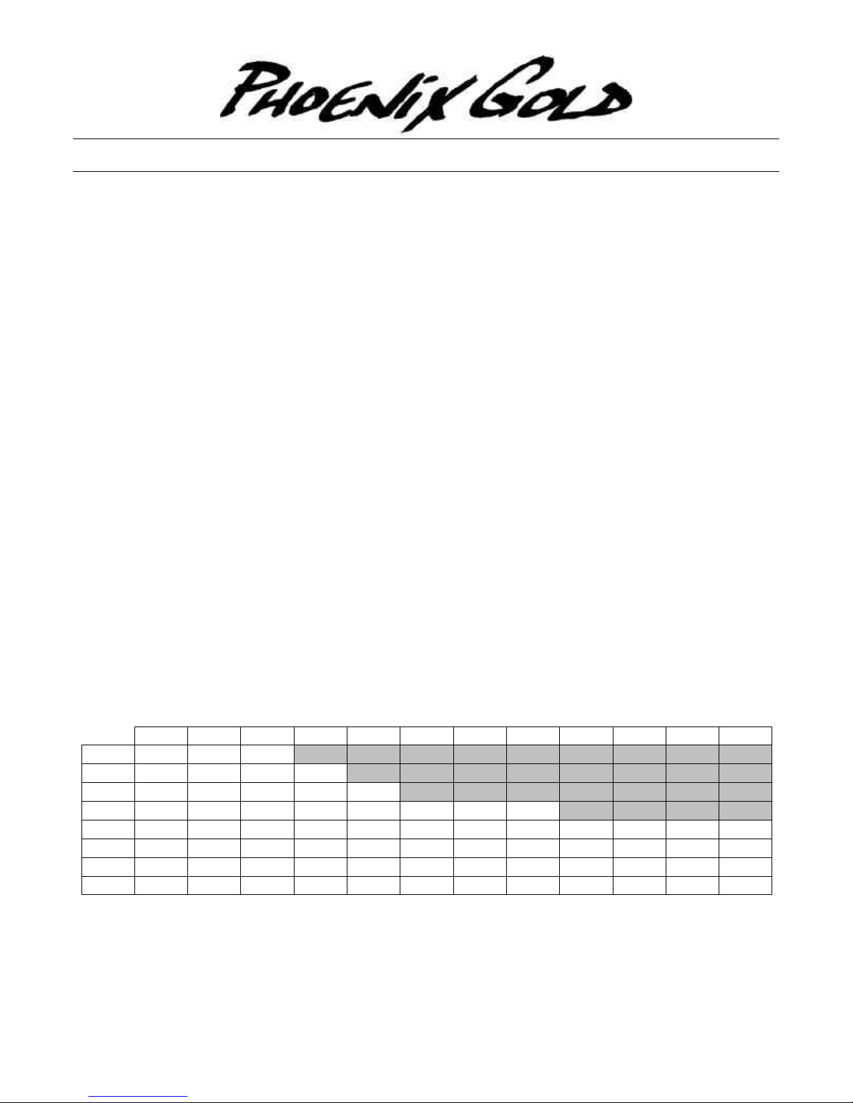
The table below indicates the impedance each amplifier channel sees with varying resistor settings on the left
versus the number of active zones across the top. The shaded areas indicate an impedance of less than 3
ohms and should be avoided. For mono operation, the impedance seen by the amplifier is half of the indicated
value.
1 2 3 4 5 6 7 8 9 10 11 12
0.5
1
1.5
2
2.5
3
3.5
4
Dimensions, Box, SAM100 / SAM200, H x W x D.......................................................................................12” x 10” x 3” / 12” x 13” x 3”
Dimensions, Cover, SAM100 / SAM200, H x W x D...........................................................................14” x 12” x .05” / 14” x 15” x .05”
One Phoenix Gold Way l 9300 North Decatur l Portland, OR 97203 l Tel: 503.288.2008 l Fax: 503.978.3380
PG Tech Support 4/98 8100.0152A
8.50 4.50 3.17 2.50 2.10 1.83 1.64 1.50 1.39 1.30 1.23 1.17
9.00 5.00 3.67 3.00 2.60 2.33 2.14 2.00 1.89 1.80 1.73 1.67
9.50 5.50 4.17 3.50 3.10 2.83 2.64 2.50 2.39 2.30 2.23 2.17
10.00 6.00 4.67 4.00 3.60 3.33 3.14 3.00 2.89 2.80 2.73 2.67
10.50 6.50 5.17 4.50 4.10 3.83 3.64 3.50 3.39 3.30 3.23 3.17
11.00 7.00 5.67 5.00 4.60 4.33 4.14 4.00 3.89 3.80 3.73 3.67
11.50 7.50 6.17 5.50 5.10 4.83 4.64 4.50 4.39 4.30 4.23 4.17
12.00 8.00 6.67 6.00 5.60 5.33 5.14 5.00 4.89 4.80 4.73 4.67
Phoenix Gold International, Inc.
9
1 2
8
IN T
CTRL
LEFT RIGHT
_
+
INTERFACE
1 2
4
6
0
3 4
1
5 6
2
7 8
3
9 10
5
11 12
4
7
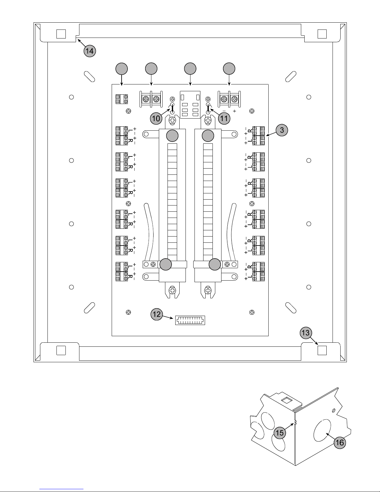
1. Left Amplifier Input
2. Right Amplifier Input
3. Numbered Speaker Output Zone
4. Left Channel Power Resistor
5. Adjustable Left Channel Resistance A djustment Tap
6. Right Channel Power Resistor
7. Adjustable Right Channel Resistance Adjustment Tap
8. Interface Socket for Optional HDB1 Door Bell Interrupt Module
9. HDB1 Interrupt Control Terminal for Switched 12 - 16 V AC Door Bell Signal
10. Left Channel Interface Socket Bypass Jumper. Cut when using the HDB1
11. Right Channel Interface Socket Bypass Jumper. Cut when using the HDB1
12. Expansion Socket for Optional Zone Switching Modules (See Features)
13. Mounting Tab for the Cover Mounting Push-lock Receptacles
14. Speaker Wire Stripping Guide
15. 1/2” and 5/8” Drywall Alignment Markers
16. Wiring Knockout for the Supplied Snap-in Strain Reliefs
EXPANSION PORT
 Loading...