

Page 1
• One-of-a-kind carbon fiber cosmetic finish forms the unique racing theme.
• Limited production of the amplifier ensures it as a collector's item for years to come.
• Large capacitor bank built-in on the rail voltage to allow for unmatched internal voltage stiffing
during demanding musical dynamics.
• Built-in Basscube allows 15 dB of parametric boost and subsonic filter for low pass section of
the amplifier.
• TCCH™ Thermal Convection Cooled Heatsink. This proprietary design uses two variable speed
fans to ensure that the Octane keeps its cool when the music gets hot!
• High-current Triple Darlington output stage. This tried and true topology is the standard for
outstanding dynamic peak output performance.
• TAIM™ Timed Acoustically Integrated Muting. Insures dead silent turn on & off, no clicks, pops
or buzzes.
• 24dB per octave, high pass and low pass crossover. Continuously variable from 40Hz to 800Hz.
• Twin-T™ bass boost circuit provides up to 18dB of boost at 45Hz.
• Superbrite™ Tri-LED power-on indicator.
• Optional LPL44™ Low Pass Level controller allows the driver to adjust bass volume from the
driver's seat.
• Optional RDDP™ Remote Diagnostic Display Panel allows the driver to monitor the amplifier's
battery voltage, power-on, thermal and overload status with use of the SDT™ or RDDP™ kit.
Page 2
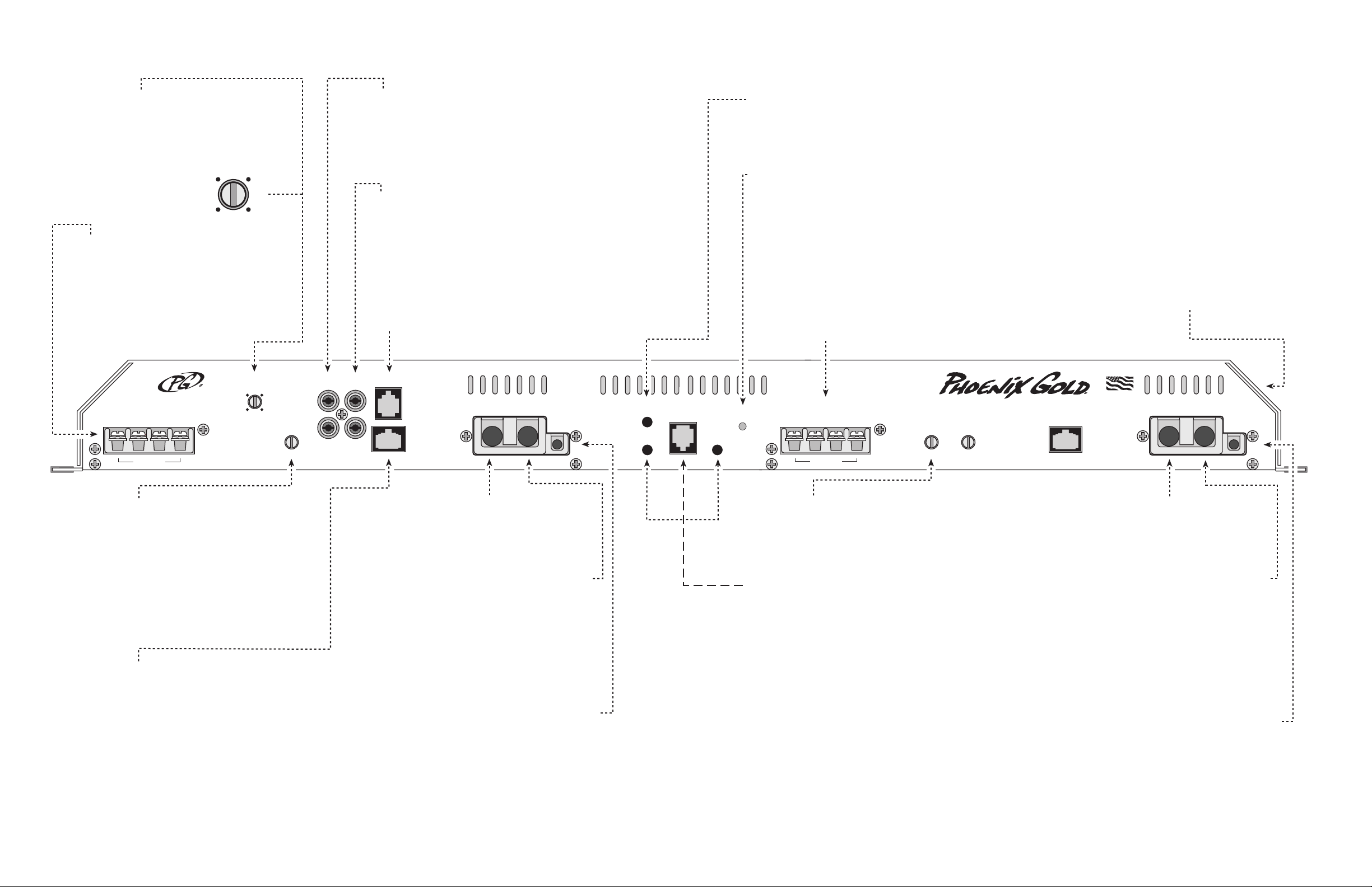
CROSSOVER FREQUENCY Controls the high
and low pass crossover point symetrically for
the high and low pass speaker outputs. The
crossover is always engaged with a frequency
adjustable from 40Hz to 800Hz with a 24dB
per octave slope.
160 300
80040
INPUTS Connect preamp signal cables from
the headunit to these terminals. To maximize
noise rejection, we recommend using Phoenix
Gold ZEROpoint Musical Reference, ZEROpoint
Pro, ZEROpoint QLX, ZEROpoint TRX, XS560
or XS460 series twisted pair interconnects.
BYPASS OUTPUTS Provides a full range
signal for an additional amplifier or signal
processor. The output is always Full Range.
STEREO/MONO SWITCH The low pass
section of the amplifier will receive a mono
signal when the button is set to the IN position
and a stereo signal when set to the OUT
position.
LOW PASS POWER LED When lit the low
pass section of the amplifier is on indicating
it is grounded through the B- terminal and is
receiving voltage through the B+ and remote
turn-on terminals.
STATUS LEDS
BLUE: Three SuperbriteTM blue LEDs on top of
the amplifier light when the high pass section of
the amplifier is turned on indicating it is grounded
through the B- terminal and is receiving voltage
through the B+ and remote turn-on terminals.
YELLOW: Lights if the amplifier shuts down due
to overheating. If the internal heatsink reaches
115 degrees Celsius, the amplifier shuts down
and continues to run the fan at high speed until
the internal temperature falls below 115 degrees.
HIGH PASS SPEAKER OUTPUTS Used
to connect the high pass section of the amplifier
to speakers. Use the left + and right - terminals
for bridged mode. Minimum speaker cable
size is 16 gauge (PG# SS162 or QS162). Use
12 Gauge for bridged operation (SS122 or
QS122). Minimum impedance is 2 ohms
bridged or 1 ohm stereo.
FREQ
160 300
HIGH PASS SPEAKER
+ -
R+L+ L-
BRIDGED
R-
80040
INPUT SENSITIVITY This control adjusts
the amplifier’s sensitivity to incoming signals.
Clockwise increases sensitivity.
Counterclockwise decreases sensitivity. Higher
signal levels allow for a lower sensitivity setting
and lower overall noise floor. Lower signal
levels will require increased sensitivity to reach
full power. To maximize performance, we
recommend using a PLD1 Professional Line
Driver or its equivalent. The High and Low
Pass sections have seperate sensitivity levels.
REMOTE DIAGNOSTIC DISPLAY PORT
This port is for connecting the optional RDDP
or SDT remote monitoring kit. The RDDP
display indicates the amplifier's condition and
voltage with tri-color LEDs. While the SDT
includes a DC voltmeter and a tri-color status
LED.
SENS
6 .2
LOW PASS SPEAKER OUTPUTS Used to
LPL CONTROL PORT This port is for
connecting the optional LPL44TM Remote
Lowpass Level Control knob. The LPL44
TM
allows up to 20dB of subwoofer volume
adjustment from the driver's seat of the low
pass section of the amplifier.
BYPASS
OUTPUT
INPUT
L
R
LPL
RDDP
B–
POWER
LOW PASS
B+
R
STEREO/MONO
Q SELECT
REMOTE
CONTROL
SUBSONIC
FILTER
B- TERMINAL (CHASSIS GROUND)
Connect to a clean, solid chassis ground.
Remove all paint and dirt from the chassis
connection point. Minimum cable size is 4
gauge. Keep the cable as short as possible.
B+ TERMINAL (BATTERY POSITIVE)
Connect directly to the positive battery terminal.
Minimum cable size is 4 gauge. Remember
to properly fuse the High Pass B+ input cable
within 18 inches of the amplifier and positive
battery terminal.
connect the amplifier to low pass speakers.
Use the left + and right - terminals for bridged
mode. Minimum speaker cable size is 16
gauge (PG# SS162 or QS162). Use 12 Gauge
for bridged operation (SS122 or QS122).
Minimum impedance is 2 ohms bridged or 1
ohm stereo.
LOWPASS
POWER
LOW PASS SPEAKER
+ -
R+L+ L-
BRIDGED
R-
TWIN-TTM BASS EQ This control allows
up to 18dB of boost at 45Hz for the speaker
outputs. It cannot affect the bypass outputs.
Use this control sparingly. Every 3dB of
boost requires double the power at 45Hz.
BASS CUBE INPUT and CONTROLS
Connect the remote control unit for the bass
cube to the telephone style input. For more
information on the functions and specficiations
for setup and functions refer to the included
bass cube manual.
BASS
180 6 .2
SENS
Section Outputs Fuse size
High Pass 4 ohms stereo 50 amp
High Pass 2 ohms stereo 60 amp
High Pass 4 or 2 ohms bridged 60 amp
*Notes Prior to Installation: The bass cube will only effect the
low pass section of the amplifier. Both power terminals must be
RED: Lights if the amplifier shuts down due to
excessive output current. Common reasons for
excessive output current are chafed speaker cables
touching the vehicle’s chassis, speaker leads
touching each other or a damaged speaker voice
coil.
MADE IN AMERICA
RDDP
B–
POWER
B+
R
B- TERMINAL (CHASSIS GROUND)
Connect to a clean, solid chassis ground.
Remove all paint and dirt from the chassis
connection point. Minimum cable size is 4
gauge. Keep the cable as short as possible.
B+ TERMINAL (BATTERY POSITIVE)
Connect directly to the positive battery terminal.
Minimum cable size is 4 gauge. Remember
to properly fuse the High Pass B+ input cable
within 18 inches of the amplifier and positive
battery terminal.
Section Outputs Fuse size
Low Pass 4 ohms stereo 50 amp
Low Pass 2 ohms stereo 60 amp
Low Pass 4 or 2 ohms bridged 60 amp
wired to the appropriate sources for the both sections of amplifier
REMOTE TURN-ON TERMINAL Connect
to a switched 12 Vdc source such as the
headunit's “remote” or power antenna wire.
to operate correctly. The crossover for High and Low Pass speakers
is always activated. The internal capacitor bank automatically
charges and discharges, so there is no need for external charging.
REMOTE TURN-ON TERMINAL Connect
to a switched 12 Vdc source such as the
headunit's “remote” or power antenna wire.
Page 3

Continuous Output Power at 1% THD (watts):
Into 4 ohms Stereo @ 12.5 Vdc (IASCA/USAC) . . . . .37 x 4
Into 4 ohms Stereo @ 14.4 Vdc . . . . . . . . . . . . . . .100 x 4
Into 2 ohms Stereo @ 14.4 Vdc . . . . . . . . . . . . . . .200 x 4
Into 4 ohms Bridged @ 14.4 Vdc . . . . . . . . . . . . . .400 x 2
Minimum Speaker Load, Bridged . . . . . . . . . . . . . .2 ohms
Minimum Speaker Load, Stereo . . . . . . . . . . . . . . . .1 ohm
Chassis Dimensions . . . . . . . . . .13.00L x 29.00W x 2.50H
Overall Dimensions . . . . . . . . . . .13.00L x 30.00W x 2.50H
Bass Boost Center Frequency . . . . . . . . . . .20Hz to 110Hz
Bass Boost Characteristic, switch selected:
Wide . . . . . . . . . . . . . . . . . . . . . . . . . . . . . .Q = 2
Narrow . . . . . . . . . . . . . . . . . . . . . . . . . . . . . . .Q = 6
Bass Boost Level . . . . . . . . . . . . . . . . . . . . . . . . . .0 to 15dB
Subsonic Filter:
Slope . . . . . . . . . . . . . . . . . . . . . . .18dB per octave
Tracking Freq. . . . . . . .1/3 octave below Boost Freq.
Fixed Freq. . . . . . . . . . . . . . . . . . . . . . . . . . . . .25Hz
Typical Total Harmonic Distortion . . . . . . . . . . . . . .<0.02%
Signal to Noise Ratio (A-weighted) . . . . . . . . . . . . .>100dB
Frequency Response . . . . . . . . . . . .±1dB, 20Hz to 20kHz
Bass Boost . . . . . . . . . . . . . . . . . . . . .0 to +18dB @ 45Hz
Crossover Frequenty Range . . . . . . . . . . . .40Hz to 800Hz
Crossover Slope . . . . . . . . . . . . . . . . . . . .24dB per octave
Input Sensitivity . . . . . . . . . . . . . . .200 millivolts to 6 volts
Input Impedance . . . . . . . . . . . . . . . . . . . . . . .>30 kohms
Power Supply Operating Range . . . . .10.0 Vdc to 15.5 Vdc
Typical Current Draw at Idle . . . . . . . . . . . . . . . . .<3 amps
Phoenix Gold International, Inc. (or "Phoenix Gold")
warrants its products against defects in materials and
workmanship for a limited period of time.
For a period of one (1) year from date of original purchase,
we will repair or replace the electronic product, at our option,
without charge for parts and labor. The limited warranty
period is EXTENDED to three (3) years from date of original
purchase if the product was originally installed by an
authorized Phoenix Gold electronics dealer and accompanied
by a valid sales receipt showing a charge for installation.
Customer must pay all parts and labor charges after the
limited warranty period expires. The limited warranty period
for factory refurbished products expires after ninety (90) days
from date of original purchase. This limited warranty applies
only to purchases from authorized Phoenix Gold
Electronics/Speaker retailers.
This limited warranty is extended only to the original
purchaser and is valid only to consumers in the United
States. Consumers are required to provide a copy of the
original sales invoice from an authorized Phoenix Gold dealer
when making a claim against this limited warranty. This
limited warranty only covers failures due to defects in
materials or workmanship that occur during normal use. It
does not cover failures resulting from accident, misuse,
abuse, neglect, mishandling, misapplication, alteration, faulty
installation, modification, service by anyone other than
Phoenix Gold, or damage that is attributable to Acts of God.
It does not cover costs of transportation to Phoenix Gold or
damage in transit.
This warranty will become void if the serial number
identification has been wholly or partially removed, altered or
erased. Repair or replacement under the terms of this
warranty does not extend the terms of this warranty.
Should a product prove to be defective in workmanship or
material, the consumer's sole remedies will be repair or
replacement as provided under the terms of this warranty.
Under no circumstances shall Phoenix Gold be liable for loss
or damage, direct, consequential or incidental, arising out of
the use of or inability to use the product. There are no
express warranties other than described above.
Due to ongoing research and development, features,
specifications and availability are subject to change without notice.
9300 North Decatur
Portland, OR 97203
Tel: 503.286.9300
F ax: 503.978.3380
w w w.phoenixgold.com
8100.0176A
 Loading...