

Page 1
H
Twelve Channel Bridgeable Amplifier
with 4 Mode Buss System
Phoenix Gold International, Inc. • 9300 North Decatur Street • Portland, Oregon 97203
Tel: 503.286.9300 Fax: 503.978.3302
MX1260
User Manual
INNOVATIVE
Page 2
2
To prevent electric shock please read and follow all cautions
and instruction carefully.
WARNING: To reduce the risk of fire or electric shock,
do not expose this appliance to rain or moisture.
CAUTION: To reduce the risk of electric shock, do not
remove cover (or back); no user serviceable parts inside. Refer
servicing to qualified service personnel.
CAUTION: To prevent electric shock, match wide blade
of plug to wide slot, fully insert.
ATTENTION: Pour eviter les chocs electriques, introduire la
lame la plus large de la fiche dans la borne correspondante de
la prise et pousser jusqu'au fond.
AC Mains Fuse
MX1260 115-117VAC - 10A 250V Slo-Blo
MX1260 230-240VAC - 5A 250V Slo-Blo
IMPORTANT SAFETY INSTRUCTIONS
1. Read these instructions.
2. Keep these instructions.
3. Heed all warnings.
4. Follow all instructions.
5. Do not use this apparatus near water.
6. Clean only with a damp cloth.
7. Do not block any of the ventilation openings. Install
in accordance with the manufacturer’s instructions.
8. Do not install near any heat sources such as radiators,
heat registers, stoves, or other apparatus (including amplifiers) that produce heat.
9. Do not defeat the safety purpose of the grounding-type
plug. A grounding type plug has two blades and a third
grounding prong. The third prong is provided for your safety.
When the provided plug does not fit into your outlet, consult
an electrician for replacement of the obsolete outlet.
10. Protect the power cord from being walked on or pinched
particularly at plug, convenience receptacles, and the
point where they exit from the apparatus.
11. Only use attachments/accessories specified
by the manufacturer.
12. Use only with a cart, stand, tripod,
bracket, or table specified by the manufacturer, or sold with the apparatus. When a
cart is used, use caution when moving the
cart/apparatus combination to avoid injury
from tip-over.
13. Unplug this apparatus during lighting storms or when
unused for long periods of time.
14. Refer all servicing to qualified service personnel. Servicing
is required when the apparatus has been damaged in any
way, such as power-supply cord or plug is damaged, liquid
has been spilled or objects have fallen into the apparatus,
the apparatus has been exposed to rain or moisture, does
not operate normally, or has been dropped.
WARNING: To reduce the risk of fire or electric shock, do not
expose this apparatus to rain or moisture. The apparatus shall
not be exposed to dripping or splashing and that no objects
filled with liquids, such as vases, shall be placed
on the apparatus.
Safety Information
The lightning flash with arrowhead symbol, within
an equilateral triangle, is intended to alert the user
to the presence of uninsulated dangerous voltage
within the product's enclosure that may be of sufficient magnitude to constitute a risk of electrical
shock to persons.
The exclamation point within an equilateral triangle is intended to alert the user to the presence of
important operating and maintenance (servicing)
instructions in the literature accompanying the
appliance.
CAUTION
Risk of Electric Shock
Do Not Open
Page 3
3
MX 1260
Twelve Channel Bridgeable Amplifier
Using the Controls / Front Panel
Power
The front panel switch will manually switch the MX1260 on or
off. A blue LED behind the logo lens indicates its power status.
Whenever the amplifier’s power switch is in the “ON” position
the front panel lens is illuminated blue.
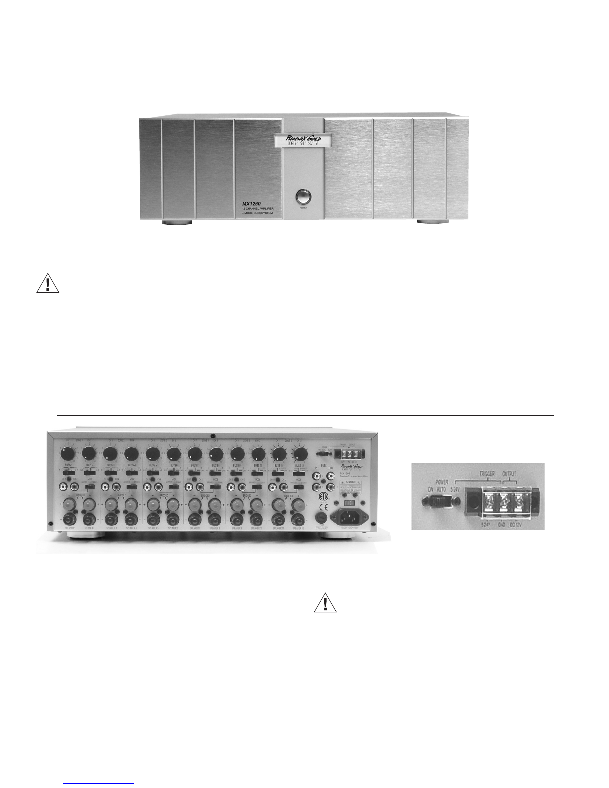
Using the Controls / Back Panel
Power
The MX1260 can be turned on and off independently via a
switch on the front panel, by signal sensing, or remotely by
a triggered DC input. There is a switch located on the upper
right rear of the amplifier to select how you would like to turn
on the MX1260 . If you would like to control the unit’s power on
/ power off status manually from the front, place the switch in
the “ON” position. If you would like to control the unit’s power
on / power off status by means of signal sensing, place the
switch in the “AUTO” position. If you would like to control the
unit’s power on / power off status by a DC remote trigger, place
If the Amplifier is “Active” while using the Signal Sensed power
or DC Triggered power function the clear ring around the power
switch is illuminated blue. If the amplifier is inactive in these
modes the ring around the power switch is not illuminated.
Congratulations on your purchase of the Innovative Home MX1260. Please take a few moments to read this entire manual,
and be sure to retain this document for future reference. Please read and observe all safety instructions detailed on page two (2).
Note:
If any part of this product is damaged or missing, please call your dealer
or Phoenix Gold Home Products directly at 800-435-7115 or 503-286-9300.
Note:
The front panel power switch must be in the “ON”
position for the 12V triggers or “Auto ON” features to operate.
the switch in the “5-24V” position, and connect the remote
triggering wire and ground from your triggering device to the
terminal labeled “TRIGGER (5-24V)” next to the switch.
You must also connect the ground terminal (GND) to ground for
the trigger circuit to be complete. A third terminal on the same
block is labeled “OUTPUT (DC 12V)”. This allows for remote turnon of other devices when the MX1260 is powered on. Please
read the owner’s manual for any devices you are attempting to
connect in this manner to ensure compatibility.
Page 4

4
Independent Volume Control
Each channel is able to control its volume independently relative
to the other channels. At the top of the rear panel, there are 12
black knobs which correspond to the volume level
of the channel identified by
a channel number above
it. The volume range is
labeled 0-10 and has 40
steps (clicks) from minimum to maximum output.
Rotate the knob clockwise
to increase output, and
counterclockwise to
decrease output.
BUSS Switches
Each channel (12 channels total) can be configured for any
of four different input sources. Below the volume knob is a four-
position switch to allow
the user to change these
configurations. The options
are listed above the switch
from left to right as “IN-1”
(or 2 for channel 2; 3 for
channel 3, etc.), “L”, “R”,
and “L+R”. “IN-1”/”IN2”/”IN-3”, etc. should be
used only when there is
an independent source for
each channel.
There must be an RCA
cable plugged into the
corresponding input for
that channel (found just below that channel’s BUSS switch) in
order for this configuration to work.
“L”, “R”, and “L+R” all derive their signal from the RCA inputs
labeled “BUSS IN” on the right rear of the amplifier, just above
the fuse. If the switch is set to “L”, the channel will amplify and
output only signal from the RCA plugged into the “L” BUSS RCA
input. If the switch is set to “R”, the channel will amplify and
output only signal from the RCA plugged into the “R” BUSS RCA
input. If the switch is set to “L+R”, the channel will amplify and
output a “mixed mono” signal, or the summed information of
both the left and right BUSS RCA inputs.
RCA Inputs
There are a total of 14 RCA inputs and 2 RCA outputs on the
back panel of the MX1260. There are 12 independent single
channel RCA inputs with
each corresponding to
one of the amplifier’s 12
channels. If you would like
to use multiple sources
with your amplifier, each
source should be plugged
into the channel RCA
labeled “CH-1”, “CH-2”,
”CH-3”,”CH4”, etc. If you
would like to use a single
pair of RCA inputs for all
12 channels, the pair
should be plugged into
the RCA inputs labeled
“BUSS IN”, using both left
and right inputs. There is one other set of RCA’s labeled “BUSS
OUT”. This is an output that will mirror the input on “BUSS IN”
to facilitate ‘daisy chaining’, or connecting multiple amplifiers.
Please be certain that the BUSS switches are in the correct
position to receive signal from the appropriate RCA input.
Mode Switch
To the right of the independent RCA’s for each pair of channels
is a switch labeled “MODE” with “BRIDGED” and “STEREO” as
options. If you will be connecting one speaker to a single channel,
place the switch in the “STEREO” position. If you will be using a
pair of channels to power a single speaker, place the switch in
the “BRIDGED” position, and be sure to read the section titled
“Speaker Terminals” below.
Note:
This amplifier will produce in excess of 180 watts per
bridged pair of channels. Please verify that your speakers are
capable of handling such power to avoid possible damage!
Page 5

5
Note: Never make any of these connections with the amplifier powered “ON”. The amplifier should only be powered
“ON” after all connections have be completed and thoroughly checked for proper polarity.
Note: Only sequential pairs of channels can be bridged
together, i.e. channels 1 & 2, channels 3 & 4, channels
5 & 6, channels 7 & 8, channels 9 & 10, and channels
11 & 12. Do not attempt to bridge non sequential channels,
as this will result in no output from the speaker, and may
damage your amplifier. The minimum impedance for the
total load connected to a pair of channels in the bridged
mode is 8-ohms.
Note: This amplifier is capable of use with standard US
voltage (115VAC) as well as European voltage (230VAC).
The amplifier will be preset for the voltage of the country
it is sold in. Use with other voltages requires some
changes to be made to the amplifier. Should you wish
to use the amplifier in a country other than the one for
which it was purchased, please contact Innovative Home
support at 1-800-435-7115.
Speaker Terminals
Each channel has a pair of multi-way binding post. These are
the red and black screw posts at the lower rear of the amplifier.
If you will be using the
amplifier as a 12-channel
(i.e.- not a bridged amplifier) you will connect the
speakers positive (red)
terminal to the amplifiers
positive (red) terminal
using the appropriate
gauge speaker wire, and
the speakers negative
(black) terminal to the
amplifiers negative (black)
terminal (immediately
below the positive terminal) using the appropriate
gauge speaker wire. If you
would like to use one pair or multiple pairs of channels bridged,
place the “MODE” switch in the “BRIDGED” position and use
both RED terminals to connect to the speaker.
Bridged Operation in the MX1260
Bridging channels combines two channels to create one more
powerful channel. The MX1260 has twelve channels rated at 60
watts into 8 ohms. Any two adjacent
channels may be bridged to provide a
single more powerful channel rated at
180 watts into 8 ohm loads.
Bridgeable pairs of channels are located
below each mode switch that selects a
mode of “Stereo” or “Bridged” as
options. Bridgeable pairs are adjacent
even and odd numbered channel pairs
such as “1 & 2”, “3 & 4”,”5 & 6”, etc.
With the amplifier powered “Off” and unplugged from the AC
mains, select “Bridged” at the “Mode” switch. Insert a single
RCA connector into the even numbered channel’s input or
select one of the buss inputs for the even numbered channel.
No input is required for the odd numbered channel of the
bridged pair. Connect your speaker wires to the two “Red” or
positive speaker terminals for the two adjacent channels being
bridged. The “Red” (positive) terminal for the even numbered
channel is the
Positive
(+) or non-inverted connection and the
“Red” (positive) terminal for the odd numbered channel is
Negative
(-) or inverted channel of the bridged pair. Be careful
to observe correct polarity in these connections. Be sure that
you have the volume controls for the two channels being
bridged set to the same level. If one is turned down relative
to the other the positive and negative halves of the output
will be unequal and you may perceive a loss of low frequency
response and/or volume in the signal.
Note: It is important to note that
the minimum impedance for a
bridged channel is 8 ohms.
Page 6

Driving a single voice coil mono speaker
There may be instances where you will want a single speaker in
an area like a hallway, bathroom, sauna or other area too small
to expect or require stereo imaging. However, you should not be
willing to give up the ability to hear both channels of a stereo
source, the losses would be unacceptable.
With the MX1260 there is no problem. Simply provide a stereo
input to the Audio Buss input on the rear of the MX1260, select
a channel from the 12 available, and set the Buss Switch for that
channel to the “L+R” position.
This setting “sums or combines” the Left and Right channels
of the Audio Buss at the input of the selected channel and
amplifies the combined signal for use by a single loudspeaker.
In our bathroom example, we can now use a standard ceiling
speaker to provide a mono source, with no loss of channel
information, and all without the additional expense of a dual
voice coil speaker, which would require two not one channel
of amplification.
Providing Music to Six Independent Zones
The MX1260 can be used to provide amplification to six zones
independently by providing a whole house input signal at the
Audio Buss input on the rear panel of the amplifier. Each pair
of channels, such as, 1 & 2, 3 & 4 etc. can then be used to
provide that whole house input to six stereo zones by setting
the Buss Switch to the (L) left buss input on the odd numbered
channel, and setting the (R) Right buss input on the even numbered channels.Now each zone can be preset to it’s own individual maximum level and a wall mount volume control can
attenuate down from the preset level.
6
Providing Amplification for a Surround Processor
The MX1260 can be used with a Surround Sound Processor
or the line level outputs of a surround sound receiver, if available, by simply setting the Buss Switch to the (IN) position and
inserting the RCA cable carrying the individual channel of the
surround processor’s output into the designated RCA input jack
for that channel.
Any unused pair of channels can be used to carry 2 Channel
information from the processor to another zone.
Powering Speakers Outdoors
Whenever you are using loudspeakers outdoors, you should
be aware that sound does not travel like it would in your home.
Without the reflective surfaces of walls and ceilings, sound outdoors will dissipate quickly. Therefore, in an outdoor situation
the MX1260 provides the opportunity to bridge adjacent channels, effectively doubling the available power for your speakers.
This can help to overcome the problem of using speakers outdoors assuming the speakers chosen are capable of handling
the additional power.
Note:
It should be noted that the MX1260 is rated to operate
into a minimum 8-ohm bridged load. Therefore, if you are
using more than a single 8-ohm loudspeaker, you should
consider using an impedance matching speaker selector,
such as the Innovative Home ASM4, ASM6 or ASM8 or possibly using an impedance matching volume control, such as
the Innovative Home VMT1 in a weatherproof housing available at your favorite DIY store or electrical supply. The choice
of a volume control would allow you the additional flexibility
of being able to attenuate the volume whenever necessary.
Applications
Page 7

Power Bandwidth 20Hz-20kHz:
60W per Channel into 8 ohm loads with less than 0.1% THD+N
100W per Channel into 4 ohm loads with less than 0.1% THD+N
180W, 2 Channels bridged into 8 ohms with less than 0.2% THD+N
45W per CH., all CH. Driven into 8 ohms with less than 1% THD+N
Crosstalk: >65dB @ 1kHz, ref to rated power @ 8 ohms
Frequency Response: (20Hz to 20kHz)+0.0dB, -0.5dB
Signal to Noise ratio: -103dB ref. to rated power @ 4 ohms
AC Power Consumption: 1150W (all channels driven)
Net Weight: 37.5 lbs (17.0 kgs)
Gross Weight: 44.1 lbs (20.0 kgs)
Specifications
7
Page 8

Phoenix Gold International, Inc. (or "Innovative Home") warrants its amplifier products against defects in materials and workmanship for
a limited period of time. For a period of two years from date of original purchase, we will repair or replace the product, at our option, without
charge for parts and labor. Customer must pay all parts and labor charges after the limited warranty period expires. The limited warranty period
for factory refurbished products expires after ninety (90) days from date of original purchase. This limited warranty applies only to purchases
from authorized Innovative Home Electronics retailers. This limited warranty is extended only to the original purchaser and is valid only to
consumers in the United States.
Consumers are required to provide a copy of the original sales invoice from an authorized Innovative Home dealer when making a claim against
this limited warranty. This limited warranty only covers failures due to defects in materials or workmanship that occur during normal use. It does
not cover failures resulting from accident, misuse, abuse, neglect, mishandling, misapplication, alteration, faulty installation, modification, service
by anyone other than Phoenix Gold, or damage that is attributable to Acts of God. It does not cover costs of transportation to Phoenix Gold or
damage in transit.
This warranty will become void if the serial number identification has been wholly or partially removed, altered or erased. Repair or replacement
under the terms of this warranty does not extend the terms of this warranty. Should a product prove to be defective in workmanship or material,
the consumer's sole remedies will be repair or replacement as provided under the terms of this warranty. Under no circumstances shall Phoenix
Gold be liable for loss or damage, direct, consequential or incidental, arising out of the use of or inability
to use the product. There are no express warranties other than described above.
Copyright 2003 Phoenix Gold International, Inc.
9300 North Decatur Street
Portland, Oregon 97203
Tel: 503.286.9300 Fax: 503.978.3302
8100.0298A
Rev:11.06.03
Limited Warranty
 Loading...