

Page 1
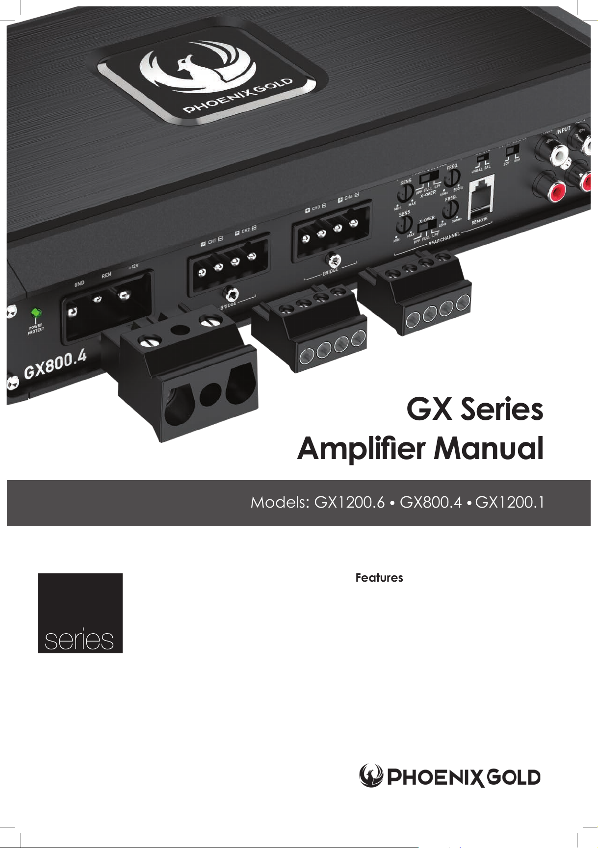
Models: GX1200.6 ● GX800.4 ● GX1200.1
GX
New for 2021 is Phoenix Gold’s GX line of ampliers.
Designed to cover a multitude of installation needs,
GX is packed with the features and power you can
expect from the Phoenix Gold brand. Included in the
line are our proprietary PG quick connects for high
current capability and reliability while delivering uber
clean and quick installations. The chassis has been
optimized by utilizing BFD (Balanced Flow Dissipation)
to keep the amplier running cool when the music is hot.
GX Series
Amplier Manual
Features
• Class D Topology
• Selectable Balanced / Unbalanced Inputs
• Surface-Mount Component Technology
• Multi-Input Selector
• Low Pass and Subsonic Crossovers (GX1200.1)
• Proprietary PG Quick Connects
• Flush Mountable Bass Knob
• Full Radiation Heat Sink
• Single-sided Control Panel
• Onboard Short/Therm/Imped Protection
• 0-180° Variable Phase Shift (GX1200.1)
Page 2

A Power Brand of AAMP Global.
15500 Lightwave Drive, Suite 202
Clearwater, Florida 33760
P: 866-788-4237
[email protected]
www.phoenixgold.com
Phoenix Gold Product Warranty
LIMITED WARRANTY ON AMPLIFIERS
Phoenix Gold warrants this product to be free of defects in materials and workmanship for a period of one (1) years
from the original date of purchase. This warranty is not transferable and applies only to the original purchaser from an
authorized Phoenix Gold dealer in the United States of America only. Should service be necessary under this warranty
for any reason due to manufacturing defect or malfunction, Phoenix Gold will (at its discretion), repair or replace the
defective product with new or remanufactured product at no charge. Damage caused by the following is not covered
under warranty: accident, misuse, abuse, product modication or neglect, failure to follow installation instructions,
unauthorized repair attempts, misrepresentations by the seller. This warranty does not cover incidental or consequential
damages and does not cover the cost of removing or reinstalling the unit(s). Cosmetic damage due to accident or
normal wear and tear is not covered under warranty. Additional warranty coverages are available, see your warranty
card for specic options based on your geographic region and product.
INTERNATIONAL WARRANTIES:
Products purchased outside the United States of America are covered only by that country’s Authorized Phoenix Gold
reseller and not by Phoenix Gold. Consumers needing service or warranty information for these products must contact
that country’s reseller for information.
© 2020 Phoenix Gold • www.phoenixgold.com
Designed and Engineered in the USA
Expertly Manufactured in China
Page 3
© 2020 Phoenix Gold • www.phoenixgold.com
Amplifier Owner’s Manual
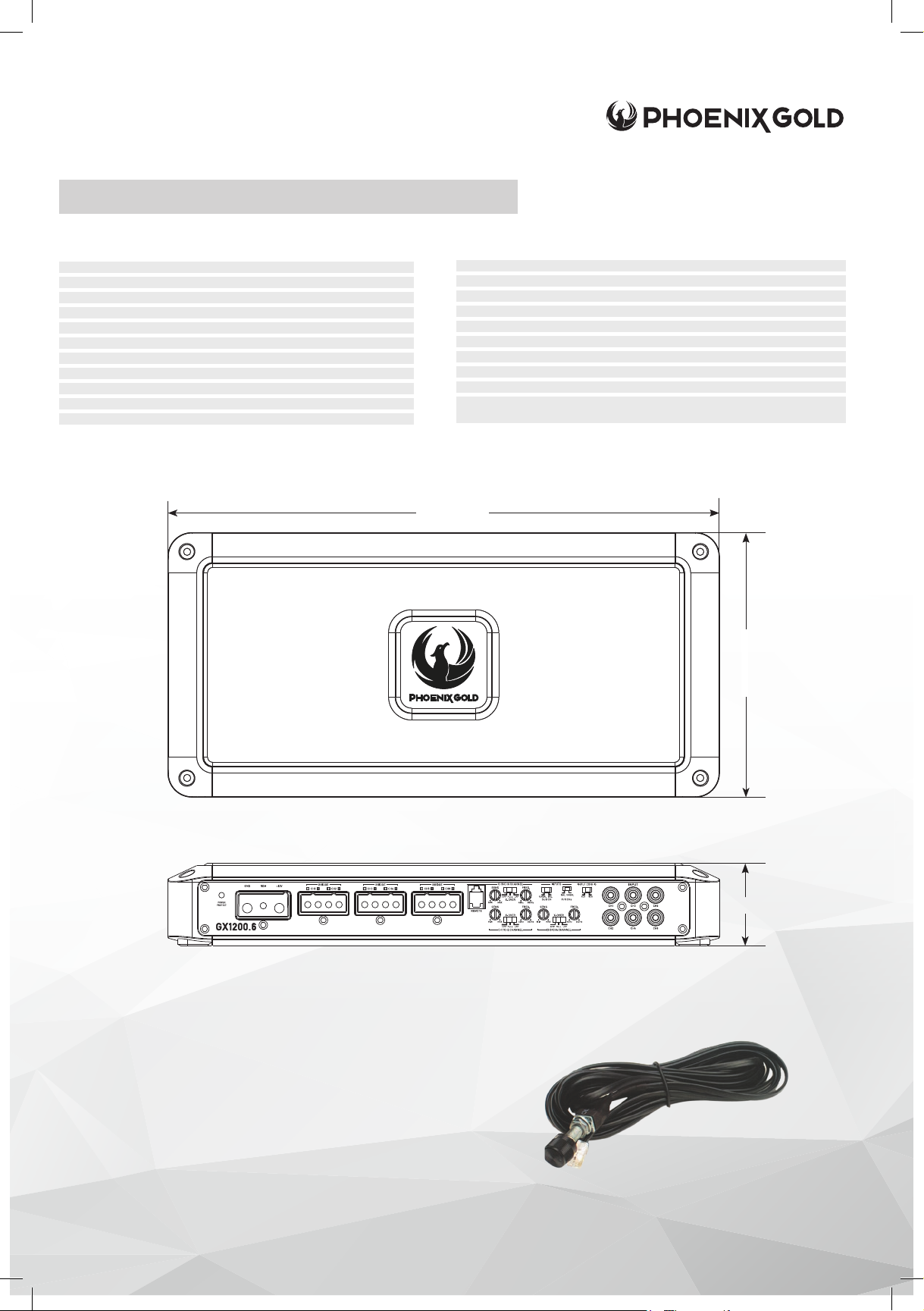
GX 1200.6 SPECIFICATIONS
RMS Power Ratings listed at less than 1% THD @ 14.4v
Number of Channels: 6
4Ω: CH 1-6 125W x 6
2Ω: CH 1-6 200W x 6
4Ω Bridged: 400W x 3
Total RMS Power (Sum of rated power):
Bridgeable: Yes
Crossover Control, Linkwitz-Riley: FULL/HP/LP
Input Selection: 0.4-10V
Signal to Noise (@ CEA Standard): >100dB
Frequency Response: Full Range 10-40k
1200W
40Hz - 500Hz @ 12dB/Oct
GX1200.6 SPECIFICATIONS
Topology Class D
Heatsink Type: Extruded Aluminum
Cooling Type: Radiation
Operating Voltage: 8V to 16V
Switchable Auto-Turn On: No
Power Supply Type: Unregulated
Power Terminal: 4 Gauge Quick Connect
Speaker Terminal: 8 Gauge Quick Connect
Recommended Fusing: 80A
Dimensions (L x W x H): 13.54” x 6.5” x 2.03”
344mm x 165mm x 51.5mm
13.54in / 344mm
Remote Bass Controller:
Flush mount level controller. Fine tune your bass output with a simple
turn of the precision controller. 16ft of cable included.
6.5in / 165mm
2.03in / 51.5mm
IMPORTANT: A power birth certicate is included for each amplier. GX ampliers are
conservatively rated and will exceed their RMS power rating shown here.
All RMS power ratings and measurements are at 14.4 volts with no more than 1% THD.
Page 4
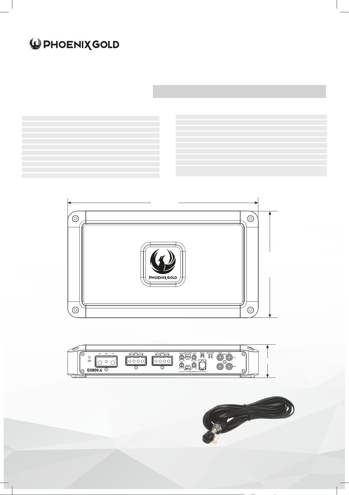
GX800.4 SPECIFICATIONS
GX800.4 SPECIFICATIONS
RMS Power Ratings listed at less than 1% THD @ 14.4v
Number of Channels: 4
4Ω: CH 1-4 125W x 4
2Ω: CH 1-4 200w x 4
4Ω: Bridged 400w x 2
Total RMS Power
Bridgeable: Yes
Crossover Control, Linkwitz-Riley: FULL/HP/LP
40Hz - 500Hz @ 12dB/Oct
Input Selection: 0.4-10V
Signal to Noise (@ CEA Standard): >100dB
Frequency Response: Full Range 10-40k
(Sum of rated power):
800W
11.57in / 294mm
Amplifier Owner’s Manual
Topology Class D
Heatsink Type: Extruded Aluminum
Cooling Type: Radiation
Operating Voltage: 8V to 16V
Switchable Auto-Turn On: No
Power Supply Type: Unregulated
Power Terminal: 4 Gauge Quick Connect
Speaker Terminal: 8 Gauge Quick Connect
Recommended Fusing: 60A
Dimensions (L x W x H): 11.57” x 6.5” x 2.03”
294mm x 165mm x 51.5mm
Remote Bass Controller:
Flush mount level controller. Fine tune your bass output with a simple
turn of the precision controller. 16ft of cable included.
6.5in / 165mm
2.03in / 51.5mm
© 2020 Phoenix Gold • www.phoenixgold.com
IMPORTANT: A power birth certicate is included for each amplier. GX ampliers are
conservatively rated and will exceed their RMS power rating shown here.
All RMS power ratings and measurements are at 14.4 volts with no more than 1% THD.
Page 5
Amplifier Owner’s Manual
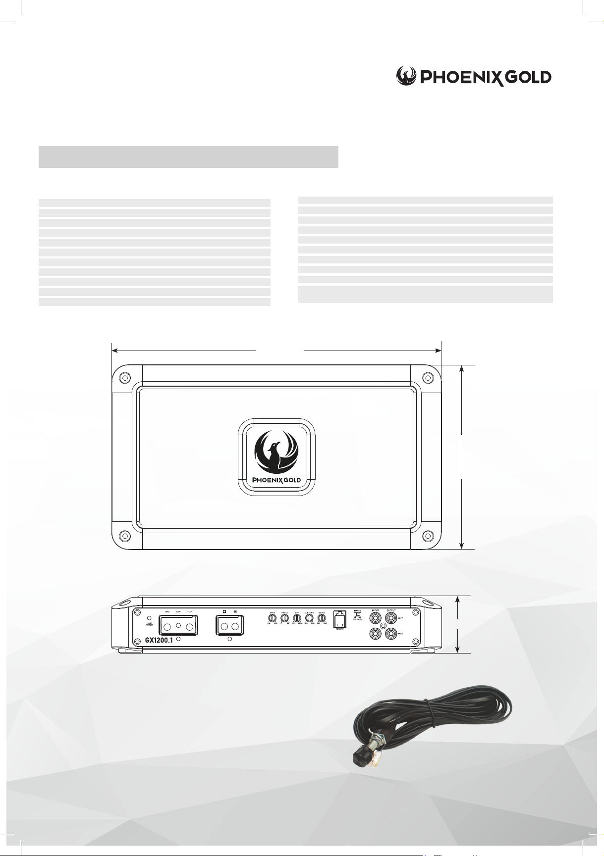
GX1200.1 SPECIFICATIONS
RMS Power Ratings listed at less than 1% THD @ 14.4v
Number of Channels: 1
1Ω: CH 1 1200W x 1
2Ω: CH 1 800W x 1
4Ω: CH 1 500W x 1
Total RMS Power
Bridgeable: N/A
Crossover Control, Linkwitz-Riley: LP
50Hz - 250Hz @ 24dB/Oct
Input Selection: 0.4-10V
Signal to Noise (@ CEA Standard): >100dB
Frequency Response: Sub 15-250Hz
(Sum of rated power):
1200W
11.57in / 294mm
GX1200.1 SPECIFICATIONS
Topology Class D
Heatsink Type: Extruded Aluminum
Cooling Type: Radiation
Operating Voltage: 8V to 16V
Switchable Auto-Turn On: No
Power Supply Type: Unregulated
Power Terminal: 4 Gauge Quick Connect
Speaker Terminal: 8-12 Gauge Quick Connect
Recommended Fusing: 80A
Dimensions (L x W x H): 11.57” x 6.5” x 2.03”
294mm x 165mm x 51.5mm
Remote Bass Controller:
Flush mount level controller. Fine tune your bass output with a simple
turn of the precision controller. 16ft of cable included.
6.5in / 165mm
2.03in / 51.5mm
IMPORTANT: A power birth certicate is included for each amplier. GX ampliers are
conservatively rated and will exceed their RMS power rating shown here.
All RMS power ratings and measurements are at 14.4 volts with no more than 1% THD.
© 2020 Phoenix Gold • www.phoenixgold.com
Page 6
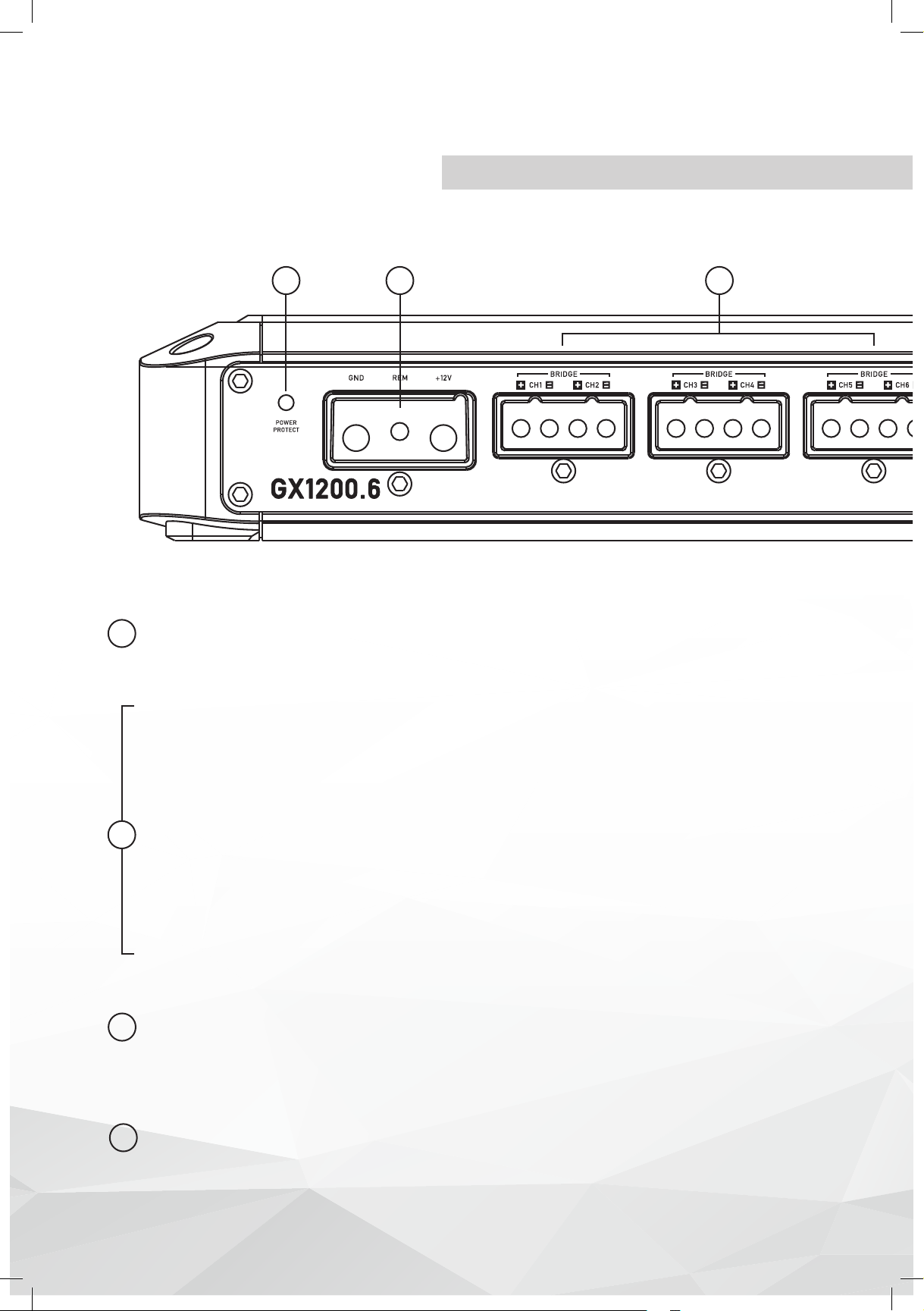
GX1200.6
Multi-Channel Power Amplier
1
POWER/PROTECT LED
Amplier status indicator. Blue indicates all systems working and amplier is on. Red
1
indicates protection mode, from Thermal or Short Circuit. (See Troubleshooting)
GROUND (GND)
This must be connected to the negative terminal of the car’s battery or bolted to a
clean, unpainted part of the chassis of the vehicle. Bad grounds account for 90% of
amplier issues, make sure the amplier is grounded correctly and securely.
2 3
REMOTE (REM)
Connect to switched +12V, usually a trigger wire coming from the head unit or an
2
ignition lead if one is not available.
+12V
This must be connected to the fused positive terminal (+12V) of the car’s battery. A fuse
must be located within 18 inches of the battery to protect the vehicle and should be
fused at, or above, the ampliers fuse rating.
SPEAKER OUTPUTS CH1-6
Used to connect the amplier to speakers. The GX1200.6 minimum impedance is 2
3
Ohms Stereo or 4 Ohms Bridged for all channels.
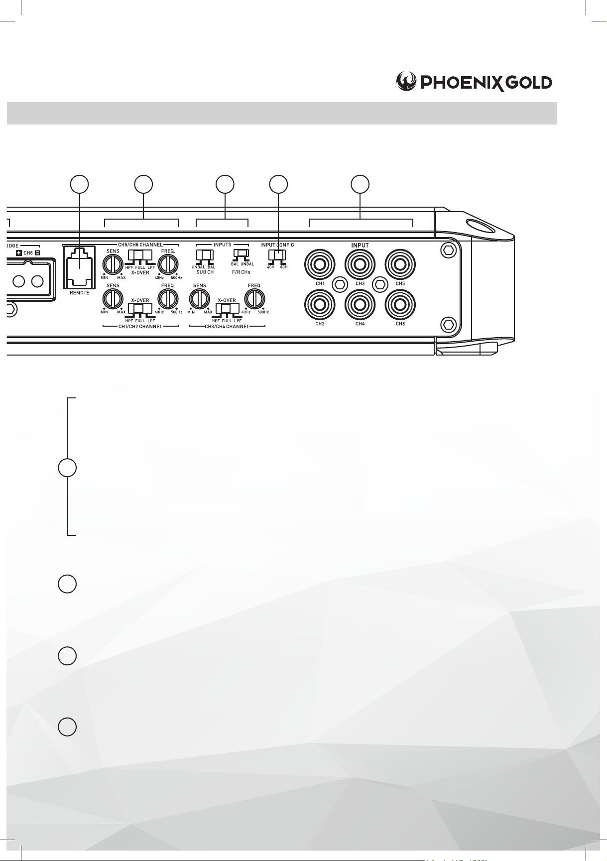
REMOTE LEVEL CONTROL
This port is for connecting the remote level control knob. This allows up to 20dB of
4
volume adjustment. This is not a bass boost, it controls the level of the signal.
The remote only controls CH 5/6.
© 2020 Phoenix Gold • www.phoenixgold.com
Page 7
4 5 6
INPUT GAIN (SENS) CH 1/2, 3/4, 5/6
Used to adjust the input sensitivity to match the input level signal on the channels.
Continuously variable from 0.4V to 10V. Adjust this with the help of a DMM and a test
signal or an Oscilloscope. See System Tuning section for basic setup instructions.
CROSSOVER (X-OVER) CH 1/2, 3/4, 5/6
5
High Pass Filter (HPF): When set, activates a highpass crossover for the channels.
Continuously variable from 40Hz to 500Hz using the FREQ dial.
Full Range (FULL): Select FULL to amplify a full range signal.
Low Pass Filter (LPF): When set, activates a low pass crossover for the channels.
Continuously variable from 40Hz to 500Hz using the FREQ dial.
7
8
INPUTS (F/R CHs, SUB CH)
If you are using RCA or high level signal from an aftermarket head unit, select UNBAL. If
6
you are using high level from a OEM factory source unit or factory amplier select BAL.
INPUT CONFIG (4CH / 6CH)
Input signal selectable for 4 or 6 channels. If only 4 channels of input signal are
7
available, select 4CH to allow signal to split to CH 5+6. Select 6CH if 6 channels
of input are being used.
INPUT (CH1-6)
Connect preamp signal cables (RCA) from the source unit to these terminals.
8
Use of 4 or 6 channels of input signal selectable with INPUT CONFIG switch.
© 2020 Phoenix Gold • www.phoenixgold.com
Page 8
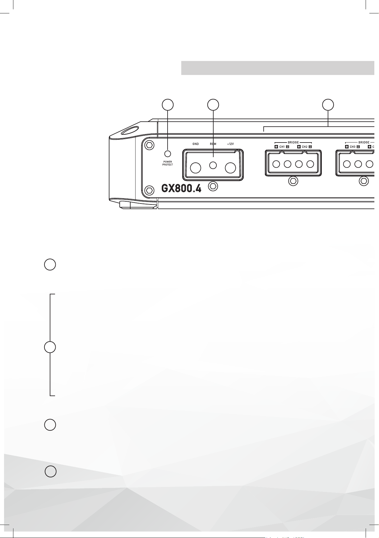
GX800.4
Multi-Channel Power Amplier
1
POWER/PROTECT LED
Amplier status indicator. Blue indicates all systems working and amplier is on. Red
1
indicates protection mode, from Thermal or Short Circuit. (See Troubleshooting)
2 3
GROUND (GND)
This must be connected to the negative terminal of the car’s battery or bolted to a
clean, unpainted part of the chassis of the vehicle. Bad grounds account for 90% of
amplier issues, make sure the amplier is grounded correctly and securely.
REMOTE (REM)
Connect to switched +12V, usually a trigger wire coming from the head unit or an
2
ignition lead if one is not available.
+12V
This must be connected to the fused positive terminal (+12V) of the car’s battery. A fuse
must be located within 18 inches of the battery to protect the vehicle and should be
fused at, or above, the ampliers fuse rating.
SPEAKER OUTPUTS CH1-4
Used to connect the amplier to speakers. The GX800.4 minimum impedance is 2 Ohms
3
Stereo or 4 Ohms Bridged for all channels.
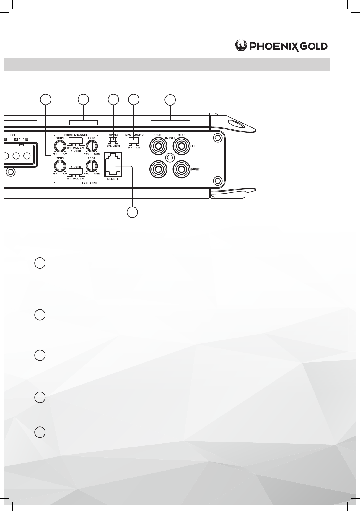
INPUT GAIN (SENS) Front Channel, Rear Channel
Used to adjust the input sensitivity to match the input level signal on the channels.
4
Continuously variable from 0.4V to 10V. Adjust this with the help of a DMM and a test
signal or an Oscilloscope. See System Tuning section for basic setup instructions.
© 2020 Phoenix Gold • www.phoenixgold.com
Page 9
4 5 6
7
8
9
CROSSOVER (X-OVER) Front Channel, Rear Channel
High Pass Filter (HPF): When set, activates a highpass crossover for the channels.
Continuously variable from 40Hz to 500Hz using the FREQ dial.
5
Full Range (FULL): Select FULL to amplify a full range signal.
Low Pass Filter (LPF): When set, activates a low pass crossover for the channels.
Continuously variable from 40Hz to 500Hz using the FREQ dial.
INPUTS
If you are using RCA or high level signal from an aftermarket head unit, select UNBAL. If
6
you are using high level from a OEM factory source unit or factory amplier select BAL.
INPUT CONFIG (2CH / 4CH)
Input signal selectable for 2 or 4 channels. If only 2 channels of input signal are
7
available, select 2CH to allow signal to split to REAR Channels. Select 4CH if 4
channels of input are used.
INPUT (Front / Rear)
Connect preamp signal cables (RCA) from the source unit to these terminals.
8
Use of 2 or 4 channels of input signal selectable with INPUT CONFIG switch.
REMOTE LEVEL CONTROL
This port is for connecting the remote level control knob. This allows up to 20dB of
9
volume adjustment. This is not a bass boost, it controls the level of the signal.
The remote only controls REAR Channel level.
© 2020 Phoenix Gold • www.phoenixgold.com
Page 10
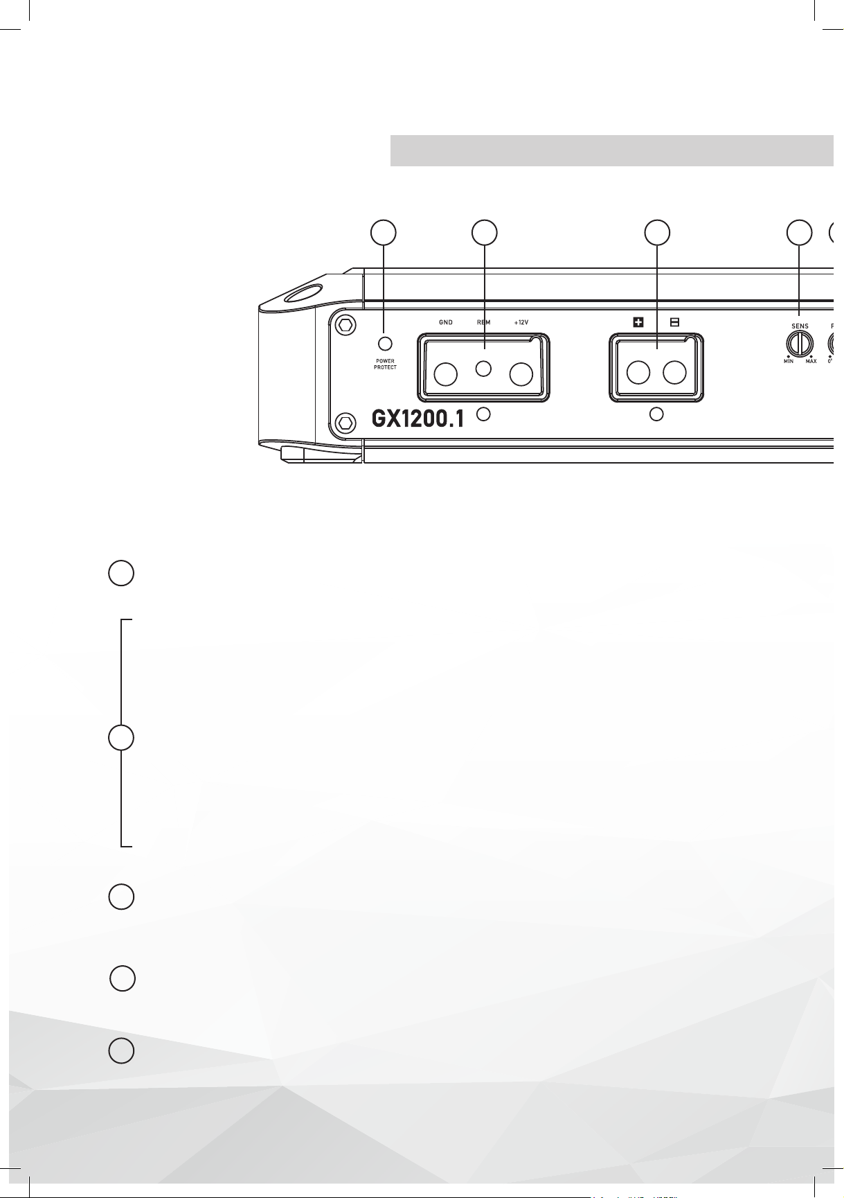
GX1200.1
Monoblock Power Amplier
1
POWER/PROTECT LED
Amplier status indicator. Blue indicates all systems working and amplier is on. Red
1
indicates protection mode, from Thermal or Short Circuit. (See Troubleshooting)
GROUND (GND)
This must be connected to the negative terminal of the car’s battery or bolted to a
clean, unpainted part of the chassis of the vehicle. Bad grounds account for 90% of
amplier issues, make sure the amplier is grounded correctly and securely.
2 3 4
REMOTE (REM)
Connect to switched +12V, usually a trigger wire coming from the head unit or an
2
ignition lead if one is not available.
+12V
This must be connected to the fused positive terminal (+12V) of the car’s battery. A fuse
must be located within 18 inches of the battery to protect the vehicle and should be
fused at, or above, the ampliers fuse rating.
SPEAKER OUTPUT
Used to connect the amplier to speakers. The GX1200.0 minimum impedance is 1
3
Ohms
INPUT GAIN (SENS)
Used to adjust the input sensitivity to match the input level signal. Continuously
4
variable from 0.4V to 10V. Adjust this with the help of a DMM and a test signal or an
Oscilloscope. See System Tuning section for basic setup instructions.
PHASE
Controls the Phase from 0-180°. Properly adjusting phase will allow enhanced bass
5
response, dynamics and impact at any volume.
© 2020 Phoenix Gold • www.phoenixgold.com
Page 11
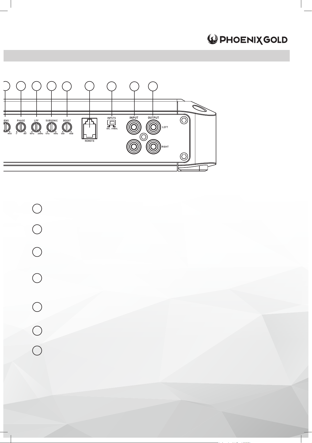
4
5 6
7 9
LOW PASS FILTER (LPF)
6
7
Sets low pass crossover frequency. Continuously variable from 50Hz to 250Hz
SUBSONIC
Continuously variable lter from 10Hz-55Hz to remove low inaudible frequencies to
increase system efciency and protect speakers.
8
10 11 12
8
9
10
11
12
BOOST
Controls the bass boost from 0 to +18dB
REMOTE LEVEL CONTROL
This port is for connecting the remote subwoofer level control knob. This allows up to
20dB of volume adjustment. This is not a bass boost, it controls the level of the low pass
signal.
INPUTS
If you are using RCA or high level signal from an aftermarket head unit, select UNBAL. If
you are using high level from a OEM factory source unit or factory amplier select BAL.
INPUT
Connect preamp signal cables (RCA) from the source unit to these terminals.
OUTPUT
Used to connect to a secondary amplier without degrading signal strength.
© 2020 Phoenix Gold • www.phoenixgold.com
Page 12

Amplifier Owner’s Manual
© 2020 Phoenix Gold • www.phoenixgold.com
SYSTEM TUNING
1. Install all system fuses.
2. Set the amplier’s input sensitivity controls to their minimum
positions (full counterclockwise).
3. Set all amplier crossover switches according to your system’s
design.
4. Make preliminary adjustments to the crossover frequency, usually
80Hz is a good starting point for high and low pass. It may be
necessary to ne tune the crossover frequency later for the best
overall sound quality.
5. If using a Remote Subwoofer Level Control, set it to maximum (full
clockwise).
6. Turn the headunit on with the volume set to minimum.
7. Visually check the amplier has turned on via the power LED.
8. Check the condition of all other components to make sure they
are powered up.
9. Set the headunit’s tone controls, balance, and fader to the
center (at) position. Turn off any loudness or other signal
processing features.
10. Set the volume control of the headunit to 3/4 of maximum
volume. Play music you typically listen to through the system.
11. Turn up the sensitivity or input level control on the amplier until
the speakers reach maximum undistorted output.
12. Repeat sensitivity level adjustments for all other ampliers.
13. Reduce the headunit’s volume to a comfortable level.
14. Listen to various musical selections to check overall system
balance. Compare front to rear, midbass to midrange, etc. If one
speaker set is too loud compared to another, then its level must
be lowered to blend correctly with the other speakers.
Note: For subwoofers controlled by the Remote level control,
keep the level setting from step 11 or 12. Use the control to blend
subwoofers with the rest of the system. The correct subwoofer
volume will change depending on road noise and differences in
recordings.
15. Fine tune crossover frequencies to achieve the smoothest
possible blending of each speaker set.
16. Adjust the Bass Equalization Controls on the amplier, headunit or
processor upstream if necessary to increase output.
Note: Use these controls sparingly. Every 3dB of boost requires
double the power at 45Hz. If your subwoofer system requires a lot
of boost to sound good, there may be a problem. Look for out-ofphase woofers, a leaking subwoofer box, or incorrect box size.
17. With all levels set correctly, the system will reach overall maximum
undistorted output at the volume level set in step 10.
TROUBLESHOOTING
NO POWER:
Check voltage at the amplier with a DMM (volt meter), +12v and R
(with head unit on) the voltage should register between 11.5V and
14.4V when using the attached ground lead of the amplier. Check
that the amplier’s ground is good and has a solid connection. Check
fuse at the battery. Use a meter to verify connection from one end of
the fuse to the other, breaks may not always be visible. If the fuse is
blown, check the power wire and also the amplier for a short. If the
short is in the amplier itself, see your Phoenix Gold dealer. If no short is
present, replace the fuse.
POWER WITHOUT SOUND:
Turn the amplier off and check all input and output signal cables and
power connections. Check the speakers for shorts with a DMM (volt
meter) or by connecting them to another audio source. After making
sure everything is correct, turn the amplier on again.
POWER, NO SOUND, PROTECT LED LIT:
The red PROTECT LED lights when the amplier shuts down for either
thermal or over-current protection. A high internal amplier operating
temperature will trigger thermal shutdown: after it cools about 5°C, the
amplier will restart. A shorted speaker lead or operation into unusually
low impedance loads will trigger over-current shutdown: cycle power
at the amplier R terminal to restore operation. Check for shorted
speaker wiring or damaged speakers or crossover systems if overcurrent shutdown occurs.
NO SOUND FROM ONE OR MORE CHANNELS:
Check the balance control in the head unit. Check speaker
connections. Check signal input connection. Very low output: Check
your head unit’s fader control or the amplier’s input sensitivity level.
Make sure subsonic frequency control is not set too high and LPF
frequency control is not set too low at the same time.
FREQUENT AMPLIFIER SHUTDOWN WITH AUTOMATIC RECOVERY:
This indicates chronic amplier thermal shutdown because of
operation at consistently high internal temperatures. High operating
temperature can be caused by inadequate ventilation. Make sure
you are not running a lower than recommend impedance. Also check
for damaged speakers or passive crossover systems. Finally, chronic
thermal shutdown may result from otherwise normal operation of the
amplier at elevated output power levels, which can be resolved
by providing additional amplier cooling, installing a higher-power
amplier, or reducing amplier output level.
POWER CYCLES ON/OFF QUICKLY:
If the power indicator if going off repeatedly when the audio system is
on, check all ground connections. Check the amplier’s connection
to the battery. Check battery voltage. If low, recharge or replace the
battery.
REV 081420
 Loading...