

Page 1
AST-220S
AST-220C
USER MANUAL
Part # 8100.0310
Phoenix Gold International, Inc. 9300 North Decatur Street Portland, Oregon 97203 Tel: 503.286.9300 Fax: 503.978.3391
Website: www.audiosource.net Email: support@phoenixgold.com
Page 2
The AudioSource AST 220S and AST 220C were
specifically designed for use in a Home Theater system.
Additionally, this speaker system has been optimized to
enhance the total theater experience with flat panel
displays such as Plasma, LCD and DLP Projection and
Rear Projection displays.
If you wish to extend the speakers beyond the 2” to 3”
minimum that presents no problem. Please note that the
distance between the right and left speakers should not be
greater than the distance from the speakers to the
listener’s position.
The AST 220S is designed to be used as the satellite
speakers; left and right front as well as left and right side
or rear speakers. They are designed to be wall mounted
using the supplied brackets or they can be set up to be
table mounted utilizing the supplied bases. One pair may
be set up to be floor standing using the stands provided.
The AST 220C is the specifically designed for use as the
front center channel speaker and can be mounted to the
wall beneath the display using the mounting bracket
provided or it may be table mounted on any flat surface
using the Isolation Mounting Feet included with the
AST 220C. These feet were custom molded to fit the
bottom edge of the AST 220C and should be placed near
either end in a manner that is aesthetically pleasing to
the user. The molded surface has an adhesive layer that
can be exposed by removing the protective paper layer
once you have determined the placement of the feet for
your intended use.
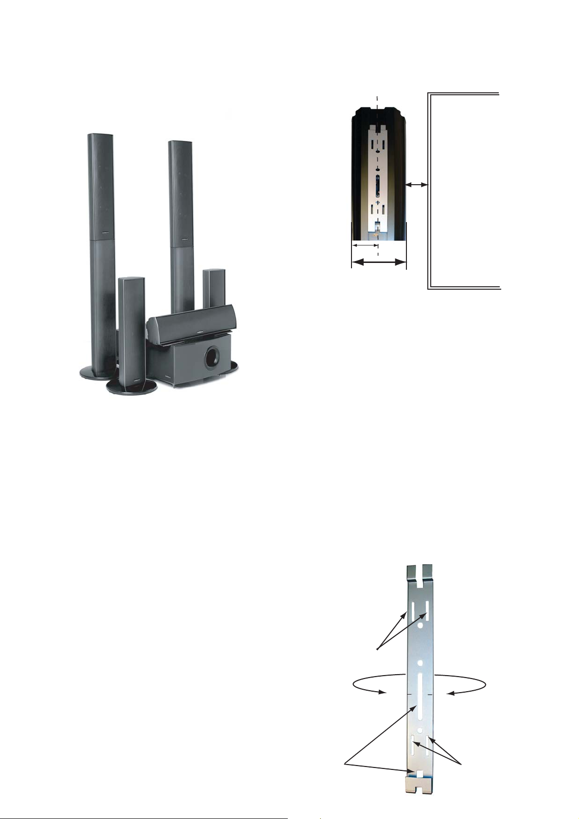
2“
Min.
2.5”
Display
or
Screen
Area
5“ wide
Mounting the Wall Brackets
The wall mounting brackets are designed to be attached to
the wall surface using screws. Where no underlying wall
stud is available for proper placement it is highly recommended that an appropriate wall anchor be used.
We do not recommend a particular type since many
different wall surfaces may be encountered. If you are
unsure as to which type of wall anchor to use consult with
your local Hardware or Do-It-Yourself store specialist to
determine the correct anchor for the type of wall surface in
your home. Note: the weight of an AST 220S or an AST 220C is
7.1 pounds.
The wall mounting bracket has four slots to accept screws
for attaching it to the wall surface. If you are locating the
bracket over a wall stud these slots will fall within the width
of a standard 2x4 or 2x6 wall stud. There is a slot at the
bottom and in the middle of the bracket to allow the
speaker cable to be brought through both the wall and the
bracket to connect to the terminals on the rear of
the AST 220S and the AST 220C loudspeakers.
Placement of the Brackets
The placement of the brackets for the left and right front
loudspeakers should considered from the point of
making the loudspeakers perform correct acoustically
while maintaining an aesthetically pleasing appearance.
The AST 220S has very wide dispersion characteristics
in the horizontal plane. Therefore, the AST 220S
loudspeakers may be mounted in close proximity to your
display or screen area. We recommend that you leave a
minimum of 2 to 3 inches between the edge of the
display or screen area.
Mounting Slots
for Screws
Speaker
Cable
Slots
2
Center Line
Mounting Slots
for Screws
Page 3

The bracket for the AST 220S and AST 220C has a
“Center Line” stamped into it, and indicates where the
center of the speaker will be located when mounted onto
the bracket. Use this “Center Line” to locate the brackets
vertically For the AST 220S loudspeakers and horizontally for the AST 220 C.
By drawing horizontal and vertical center lines through
the area covered by the display you can use the “Center
Line” of the brackets to properly center the speakers on
the display in the horizontal and vertical planes. Use a
level to keep the vertical brackets plumb and the horizontal bracket level.
Note: If the screws do not
seem to align properly with
the four channels of the
aluminum extrusion of the
AST 220S, loosen the four
Pan Head screws that retain
the steel plate to the bottom
of the “Base”. (Do not remove
these screws.) Re-align the
base of the extrusion and
tighten all screws. Be careful
not to overtighten the screws
and possibly strip the channel
to the point the screws will
not grip snugly.
“Center Line”
Display Area
“Center Line”
Assembling the Base to the AST 220S
To attach the “Base” to the AST 220S, use a Phillips head
screwdriver to remove the four screws from the bottom end
cap of the AST 220S speaker.
Assembling the AST-Stands
If you wish to use a pair of the AST 220S speakers as floor
standing speakers, they can be mounted to the
AST-Stands in the following manner.
Mount the supplied bases to the AST-Stands as described
in the section above “Assembling the Base to the
AST 220S”.
Next, remove the four screws from the bottom end cap of
the AST 220S speaker, set the end cap and four screws
aside. Please retain these parts for possible use later.
Next, insert the 1.5” x 9” metal
support into the channel on
the rear or the AST-Stand,
and attach to the AST-Stand
with two of the four supplied
screws.
Place the open end of the speaker into the base. Replace
the four screws into the AST 220S. Start all for screws
before fully tightening.
Screws
Find a pair of wires with slide-on connectors loose in
the bottom of the AST 220S. These will mate with the two
wires extending from the AST-Stands.
3
Page 4

With the AST 220S and the AST-Stand lying flat, attach
the two wires together, noting that the slide-on connectors
are sized differently to maintain proper phase in the
connection. Now, carefully slide the metal support into the
channel on the rear of the AST 220S. Align the four brass
pins extending from the top of the AST-Stand with the four
channels on the inside of the AST 220S, and slide the two
units together so that they fit tightly against the plastic
spacer of the AST-Stand.
Now insert and tighten the two remaining screws
attaching the metal support to the AST 220S.
You may now connect the speaker cable to the terminals
at the bottom of the AST 220S / Stand combination.
Connecting the Speaker cable to the AST 220 speakers
Strip away 1/2 inch of the insulation on the Speaker wire
and tightly twist the strands of each conductor together. If
a soldering iron is available carefuly tin the two conductors of each speaker cable.
Specifications
AST 220S Home Theater Satellite
• Plasma application "slim" wall mount design
loudspeaker system
• Height 20” overall
• Dual 4.25” mid/woofers and poly treated silk dome
tweeter
• Sensitivity: 89 dB/ @ 2.83V / 1m
• Impedance: 8 Ohm nominal
• Frequency Response: +/- 2.5 dB from 90-20 kHz
(-6 dB @ 72 Hz.)
• Recommended safe amplifier power: 15 - 200 watts
RMS
• CAD/CAE designed High order, Asymmetrical,
Phase compensating, acoustical passive crossover
• 3.5” (90
AST 220C Home Theater Center Channel
• Plasma application "slim" wall mount design
loudspeaker system.
• Length 20” overall
• Dual 4.25” mid/woofers and poly treated silk dome
tweeter
• Sensitivity: 89 dB/ @ 2.83V / 1m
• Impedance: 8 Ohm nominal
• Frequency Response: +/- 2.5 dB from 90-20 kHz
(-6 dB @ 72 Hz.)
• Recommended safe amplifier power: 15 - 200 watts
RMS
• CAD/CAE designed High order, Asymmetrical,
Phase compensating, acoustical passive crossover
• 3.5” (90mm) D x 5.25” (133mm) W x 20.25” (514mm)H
mm) D x 5.25” (133mm) W x 20.25” (514mm)H
Next, bend the exposed portion
of the speaker cable to a 90º
angle to the insulation.
Press down the top of the
terminal and insert the
speaker cable into the hole
at the bottom of the connector
in the direction of the closest
end of the connector cup.
Always be careful to observe
proper polarity, making sure to connect (+) to (+) and
connect (-) to (-). Failure to do so will cause a loss of low
frequency response and improper imaging.
AST Stand Home Theater Floor Stand
• Home Theater application "Floor Stand” for AST 220S
• Height 47” overall
• Matching Aluminum Extrusion
• Floor Level Speaker Level Input
• 3.5” D x 5.25” W x 27” H
4
 Loading...