

Page 1
AUTOMATION
User manual
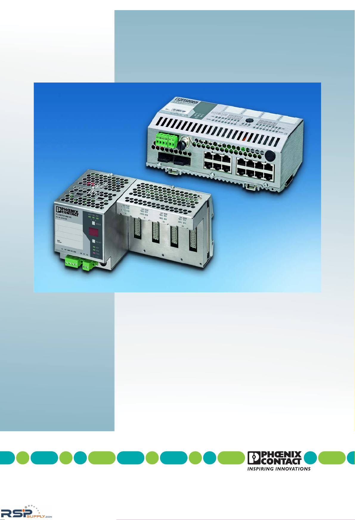
Modular Managed (Compact) Switch System
FL SWITCH MM HS UM E for
FL SWITCH MM HS
FL SWITCH MCS ...
RSPSupply - 1-888-532-2706 - www.RSPSupply.com
http://www.RSPSupply.com/p-14178-Phoenix-Contact-2832357-FL-IF-2TX-VS-RJ-D-Media-Module-for-Modular-Switch.aspx
Page 2

2012-01-23
AUTOMATION
6874_en_15 PHOENIX CONTACT
Description of the hardware and software functions of the
Modular Managed Switch System (MMS) with firmware Version 4.70a and the
Managed Compact Switch (MCS) with firmware Version 4.72
FL SWITCH MM HS UM E
15
—
The MMS and the MCS with firmware Version 4.70a (MMS)/4.72 (MCS) in the Factory Line product range.
The Modular Managed Switch System includes:
- The FL SWITCH MM HS and FL SWITCH MM HS/M head stations
- The FL MXT and FL MXT/M extension modules
- The various FL IF ... interface modules
The Managed Compact Switch includes:
- The FL SWITCH MCS 16TX and FL SWITCH MCS 14TX/2FX MCS switches
- The FL MEM PLUG/FL MEM PLUG/MRM configuration memories
User manual
Designation:
Revision:
Order No.:
This user manual is valid for (see ordering date in chapter 12):
RSPSupply - 1-888-532-2706 - www.RSPSupply.com
http://www.RSPSupply.com/p-14178-Phoenix-Contact-2832357-FL-IF-2TX-VS-RJ-D-Media-Module-for-Modular-Switch.aspx
Page 3
PHOENIX CONTACT
Please observe the following notes
User group of this manual
The use of products described in this manual is oriented exclusively to:
– Qualified electricians or persons instructed by them, who are familiar with applicable
standards and other regulations regarding electrical engineering and, in particular, the
relevant safety concepts.
– Qualified application programmers and software engineers, who are familiar with the
safety concepts of automation technology and applicable standards.
Explanation of symbols used and signal words
How to contact us
Internet Up-to-date information on Phoenix Contact products and our Terms and Conditions can be
found on the Internet at:
www.phoenixcontact.com
Make sure you always use the latest documentation.
It can be downloaded at:
www.phoenixcontact.net/catalog
Subsidiaries If there are any problems that cannot be solved using the documentation, please contact
your Phoenix Contact subsidiary.
Subsidiary contact information is available at www.phoenixcontact.com.
Published by PHOENIX CONTACT GmbH & Co. KG
Flachsmarktstraße 8
32825 Blomberg, GERMANY
Should you have any suggestions or recommendations for improvement of the contents and
layout of our manuals, please send your comments to:
This is the safety alert symbol. It is used to alert you to potential personal injury
hazards. Obey all safety measures that follow this symbol to avoid possible injury or death.
There are three different categories of personal injury that are indicated with a
signal word.
DANGER This indicates a hazardous situation which, if not avoided, will re-
sult in death or serious injury.
WARNING This indicates a hazardous situation which, if not avoided, could
result in death or serious injury.
CAUTION This indicates a hazardous situation which, if not avoided, could
result in minor or moderate injury.
This symbol together with the signal word NOTE and the accompanying text
alert the reader to a situation which may cause damage or malfunction to the
device, hardware/software, or surrounding property.
This symbol and the accompanying text provide the reader with additional information or refer to detailed sources of information.
RSPSupply - 1-888-532-2706 - www.RSPSupply.com
http://www.RSPSupply.com/p-14178-Phoenix-Contact-2832357-FL-IF-2TX-VS-RJ-D-Media-Module-for-Modular-Switch.aspx
Page 4

Please observe the following notes
PHOENIX CONTACT
General terms and conditions of use for technical documentation
Phoenix Contact reserves the right to alter, correct, and/or improve the technical documentation and the products described in the technical documentation at its own discretion and without giving prior notice, insofar as this is reasonable for the user. The same applies to any technical changes that serve the purpose of technical progress.
The receipt of technical documentation (in particular user documentation) does not constitute any further duty on the
part of Phoenix Contact to furnish information on modifications to products and/or technical documentation. You are
responsible to verify the suitability and intended use of the products in your specific application, in particular with regard to observing the applicable standards and regulations. All information made available in the technical data is supplied without any accompanying guarantee, whether expressly mentioned, implied or tacitly assumed.
In general, the provisions of the current standard Terms and Conditions of Phoenix Contact apply exclusively, in particular as concerns any warranty liability.
This manual, including all illustrations contained herein, is copyright protected. Any changes to the contents or the
publication of extracts of this document is prohibited.
Phoenix Contact reserves the right to register its own intellectual property rights for the product identifications of
Phoenix Contact products that are used here. Registration of such intellectual property rights by third parties is prohibited.
Other product identifications may be afforded legal protection, even where they may not be indicated as such.
RSPSupply - 1-888-532-2706 - www.RSPSupply.com
http://www.RSPSupply.com/p-14178-Phoenix-Contact-2832357-FL-IF-2TX-VS-RJ-D-Media-Module-for-Modular-Switch.aspx
Page 5

Table of contents
6874_en_16 PHOENIX CONTACT i
Table of contents
1 The Modular Managed Switch System (MMS) and the Managed Compact Switch (MCS) .....1-1
1.1 Properties (MMS) ...............................................................................................1-1
1.2 Future-proof networks for the highest possible requirements .............................1-1
1.2.1 System components (MMS) ...............................................................1-3
1.2.2 MMS firmware versions and their functions ........................................1-5
1.2.3 Firmware functions and the required hardware (MMS) .......................1-7
1.2.4 Device view (MMS) .............................................................................1-7
1.2.5 Dimensions of the Modular Managed Switch System
for normal operation ..........................................................................1-10
1.2.6 Dimensions of the Modular Managed Switch System
for GL-certified operation ..................................................................1-11
1.2.7 Assignment of ports to slots ..............................................................1-11
1.3 Status and diagnostic indicators.......................................................................1-12
1.3.1 LEDs on the switch and the MMS extension module ........................1-12
1.3.2 Meaning of the 7-segment display (MMS) ........................................1-14
1.4 Properties (MCS)..............................................................................................1-18
1.4.1 Firmware versions and their functions (MCS) ...................................1-18
1.4.2 Firmware functions and the required hardware (MCS) ......................1-21
1.4.3 Dimensions of the MCS ....................................................................1-21
1.4.4 Device view (MCS) ...........................................................................1-22
2 Mounting and installation ........................................................................................................2-1
2.1 Mounting and removing the MMS head station or MCS .....................................2-1
2.2 Mounting and removing extension modules (MMS) ...........................................2-3
2.3 Mounting and removing interface modules (MMS) .............................................2-5
2.4 Arrangement of the interface modules................................................................2-7
2.5 Mounting and removing the FL M LABEL labeling field (accessories) ................2-8
2.5.1 Mounting .............................................................................................2-8
2.5.2 Removal ..............................................................................................2-9
2.5.3 Dimensions of the labeling field ..........................................................2-9
2.6 FL MEM PLUG (accessories).............................................................................2-9
2.7 Installing the MMS or MCS ...............................................................................2-10
2.7.1 Connecting the supply voltage to the MMS/MCS ..............................2-10
2.7.2 Connecting the supply voltage to the
FL SWITCH MM HS/M for GL-certified operation .............................2-11
2.7.3 Alarm contact ....................................................................................2-12
2.7.4 V.24 (RS-232) interface for external management ............................ 2-13
2.8 Grounding.........................................................................................................2-13
3 Startup and functions ..............................................................................................................3-1
3.1 Basic settings .....................................................................................................3-1
RSPSupply - 1-888-532-2706 - www.RSPSupply.com
http://www.RSPSupply.com/p-14178-Phoenix-Contact-2832357-FL-IF-2TX-VS-RJ-D-Media-Module-for-Modular-Switch.aspx
Page 6

FL SWITCH MM HS / FL SWITCH MCS
ii
PHOENIX CONTACT 6874_en_16
3.1.1 Default upon delivery/default settings .................................................3-1
3.2 Using Smart mode..............................................................................................3-2
3.2.1 Activating Smart mode ........................................................................3-2
3.2.2 Assigning IP parameters .....................................................................3-4
3.2.3 Flowchart after a restart ......................................................................3-8
3.3 Starting up interface modules with the MMS ....................................................3-10
3.3.1 FL IF 2TX VS-RJ ... ...........................................................................3-10
3.3.2 FL IF 2POF 10/100 ... ........................................................................3-12
3.3.3 FL IF 2HCS 100 ... ............................................................................3-15
3.3.4 FL IF 2FX SC .../FL IF 2FX SM SC ... ..............................................3-17
3.3.5 FL IF 2FX ST-D .................................................................................3-19
3.3.6 FL IF TX/POF 10/100 ... ....................................................................3-20
3.3.7 FL IF TX/HCS 100 ... .........................................................................3-21
3.3.8 FL IF MEM 2TX-D/FL IF MEM 2TX-D/MRM ......................................3-23
3.3.9 FL IF 2PSE-F ....................................................................................3-24
3.3.10 FL IF 2POF SCRJ-D ........................................................................3-28
3.4 Frame switching ...............................................................................................3-31
3.4.1 Store-and-forward .............................................................................3-31
3.4.2 Multi-address function .......................................................................3-31
3.4.3 Learning addresses ..........................................................................3-31
3.4.4 Prioritization ......................................................................................3-32
4 Configuration and diagnostics .................................................................................................4-1
4.1 Factory Manager ................................................................................................4-1
4.1.1 General function ..................................................................................4-1
4.1.2 Assigning IP parameters .....................................................................4-1
4.1.3 Configuration and diagnostics .............................................................4-3
4.2 Web-based management (WBM).....................................................................4-10
4.2.1 General function ................................................................................4-10
4.2.2 Requirements for the use of WBM ....................................................4-11
4.2.3 Functions/information in WBM ..........................................................4-12
4.3 Simple Network Management Protocol (SNMP)...............................................4-44
4.3.1 General function ................................................................................4-44
4.3.2 Diagram of SNMP management .......................................................4-47
4.3.3 RFC1213 MIB - MIB II .......................................................................4-49
4.3.4 RMON MIB (1.3.6.1.2.1.16) ..............................................................4-56
4.3.5 Bridge MIB (1.3.6.1.2.1.17) ...............................................................4-62
4.3.6 pBridgeMIB (1.3.6.1.2.1.17.6) ...........................................................4-64
4.3.7 qBridgeMIB (1.3.6.1.2.1.17.7) ...........................................................4-65
4.3.8 rstp MIB (1.3.6.1.2.1.17.11) ..............................................................4-68
4.3.9 IANAifType MIB (1.3.6.1.2.1.30) .......................................................4-69
4.3.10 IF MIB (1.3.6.1.2.1.31) ......................................................................4-69
4.3.11 pnoRedundancy MIB 1.3.6.1.4.1.24686 ........................................... 4-72
4.3.12 Private MIBs ......................................................................................4-73
RSPSupply - 1-888-532-2706 - www.RSPSupply.com
http://www.RSPSupply.com/p-14178-Phoenix-Contact-2832357-FL-IF-2TX-VS-RJ-D-Media-Module-for-Modular-Switch.aspx
Page 7

Table of contents
6874_en_16 PHOENIX CONTACT iii
4.4 Management via local V.24 (RS-232) communication interface .....................4-125
4.4.1 General function ..............................................................................4-125
4.4.2 User interface functions ..................................................................4-126
4.4.3 Starting with faulty software (firmware) ...........................................4-129
4.5 Management via Telnet ..................................................................................4-132
4.5.1 Configuring the Telnet terminal .......................................................4-132
4.5.2 Telnet interface functions ................................................................4-132
5 (Rapid) Spanning Tree ............................................................................................................5-1
5.1 General function .................................................................................................5-1
5.2 (R)STP startup....................................................................................................5-2
5.2.1 Enabling (R)STP on all switches involved ...........................................5-2
5.2.2 Connection failure - Example ............................................................5-11
5.2.3 Mixed operation of RSTP and STP ...................................................5-13
5.2.4 Topology detection of a Rapid Spanning Tree network (RSTP) ........5-13
5.2.5 Configuration notes for Rapid Spanning Tree ...................................5-16
6 Media Redundancy Protocol (MRP) .......................................................................................6-1
6.1 General function .................................................................................................6-1
6.2 MRP manager ....................................................................................................6-1
6.2.1 Network examples ..............................................................................6-2
6.3 Enabling web pages for using MRP in WBM ......................................................6-4
6.4 Configuration of MRP .........................................................................................6-4
6.4.1 MRP General ......................................................................................6-4
6.4.2 MRP Configuration ..............................................................................6-5
7 Multicast filtering ....................................................................................................................7-1
7.1 Basics.................................................................................................................7-1
7.2 Enabling the web pages for multicast filtering in WBM .......................................7-1
7.3 Static multicast groups .......................................................................................7-1
7.3.1 "Current Multicast Groups" web page .................................................7-2
7.3.2 Creating static multicast groups ..........................................................7-2
7.3.3 Procedure for creating a multicast group ............................................7-4
7.4 Dynamic multicast groups ..................................................................................7-7
7.4.1 Internet Group Management Protocol (IGMP) .....................................7-7
7.4.2 "General Multicast Configuration" web page .......................................7-8
7.5 Multicast source detection..................................................................................7-9
7.5.1 Properties of multicast source detection .............................................7-9
8 Virtual Local Area Network (VLAN) ........................................................................................8-1
8.1 Basics.................................................................................................................8-1
8.2 Enabling the VLAN web pages in web-based management...............................8-1
RSPSupply - 1-888-532-2706 - www.RSPSupply.com
http://www.RSPSupply.com/p-14178-Phoenix-Contact-2832357-FL-IF-2TX-VS-RJ-D-Media-Module-for-Modular-Switch.aspx
Page 8

FL SWITCH MM HS / FL SWITCH MCS
iv
PHOENIX CONTACT 6874_en_16
8.2.1 Management VLAN ID ........................................................................8-2
8.2.2 Changing the management VLAN ID ..................................................8-2
8.3 General VLAN configuration...............................................................................8-3
8.4 Current VLANs ...................................................................................................8-4
8.4.1 Static VLANs .......................................................................................8-5
8.4.2 VLAN Port Configuration .....................................................................8-6
8.4.3 VLAN Port Configuration Table ...........................................................8-6
8.5 Creating static VLANs ........................................................................................8-7
8.5.1 Dynamic configuration ........................................................................8-9
8.6 VLAN and (R)STP ..............................................................................................8-9
9 Operating as a PROFINET device ..........................................................................................9-1
9.1 Preparing the switch for PROFINET mode .........................................................9-1
9.2 Switch as a PROFINET IO device ......................................................................9-2
9.2.1 Configuration in the engineering tool ...................................................9-2
9.2.2 Configuring the switch as a PROFINET IO device ..............................9-4
9.2.3 Configuration via the engineering tool .................................................9-5
9.2.4 PROFINET flashing function ...............................................................9-5
9.2.5 Device naming ....................................................................................9-5
9.2.6 Operating in the PROFINET environment ...........................................9-5
9.3 PROFINET alarms..............................................................................................9-6
9.3.1 Alarms in WBM ...................................................................................9-7
9.4 Process data communication .............................................................................9-7
9.4.1 Control word .......................................................................................9-8
9.5 PDEV - Function description...............................................................................9-9
9.5.1 PROFINET stack and PDEV function ..................................................9-9
9.6 Conformance according to PROFINET conformance class B ..........................9-10
10 LLDP (Link Layer Discovery Protocol) ..................................................................................10-1
10.1 Basics...............................................................................................................10-1
10.2 Representation of the topology in an engineering tool......................................10-4
11 DHCP relay agent .................................................................................................................11-1
11.1 Activating the DHCP relay agent ......................................................................11-1
12 Technical data and ordering data ..........................................................................................12-1
12.1 Technical data ..................................................................................................12-1
12.1.1 Technical data (MMS) .......................................................................12-1
12.1.2 Technical data (MCS) .......................................................................12-5
12.1.3 Revision history of this manual ..........................................................12-7
12.2 Typical current consumption (MMS) - (Example)..............................................12-8
RSPSupply - 1-888-532-2706 - www.RSPSupply.com
http://www.RSPSupply.com/p-14178-Phoenix-Contact-2832357-FL-IF-2TX-VS-RJ-D-Media-Module-for-Modular-Switch.aspx
Page 9

Table of contents
6874_en_16 PHOENIX CONTACT v
12.3 Ordering data ...................................................................................................12-9
12.3.1 Ordering data (MMS) ........................................................................12-9
12.3.2 Ordering data for GL-certified components
(GL Certificate No. 24 2750 4 HH) ....................................................12-9
12.3.3 Ordering data (MCS) ......................................................................12-10
12.3.4 Accessories (MMS/MCS) ...............................................................12-10
RSPSupply - 1-888-532-2706 - www.RSPSupply.com
http://www.RSPSupply.com/p-14178-Phoenix-Contact-2832357-FL-IF-2TX-VS-RJ-D-Media-Module-for-Modular-Switch.aspx
Page 10

FL SWITCH MM HS / FL SWITCH MCS
vi
PHOENIX CONTACT 6874_en_16
RSPSupply - 1-888-532-2706 - www.RSPSupply.com
http://www.RSPSupply.com/p-14178-Phoenix-Contact-2832357-FL-IF-2TX-VS-RJ-D-Media-Module-for-Modular-Switch.aspx
Page 11
The Modular Managed Switch System (MMS) and the Managed Compact Switch (MCS)
6874_en_16 PHOENIX CONTACT 1-1
1 The Modular Managed Switch System (MMS) and the
Managed Compact Switch (MCS)
1.1 Properties (MMS)
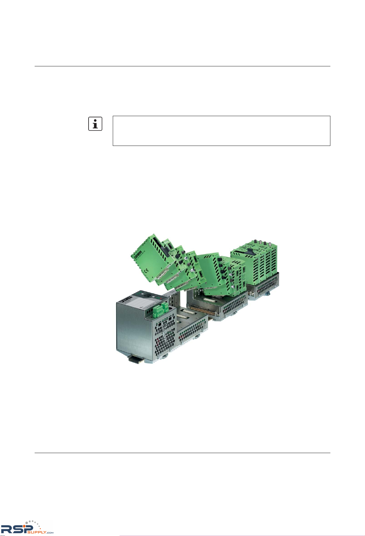
The Modular Managed Switch (Modular Managed Switch System - MMS) is an Ethernet
switch, which is suitable for industrial use and consists of a head station, extension
modules, and interface modules. The head station and extension modules contain the
entire Ethernet switching technology. Interface modules provide the interface to the desired
physical transmission method. An extension module can be used to extend the head station
from eight ports to 16 ports, and the use of two extension modules gives a maximum of
24 ports. The desired transmission medium can be freely selected using the various
interface modules.
Figure 1-1 The Modular Managed Switch System
1.2 Future-proof networks for the highest possible
requirements
Transmission method 10/100 Mbps polymer/HCS fibers on the MMS
Easy to assemble polymer fibers can now also be used for Ethernet. This cost-effective fiber
optic technology can cover distances of up to 50 m. This provides cost savings both during
installation and for maintenance when replacing mechanically damaged fiber optic cables.
HCS fiber technology is available for distances of up to 300 m.
Unless stated otherwise, all information in this manual is valid for the FL SWITCH MM HS
and FL SWITCH MM HS/M modular devices, as well as for the FL MXT and FL MXT/M
extension stations, and the FL SWITCH MCS 16TX and FL SWITCH MCS 14TX/2FX
compact devices.
RSPSupply - 1-888-532-2706 - www.RSPSupply.com
http://www.RSPSupply.com/p-14178-Phoenix-Contact-2832357-FL-IF-2TX-VS-RJ-D-Media-Module-for-Modular-Switch.aspx
Page 12
FL SWITCH MM HS
1-2
PHOENIX CONTACT 6874_en_16
Maximum availability Maximum network availability
A device design that does not use a fan, the redundant power supply, and conformance with
all relevant industrial standards in terms of EMC, climate, mechanical load, etc. ensure the
highest possible level of availability.
Redundancy can also be created with standards: the (Rapid) Spanning Tree Protocol or
MRP (Media Redundancy Protocol) ensure the safe operation of the entire network
regardless of topology, even in the event of a cable interrupt.
All information Clear information
You can label your device clearly using the large labeling field, and read operating states
and additional information from the two-digit 7-segment display. Two LEDs per port with
switchable information ensure that you always have sufficient local information. A web
server and an SNMP agent are provided for diagnostics, maintenance, and configuration
via the network. A terminal access point can be used for local operation.
Port mirroring Port mirroring can be used to monitor data traffic on the network connections.
Modularity Modular structure of the MMS
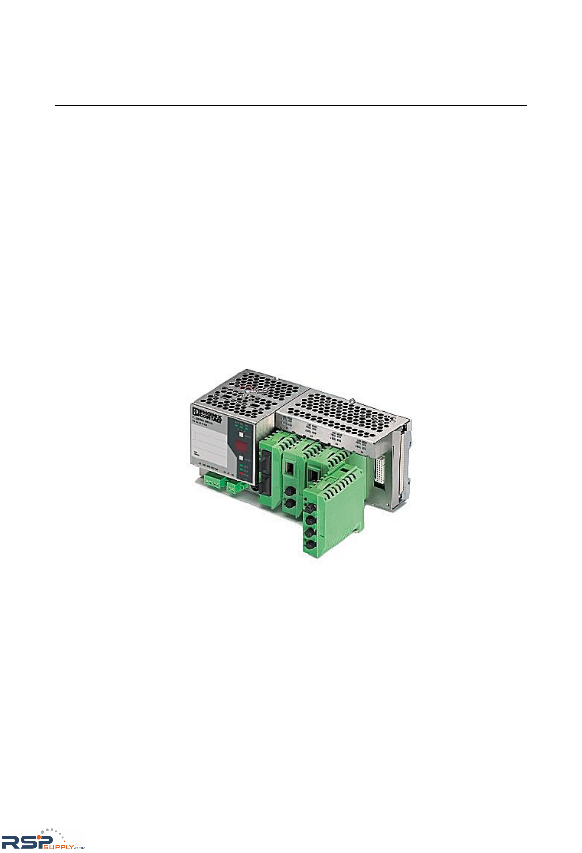
Depending on your requirements, you can create a compact switch for the control cabinet
(with convenient connections on the front) or a switch for the terminal box (with connections
at the bottom). It is also possible to add a glass fiber interface or extend your existing station
from 8/16 ports to a maximum of 24 ports.
Figure 1-2 Possible system hardware
PROFINET The switches can be operated in PC WorX and Step 7 environments as conformance
class B PROFINET IO devices. Connections to PLC systems can be easily implemented for
diagnostic and communication applications.
RSPSupply - 1-888-532-2706 - www.RSPSupply.com
http://www.RSPSupply.com/p-14178-Phoenix-Contact-2832357-FL-IF-2TX-VS-RJ-D-Media-Module-for-Modular-Switch.aspx
Page 13

The Modular Managed Switch System (MMS) and the Managed Compact Switch (MCS)
6874_en_16 PHOENIX CONTACT 1-3
Ethernet/IP In the Ethernet/IP environment the switches support the IGMP snooping function and
multicast filtering.
Smart mode For easy configuration, the switches support Smart mode in which the operating state can
be changed without WBM.
Features and fields of application of the MMS and MCS
– Increased network performance by filtering data traffic:
- Local data traffic remains local.
- The data volume in the network segments is reduced.
– Easy network expansion and network configuration.
– Coupling segments with different transmission speeds.
Automatic detection of 10 Mbps or 100 Mbps data transmission rate with auto crossing.
– Increased availability through the use of redundant transmission paths with Rapid
Spanning Tree. Support of various topologies and meshed structures as well as ring
topologies with special ring detection. Fast switch-over times with RSTP fast ring
detection.
– Configuration of switches using web-based management, SNMP, Telnet or locally via
a V.24 (RS-232) interface.
– Multicast filtering (static and dynamic).
– IGMP snooping, optional querier function.
– VLAN support according to 802.1Q (32 VLANs).
– Port security functions.
– Access control for web-based management (WBM).
– Optimum support of the PROFINET RT and Ethernet/IP automation
protocols.
– Integration in PROFINET environments.
– Topology detection using LLDP (Link Layer Discovery Protocol).
– Address assignment via BootP, DHCP, DCP or statically.
– Address assignment using DHCP option 82 relay agent.
– MMS: Support of Power over Ethernet (PoE).
– MMS: Support of POF-SCRJ
– S upport of the Med ia R edu ndancy Protocol (MR P), both as a client a nd a s th e manager
(in conjunction with the "FL IF MEM 2TX-D/MRM" interface module for the MMS or the
"FL MEM PLUG/MRM" interface module for the MCS). The MRP ring can thus be
created using any MMS/MCS ports, they simply have to be defined.
1.2.1 System components (MMS)
Central element
FL SWITCH MM HS
The head station is the central element of the Modular Managed Switch System. It contains
all the management functions, and the interface modules provide it with the desired
interfaces to the network. Up to two extension modules can be connected to a head station,
which means that the maximum system configuration comprises 24 Ethernet ports.
RSPSupply - 1-888-532-2706 - www.RSPSupply.com
http://www.RSPSupply.com/p-14178-Phoenix-Contact-2832357-FL-IF-2TX-VS-RJ-D-Media-Module-for-Modular-Switch.aspx
Page 14
FL SWITCH MM HS
1-4
PHOENIX CONTACT 6874_en_16
FL SWITCH MM HS/M Thanks to certification according to Germanischer Lloyd (GL Certificate No. 2427504 HH),
the FL SWITCH MM HS/M head station, the FL MXT/M extension module, and some of the
available interface modules have been approved for shipbuilding and
off/onshore applications. Please observe the list of GL-certified components on page 12-9.
Please also observe the notes for supply voltage connection on page 2-11.
Extension module
FL MXT
An extension module provides another 8 ports, which can be individually equipped with
interface modules. A maximum of 2 extension modules can be connected to the head
station. The maximum system configuration therefore comprises 24 ports.
FL MXT/M The FL MXT/M extension module is approved for shipbuilding and off/onshore applications
thanks to its certification according to GL (Certificate No. 2427504 HH).
Interface modules
FL IF ...
Interface modules provide the desired interface to the network. The two outlet directions,
the various types of media supported, and the port density of two ports per interface module
provide a high degree of flexibility in terms of the system configuration.
NOTE: Always switch off the supply voltage before inserting or removing extension
modules (FL MXT).
Do not connect more than two extension modules (FL MXT) to one head station.
It is not possible to operate the extension modules without the head station.
Please observe the list of GL-certified components on page 12-9.
RSPSupply - 1-888-532-2706 - www.RSPSupply.com
http://www.RSPSupply.com/p-14178-Phoenix-Contact-2832357-FL-IF-2TX-VS-RJ-D-Media-Module-for-Modular-Switch.aspx
Page 15

The Modular Managed Switch System (MMS) and the Managed Compact Switch (MCS)
6874_en_16 PHOENIX CONTACT 1-5
1.2.2 MMS firmware versions and their functions
Firmware Version 1.03 provides the standard switch functions.
In addition, firmware Version 1.11 supports the Spanning Tree redundancy mechanism.
Firmware 2.03 offers the following additional functions:
–Multicast filter mechanisms (maximum of 20 multicast groups)
– IGMP snooping and querier function
– Memory module support
Firmware 2.10 offers the following additional functions:
– Auto-refresh of various WBM pages
– POF and FX interface module support
– Extensive support and improved configuration handling of the memory module
– Extended multicast filtering (multicast transmitters are detected and added to multicast
groups)
– Extended IGMP snooping and IGMP query function (switch passively reads IGMP
membership reports, creates corresponding multicast groups, and sends IGMP
queries to multicast groups)
– Visualization of port capacity
– Port prioritization
Firmware 3.04 offers the following additional functions:
– VLAN support
– Rapid Spanning Tree support
– Security options (port-based security and access control for WBM)
– Optimization of the password concept
– Event table (logging of important events)
– Representation of MAC address table in WBM
Firmware 4.03 offers the following additional functions:
– Optimized Rapid Spanning Tree Protocol (RSTP) (improved switch-over times)
–Fast ring detection
– Large tree support
– Support of LLDP topology detection
– DHCP support
– DHCP with option 82 relay agent
– PROFINET device function and DCP
– Support of Power over Ethernet (IEEE 802.3af)
– Simplified port configuration
–IGMP query Version1 and 2
Firmware 4.50 offers the following additional functions:
– Support of the POF-SCRJ interface module and corresponding diagnostics
– SNMP traps can be disabled individually
– The VLAN for management can be set: VLAN ID to manage (web, SNMP, ping, IGMP
query) the switch in "VLAN Tagging" mode
– DHCP relay agent can be disabled according to the port
– PROFINET alarms and configuration comparison
– Fast aging on link down
RSPSupply - 1-888-532-2706 - www.RSPSupply.com
http://www.RSPSupply.com/p-14178-Phoenix-Contact-2832357-FL-IF-2TX-VS-RJ-D-Media-Module-for-Modular-Switch.aspx
Page 16

FL SWITCH MM HS
1-6
PHOENIX CONTACT 6874_en_16
– Extended LED diagnostics (identification of the switch in the PROFINET environment
and detection of the "Missing IP parameter following restart" status)
– PoE traps (when the PoE status changes)
– Test traps to check communication
– Deletion of the MAC address table from WBM and SNMP
Firmware 4.60 offers the following additional functions:
– Support of the Media Redundancy Protocol, both as a client and as the manager
– Extended PROFINET IO device function
– Support of up to 128 multicast groups, of which up to 20 are static groups
Firmware 4.70a offers the following additional functions:
– Support of time synchronization using SNTP
– Support of the PDEV function for the PROFINET environment
– Support of Smart mode for easily selecting the operating mode
RSPSupply - 1-888-532-2706 - www.RSPSupply.com
http://www.RSPSupply.com/p-14178-Phoenix-Contact-2832357-FL-IF-2TX-VS-RJ-D-Media-Module-for-Modular-Switch.aspx
Page 17
The Modular Managed Switch System (MMS) and the Managed Compact Switch (MCS)
6874_en_16 PHOENIX CONTACT 1-7
1.2.3 Firmware functions and the required hardware (MMS)
1.2.4 Device view (MMS)
1.2.4.1 Front view of the head station
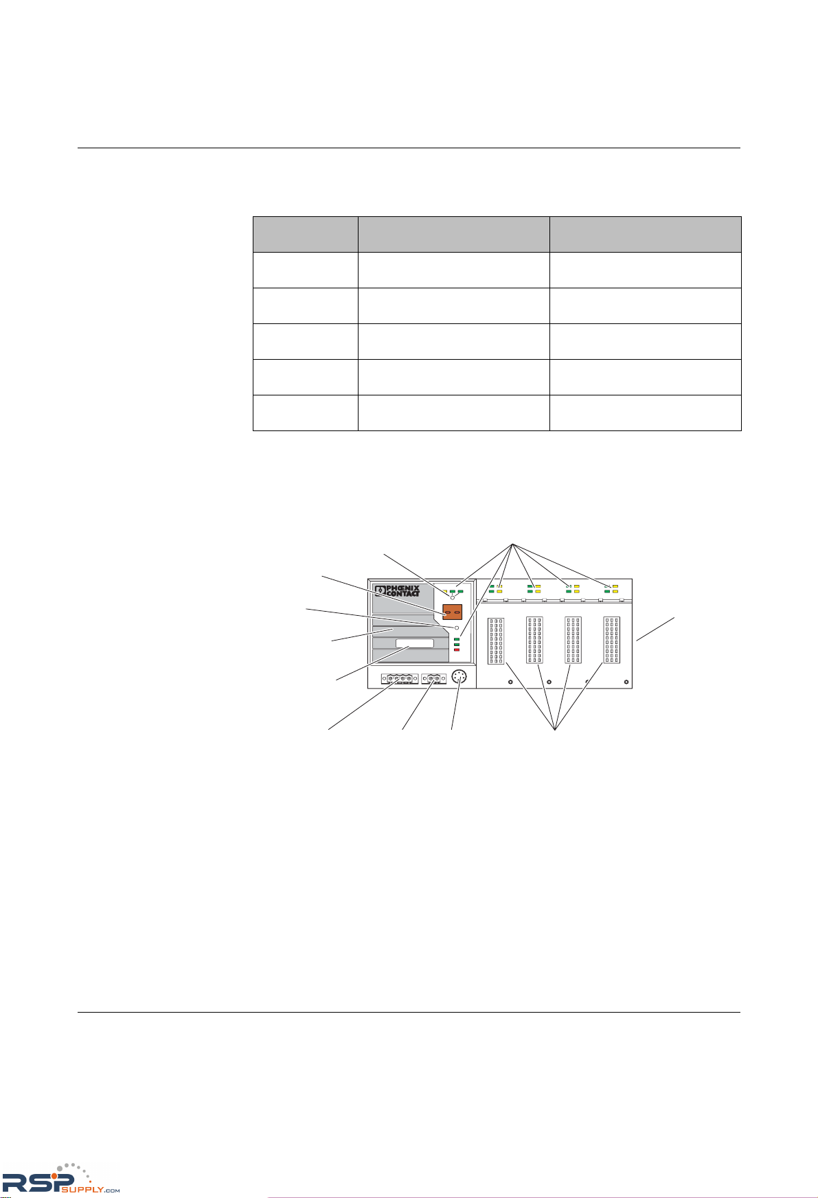
Figure 1-3 Front view of the head station
– Diagnostic/status indicators
Important information is displayed directly on the device. Each port has two LEDs. The
left-hand LED always indicates the "LINK", while the right-hand LED display is set with
the function switch.
– Function switch for LEDs
Th e MODE functio n sw itc h can be us ed t o specify which information is displayed by the
second port-specific LED. The three LEDs above the switch indicate the selected
mode. This information is then displayed by all port-specific LEDs (see also example
on page 1-13).
– Connection for extension module (FL MXT)
Connect the first of a maximum of two extension modules here.
Table 1-1 Functions and the required hardware
Function Required hardware for the
head station
Required hardware for the
extension modules
Standard switch
functions
Hardware Version ≥ 3
(includes system bus Version 4.1)
Hardware Version ≥ 2
(includes system bus Version 3.1)
Memory module
support
Hardware Version ≥ 4
(includes system bus Version 4.2)
Hardware Version ≥ 2
(includes system bus Version 3.1)
PoE module support
Hardware Version ≥ 6
(includes system bus Version 5.0)
Hardware Version ≥ 4
(includes system bus Version 4.0)
POF-SCRJ module support
Hardware Version ≥ 6
(includes system bus Version 5.0)
Hardware Version ≥ 4
(includes system bus Version 4.0)
MRP module
support
Hardware Version ≥ 6
(includes system bus Version 5.0)
Hardware Version ≥ 4
(includes system bus Version 4.0)
Slots for interface
modules
Mini-DIN
V.24 (RS-232)
Alarm
contact
Supply voltage
connection
Diagnostic
display
Diagnostic/status
indicators
Reset
button
Function switch
for LEDs
Connection for
extension module
(outgoing system
interface)
67961010
Labeling field
US1
US2
Fail
Reset
MODE
ACT
100
FD
FL SWITCH MM HS
Ord.No. 28 32 32 6
US2US1
GND GND
R1 R2
00A0451BDD
MAC
Address
MAC address
LNK
MODE
1
2
X1
LNK
MODE
1
2
X2
LNK
MODE
1
2
X3
LNK
MODE
1
2
X4
V.24
RSPSupply - 1-888-532-2706 - www.RSPSupply.com
http://www.RSPSupply.com/p-14178-Phoenix-Contact-2832357-FL-IF-2TX-VS-RJ-D-Media-Module-for-Modular-Switch.aspx
Page 18
FL SWITCH MM HS
1-8
PHOENIX CONTACT 6874_en_16
– Slots for interface modules
This is where the various interface modules (each with two ports) are inserted and
locked in place.
– Mini-DIN V.24 (RS-232)
V.24 (RS-232) interface in Mini-DIN format for local configuration via the serial
interface.
–Alarm contact
The floating alarm contact can be connected here via a 2-pos. COMBICON connector.
– Supply voltage connection
The supply voltage can be connected via the 4-pos. COMBICON connector
(redundancy is optional).
– Reset button
– Diagnostic display
Various operating states or error states can be displayed here. For a list of possible
codes, please refer to page 1-14.
1.2.4.2 Front view of the extension module
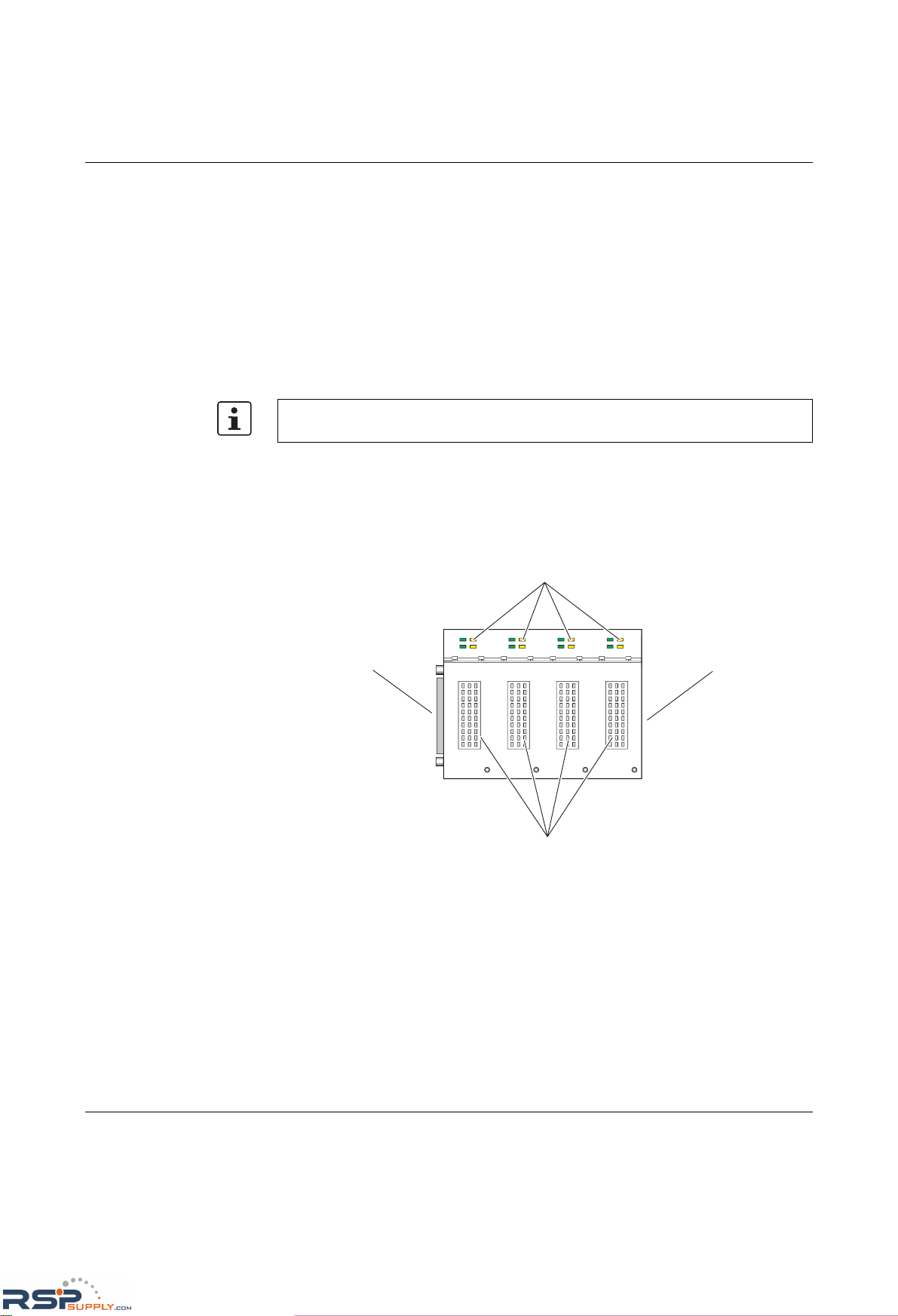
Figure 1-4 Front view of the extension module
– Diagnostic/status indicators
Important information is displayed directly on the device.
– Connection for second extension module
Connect the second extension module here.
– Connection for interface modules
This is where the various interface modules are inserted and locked in place.
In order to prevent an accidental MMS reset, the reset button must be held down for a few
seconds before it triggers a reset.
67961011
Diagnostic/status
indicators
Connection for first
xtension module/head
station (incoming
system interface)
LNK
MODE
1
2
X1
LNK
MODE
1
2
X2
LNK
MODE
1
2
X3
LNK
MODE
1
2
X4
Slots for interface modules
Connection for second
extension module
(outgoing system
interface)
RSPSupply - 1-888-532-2706 - www.RSPSupply.com
http://www.RSPSupply.com/p-14178-Phoenix-Contact-2832357-FL-IF-2TX-VS-RJ-D-Media-Module-for-Modular-Switch.aspx
Page 19
The Modular Managed Switch System (MMS) and the Managed Compact Switch (MCS)
6874_en_16 PHOENIX CONTACT 1-9
– Slot for first extension module/head station
Connect this extension module either to a head station or to the first extension module
here.
1.2.4.3 View of the interface modules (example)
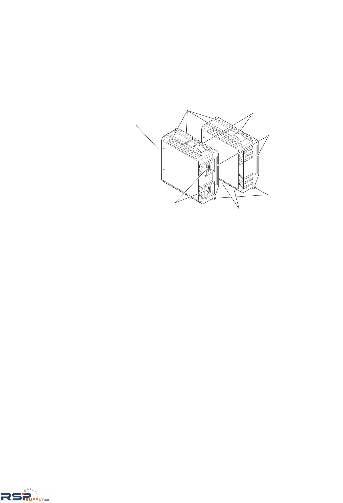
Figure 1-5 View of the interface modules (example)
– Connection for extension module/head station
This connector is used to connect the interface module and the extension module or the
head station.
–Guide bars
These bars aid installation and hold the interface modules securely in place.
– Positive latches
These latches must be pressed in order to remove the interface module (previous
versions used mounting screws).
–Ethernet ports
These are the ports for the various interfaces and connection directions.
– Marking groove for Zackband ZBF ...
– Mounting screws to lock the interface modules in place.
68741002
Guide bars
Positive latches
Ethernet ports,
connection on the front
Ethernet ports,
connection on the bottom
Connection for head
station/extension module
Marking groove
for Zackband ZBF
Mounting screws
RSPSupply - 1-888-532-2706 - www.RSPSupply.com
http://www.RSPSupply.com/p-14178-Phoenix-Contact-2832357-FL-IF-2TX-VS-RJ-D-Media-Module-for-Modular-Switch.aspx
Page 20
FL SWITCH MM HS
1-10
PHOENIX CONTACT 6874_en_16
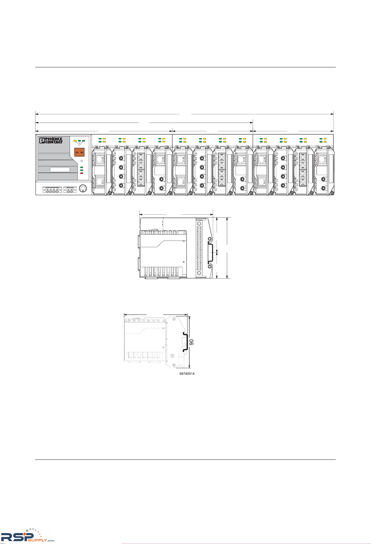
1.2.5 Dimensions of the Modular Managed Switch System
for normal operation
Figure 1-6 MMS housing dimensions in millimeters
Housing dimensions of the converter board with interface module
Housing width: 67 mm
Figure 1-7 Housing dimensions of the FL CB IF converter board
LNK
MODE
1
2
X1
LNK
MODE
1
2
X2
LNK
MODE
1
2
X3
LNK
MODE
1
2
X4
US1
US2
Fail
Reset
MODE
ACT
100
FD
FL SWITCH MM HS
Ord. No.28 32 32 6
US2US1
GND GND
R1 R2
00A0451BDD
MAC
Address
V.24
LNK
MODE
1
2
X1
LNK
MODE
1
2
X2
LNK
MODE
1
2
X3
LNK
MODE
1
2
X4
LNK
MODE
1
2
X1
LNK
MODE
1
2
X2
LNK
MODE
1
2
X3
LNK
MODE
1
2
X4
68740007
214
127 127
341
114.5
5540
95
68740013
468
110.5
RSPSupply - 1-888-532-2706 - www.RSPSupply.com
http://www.RSPSupply.com/p-14178-Phoenix-Contact-2832357-FL-IF-2TX-VS-RJ-D-Media-Module-for-Modular-Switch.aspx
Page 21
The Modular Managed Switch System (MMS) and the Managed Compact Switch (MCS)
6874_en_16 PHOENIX CONTACT 1-11
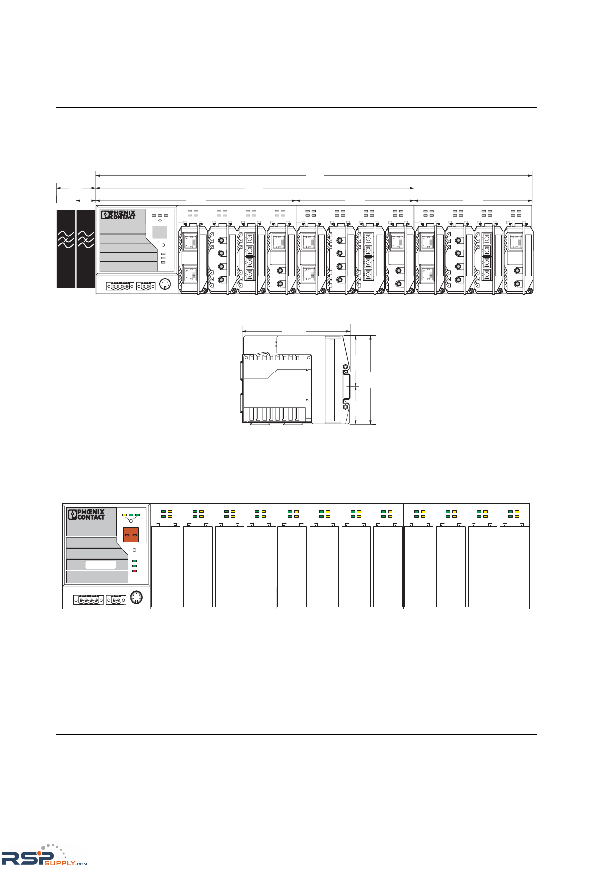
1.2.6 Dimensions of the Modular Managed Switch System
for GL-certified operation
Figure 1-8 MMS housing dimensions in millimeters
1.2.7 Assignment of ports to slots
Figure 1-9 Assignment of ports to slots
68740007
214
127 127
341
40
NEF
1- 3
NEF
1- 3
25
55
95
114.5
50
468
68740049
L N K M O D E
1
2
X 1
L N K M O D E
1
2
X 2
L N K M O D E
1
2
X 3
L N K M O D E
1
2
X 4
U S 1
U S 2
F a il
R e s e t
M O D E
A C T 1 0 0 F D
F L S W I T C H M M H S
O r d . N o . 2 8 3 2 3 2 6
U S 2U S 1 G N D G N D R 1 R 2
0 0 A 0 4 5 1 B D D
M A C
A d d r e s s
V .2 4
L N K M O D E
1
2
X 1
L N K M O D E
1
2
X 2
L N K M O D E
1
2
X 3
L N K M O D E
1
2
X 4
L N K M O D E
1
2
X 1
L N K M O D E
1
2
X 2
L N K M O D E
1
2
X 3
L N K M O D E
1
2
X 4
6 8 7 4 0 0 2 8
P o r t
1
P o r t
2
P o r t
3
P o r t
4
P o r t
5
P o r t
6
P o r t
7
P o r t
8
P o r t
9
P o r t
1 0
P o r t
1 1
P o r t
1 2
P o r t
1 3
P o r t
1 4
P o r t
1 5
P o r t
1 6
P o r t
1 7
P o r t
1 8
P o r t
1 9
P o r t
2 0
P o r t
2 1
P o r t
2 2
P o r t
2 3
P o r t
2 4
RSPSupply - 1-888-532-2706 - www.RSPSupply.com
http://www.RSPSupply.com/p-14178-Phoenix-Contact-2832357-FL-IF-2TX-VS-RJ-D-Media-Module-for-Modular-Switch.aspx
Page 22
FL SWITCH MM HS
1-12
PHOENIX CONTACT 6874_en_16
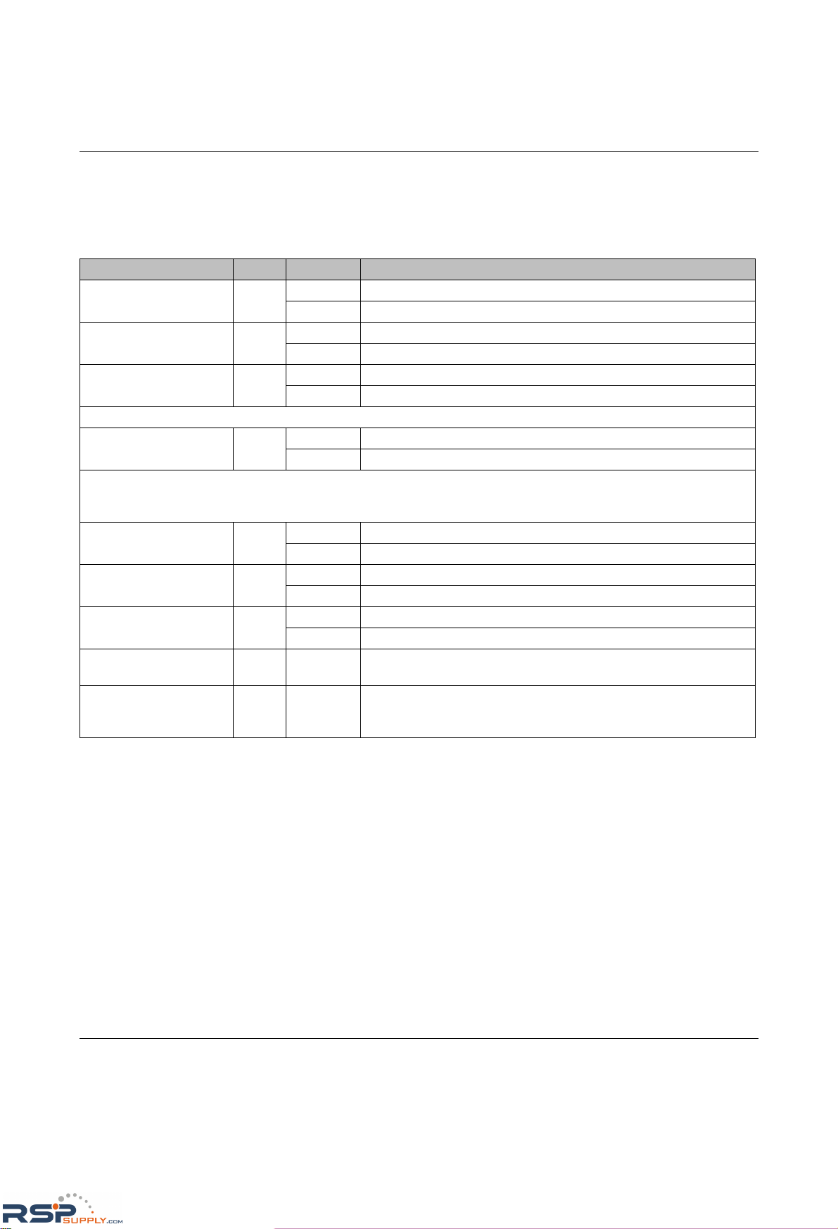
1.3 Status and diagnostic indicators
1.3.1 LEDs on the switch and the MMS extension module
Des. Color Status Meaning
US1 Green ON Supply voltage 1 in the tolerance range
OFF Supply voltage 1 too low
US2 Green ON Supply voltage 2 in the tolerance range
OFF Supply voltage 2 too low
FAIL Red ON Alarm contact open, i.e., an error has occurred
OFF Alarm contact closed, i.e., an error has not occurred
A Link LED is located above the interface module slot for each port
LNK
(Link)
Green ON Link active
OFF Link inactive
A second LED is provided above the interface module slot for each port on the MMS and on the front of the housing on the
MCS. The function of the second LED (MODE) for each port can be set using a switch on the device, which controls all ports
(see also example below). There are three options:
ACT
(Activity)
Green ON Sending/receiving telegrams
OFF Not sending/receiving telegrams
100 Green ON 100 Mbps
OFF 10 Mbps if Link LED is active
FD
(Duplex)
Green ON Full duplex
OFF Half duplex if Link LED is active
ACT and 100 and FD
simultaneously
Green Flashing PROFINET device identification
ACT or 100 or FD
(selected by mode
switch)
Green Flashing No IP parameter present following restart
RSPSupply - 1-888-532-2706 - www.RSPSupply.com
http://www.RSPSupply.com/p-14178-Phoenix-Contact-2832357-FL-IF-2TX-VS-RJ-D-Media-Module-for-Modular-Switch.aspx
Page 23
The Modular Managed Switch System (MMS) and the Managed Compact Switch (MCS)
6874_en_16 PHOENIX CONTACT 1-13
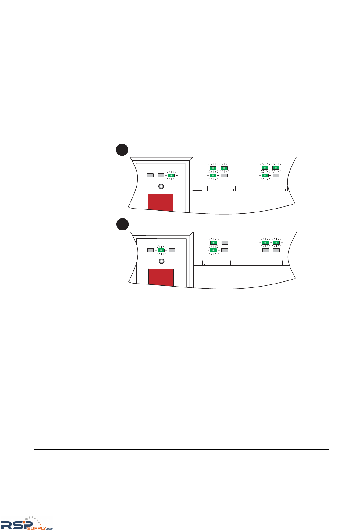
Example:
In Figure 1-10, the LED indicators have the following meaning (see also "Assignment of
ports to slots" on page 1-11):
A: The switch has been set to display the duplex mode; the mode LEDs now indicate that
port 1 and port 3 are in full duplex mode and port 2 and port 4 are in half duplex mode.
B: The switch has been set to display the data transmission rate; the mode LEDs now
indicate that port 1 and port 2 are operating at 10 Mbps, port 3 is operating at 100 Mbps,
and port 4 is not operating at all.
Figure 1-10 Example for status indicators
A C T F D1 0 0
1
2
L N K M O D E
X 1
1
2
L N K M O D E
X 2
M O D E
A
B
A C T F D1 0 0
1
2
L N K M O D E
X 1
1
2
L N K M O D E
X 2
M O D E
6 8 7 4 0 0 0 1
RSPSupply - 1-888-532-2706 - www.RSPSupply.com
http://www.RSPSupply.com/p-14178-Phoenix-Contact-2832357-FL-IF-2TX-VS-RJ-D-Media-Module-for-Modular-Switch.aspx
Page 24
FL SWITCH MM HS
1-14
PHOENIX CONTACT 6874_en_16
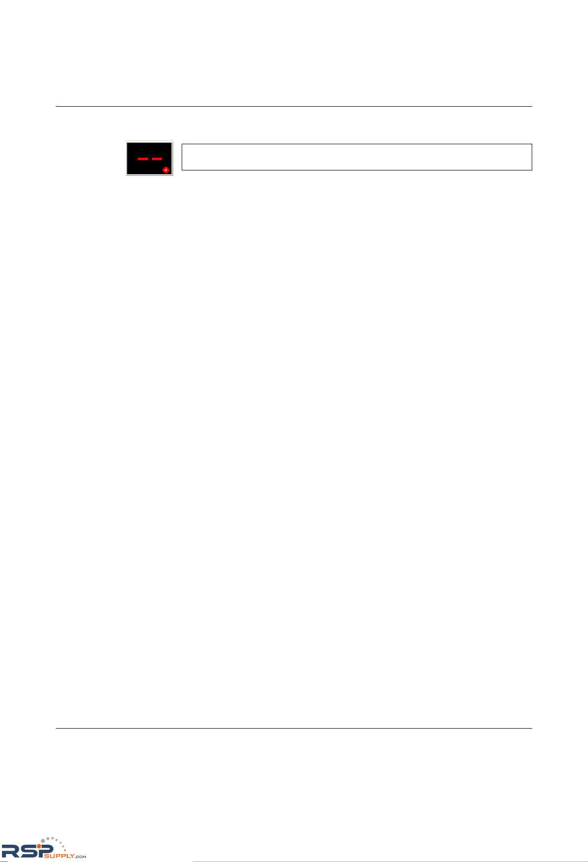
1.3.2 Meaning of the 7-segment display (MMS)
If the MMS has established a PROFINET connection, a dot appears in the bottom-right
corner of the display.
RSPSupply - 1-888-532-2706 - www.RSPSupply.com
http://www.RSPSupply.com/p-14178-Phoenix-Contact-2832357-FL-IF-2TX-VS-RJ-D-Media-Module-for-Modular-Switch.aspx
Page 25
The Modular Managed Switch System (MMS) and the Managed Compact Switch (MCS)
6874_en_16 PHOENIX CONTACT 1-15
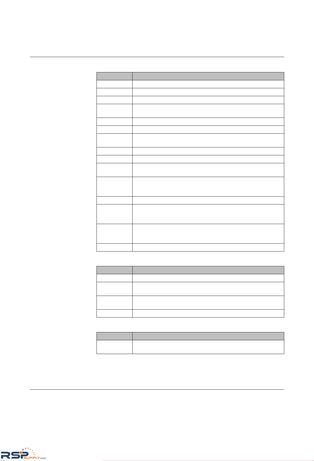
During error-free operation:
Messages during operation with the memory module:
Messages during operation with the MRP memory module:
Display Meaning
xx. PROFINET connection established between controller and MMS
bo Extracting/starting firmware (boot)
01 Sending BootP requests
SC Parameterization data being saved to the plug-in memory and the head
station.
03 Downloading firmware via TFTP
04 Loading firmware in the Flash memory that was loaded via the network
05 The recently loaded firmware was successfully saved in the Flash mem-
ory
_ _ Initializing firmware
-- Firmware running
rb A reset has been triggered via SNMP, WBM or V.24 (RS-232), the device
is preparing to restart (reboot)
rC After a device configuration update, "rC" (reconfiguration) may appear in
the display after a restart. This means that the firmware automatically
adapts the new configuration and then restarts the switch again.
Pb A port blocked by the port security function is indicated with "Pb".
dP The device is operated as a PROFINET IO device and is waiting for
startup using a PROFINET controller. The device cannot be accessed via
an IP address.
"00" alternates
with another
display
In PROFINET mode, the engineering tool called the "flashing" function.
SP Spanning Tree initialization active
Display Meaning
0P Parameterization data being read from the plug-in memory
EC Equal configuration - the configurations on the m emo ry m odule and in the
head station are the same
dC Different configuration - the configurations on the memory module and in
the head station are different
0C The memory module is empty
Display Meaning
LF Loop Failure - the MRP manager has detected an error in the redundant
ring
RSPSupply - 1-888-532-2706 - www.RSPSupply.com
http://www.RSPSupply.com/p-14178-Phoenix-Contact-2832357-FL-IF-2TX-VS-RJ-D-Media-Module-for-Modular-Switch.aspx
Page 26
FL SWITCH MM HS
1-16
PHOENIX CONTACT 6874_en_16
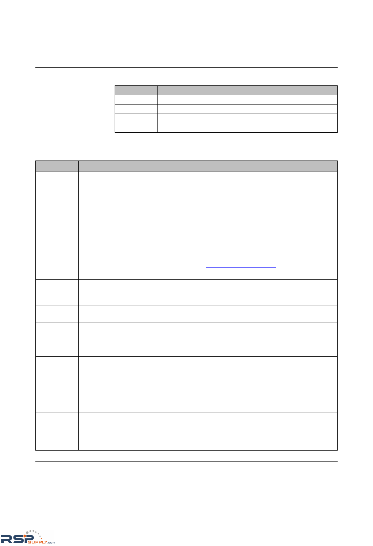
Messages in Smart mode:
In the event of an error:
Display Meaning
S1 Exit Smart mode without changes
S2 Reset to default settings
S3 Set PROFINET mode
S4 Set Ethernet/IP mode
Display Meaning Remedy
16 The device software (firmware) is
faulty
– Update the firmware via the serial interface.
17 Firmware transfer via TFTP or
Xmodem failed (display changes
from "03" to "17")
– Check the physical connection.
– Establish a point-to-point connection.
– Make sure that the file (with the specified file name) exists and
is in the correct directory.
– Check the IP address of the TFTP server.
– Activate the TFTP server.
– Repeat the download.
19 File transfer was completed suc-
cessfully, but the file is not a valid
firmware version for the Modular
Managed Switch System
– Provide a valid firmware version with the previously specified
file name
(Internet: www.phoenixcontact.com
).
– Repeat the download.
80 An error has occurred in the firm-
ware
– Restart the device (power up or reset).
– Make sure that the IP address is not used more than once in the
same network.
87 More than one parameterization
memory has been plugged in.
– Remove all but one of the memory modules and execute a
reset.
89 The switch is or was in an excep-
tional situation
– Restart the device.
– Check your network for configuration errors, loops, loose
contacts, poor line quality, faulty network interfaces.
– Make sure that there are no Denial of Service attacks.
Li Link monitoring has detected at
least one faulty link
– Check the cables/connectors.
– In web-based management, check at which port link monitoring
(see page 4-27) is indicating an error.
– Restore the data connection to this port or deactivate link
monitoring for this port.
– Check the correct position of the interface module on the head
station or on the extension module.
Cd The switch is operating as a
PROFINET IO device. The configuration of the switch and the configuration transmitted by the PROFINET
engineering tool are different
– Set the desired configuration at the switch.
– Modify the control program so that it contains the existing
switch configuration.
RSPSupply - 1-888-532-2706 - www.RSPSupply.com
http://www.RSPSupply.com/p-14178-Phoenix-Contact-2832357-FL-IF-2TX-VS-RJ-D-Media-Module-for-Modular-Switch.aspx
Page 27
The Modular Managed Switch System (MMS) and the Managed Compact Switch (MCS)
6874_en_16 PHOENIX CONTACT 1-17
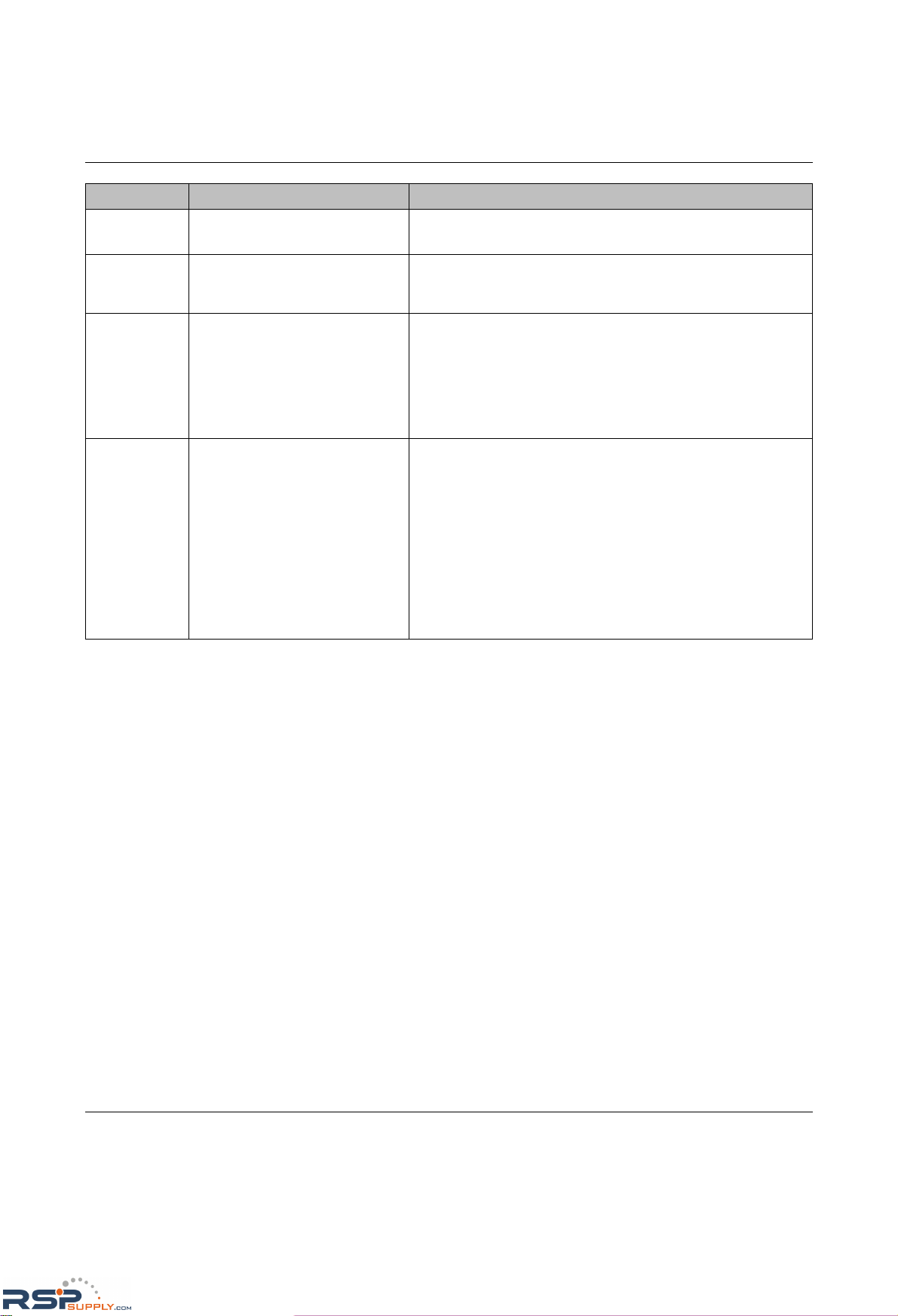
bF System bus error
(Bus Fail)
– Make sure that the extension modules are plugged in correctly.
– Restart the switch.
Po Power – Power over Ethernet monitoring has been activated on at least
one port and an error has occurred. Check the physical
connection at the PoE ports and the settings in WBM.
HS Hardware support – At least one interface module is inserted in the MMS that is not
fully supported by the MMS hardware version used. The
interface module transmits data, the management functions
are deactivated. The message appears for approximately ten
seconds on the display after a restart or after interface modules
have been inserted or removed. The interface module can be
used in unmanaged mode.
LF Loop Failure - the redundant ring
has been interrupted
– The redundant ring has been physically interrupted. Check the
physical connection.
– The switch configured as the redundancy manager did not find
a valid MRP module on the last device startup, there is no
redundant connection. Make sure that at least one switch is
configured in the MRP ring as the MRP manager and a valid
MRP module is plugged in.
– Incorrect ports. Make sure that the MRP ring is only created via
ports that are configured as an MRP port.
– Unsuitable switches. Make sure that all the switches that form
the MRP ring support MRP.
Display Meaning Remedy
RSPSupply - 1-888-532-2706 - www.RSPSupply.com
http://www.RSPSupply.com/p-14178-Phoenix-Contact-2832357-FL-IF-2TX-VS-RJ-D-Media-Module-for-Modular-Switch.aspx
Page 28
FL SWITCH MM HS
1-18
PHOENIX CONTACT 6874_en_16
1.4 Properties (MCS)
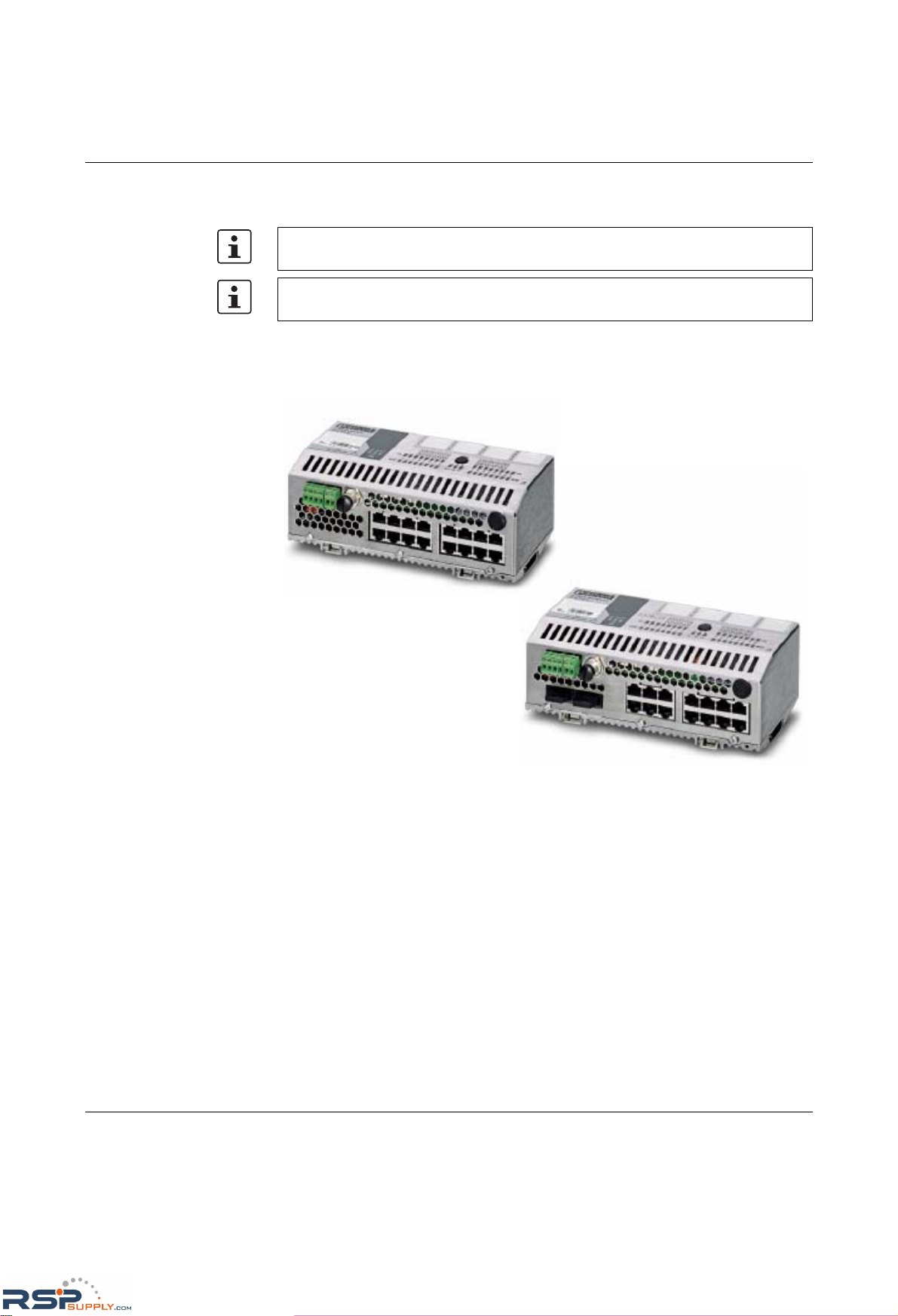
The Managed Compact Switch (MCS) is an Ethernet switch that is suitable for industrial
use. The MCS has 16 ports, but with two versions available:
– FL SWITCH MCS 16 TX with 16 RJ45 ports
– FL SWITCH MCS 14TX/2FX with 14 RJ45 ports and 2 multi-mode glass fiber FX ports
Figure 1-11 Versions of the Managed Compact Switch
1.4.1 Firmware versions and their functions (MCS)
Firmware Version 1.03 provides the standard switch functions.
In addition, firmware Version 1.11 supports the Spanning Tree redundancy mechanism.
Firmware 2.03 offers the following additional functions:
– Multicast filter mechanisms
– IGMP snooping and querier function
Firmware 2.10 offers the following additional functions:
– Auto-refresh of various WBM pages
– Extended multicast filtering (multicast transmitters are detected and added to multicast
groups)
The points under "Remedy" are recommendations; they do not all have to be carried out
for every error.
For all other message codes that are not listed here, please contact Phoenix Contact.
RSPSupply - 1-888-532-2706 - www.RSPSupply.com
http://www.RSPSupply.com/p-14178-Phoenix-Contact-2832357-FL-IF-2TX-VS-RJ-D-Media-Module-for-Modular-Switch.aspx
Page 29

The Modular Managed Switch System (MMS) and the Managed Compact Switch (MCS)
6874_en_16 PHOENIX CONTACT 1-19
– Extended IGMP snooping and IGMP query function (switch passively reads IGMP
membership reports, creates corresponding multicast groups, and sends IGMP
queries to multicast groups)
– Visualization of port capacity
– Port prioritization
Firmware 3.04 offers the following additional functions:
– VLAN support
– Rapid Spanning Tree support
– Security options (port-based security and access control for WBM)
– Optimization of the password concept
– Event table (logging of important events)
– Representation of MAC address table in WBM
Firmware 4.03 offers the following additional functions:
– Optimized Rapid Spanning Tree Protocol (RSTP) (improved switch-over times)
–Fast ring detection
– Large tree support
– Support of LLDP topology detection
– DHCP support
– DHCP with option 82 relay agent
– PROFINET device function and DCP
– Simplified port configuration
–IGMP query Version1 and 2
Firmware 4.50 offers the following additional functions:
– SNMP traps can be disabled individually
– The VLAN for management can be set: VLAN ID to manage (web, SNMP, ping, IGMP
query) the switch in "VLAN Tagging" mode
– DHCP relay agent can be disabled according to the port
– PROFINET alarms and configuration comparison
– Fast aging on link down
– Extended LED diagnostics (identification of the switch in the PROFINET environment
and detection of the "Missing IP parameter following restart" status)
– Test traps to check communication
– Deletion of the MAC address table from WBM and SNMP
Firmware 4.60 offers the following additional functions:
– Media Redundancy Protocol supported as a client
– Extended PROFINET IO device function
– Support of up to 128 multicast groups, of which up to 20 are static groups
Firmware 4.70 offers the following additional functions:
– Support of time synchronization using SNTP
RSPSupply - 1-888-532-2706 - www.RSPSupply.com
http://www.RSPSupply.com/p-14178-Phoenix-Contact-2832357-FL-IF-2TX-VS-RJ-D-Media-Module-for-Modular-Switch.aspx
Page 30

FL SWITCH MM HS
1-20
PHOENIX CONTACT 6874_en_16
– Support of the PDEV function for the PROFINET environment
– Support of Smart mode for easily selecting the operating mode
– MEM plug support
– MRP master function in conjunction with MEM PLUG/MRM
RSPSupply - 1-888-532-2706 - www.RSPSupply.com
http://www.RSPSupply.com/p-14178-Phoenix-Contact-2832357-FL-IF-2TX-VS-RJ-D-Media-Module-for-Modular-Switch.aspx
Page 31
The Modular Managed Switch System (MMS) and the Managed Compact Switch (MCS)
6874_en_16 PHOENIX CONTACT 1-21
1.4.2 Firmware functions and the required hardware (MCS)
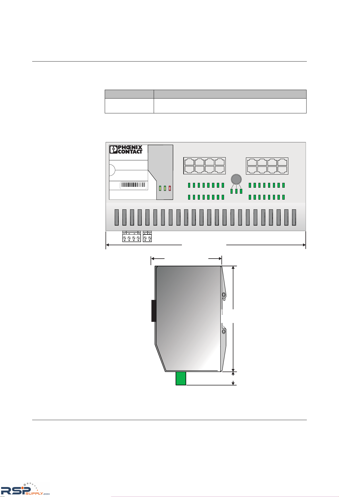
1.4.3 Dimensions of the MCS
Figure 1-12 Housing dimensions of the MCS in millimeters (inches); depth: 71 mm from
upper edge DIN rail
Table 1-2 Functions and the required hardware
Function Required hardware for the head station
MEM plug support Hardware Version ≥ 4
(includes system bus Version 4.2)
FL SWITCH MCS 16TX
Ord. No. 28 32 70 0
00.A0.45.1B.D2.1D
MAC
Address
1 3 57
2468
9
11
13
15
10
12
14
16
91610 11 12 13 14 15
1 82 3 4567
MODE
ACT
100
FD
US1US2
FAIL
X19
V.24
X17
US1 GND US2 GND
X18
R1 R2
95 mm / 3.74 in.
10 mm / 0.39 in.
71 mm / 2.795 in.
214 mm / 8.43 in.
70582003
RSPSupply - 1-888-532-2706 - www.RSPSupply.com
http://www.RSPSupply.com/p-14178-Phoenix-Contact-2832357-FL-IF-2TX-VS-RJ-D-Media-Module-for-Modular-Switch.aspx
Page 32
FL SWITCH MM HS
1-22
PHOENIX CONTACT 6874_en_16
1.4.4 Device view (MCS)
1.4.4.1 Front view/operating elements/slots for the MCS
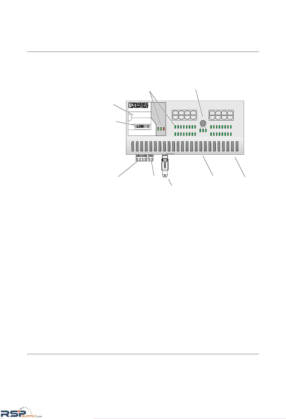
Figure 1-13 Front view/operating elements/slots for the MCS
– Diagnostic/status indicators
Important information is displayed directly on the device. Each port has two LEDs. The
top LED always indicates the "LINK", while the bottom LED display is set with the
function switch.
– Function switch for LEDs
Th e MODE functio n sw itc h can be us ed t o specify which information is displayed by the
second port-specific LED. The three LEDs below the switch indicate the selected
mode. This information is then displayed by all port-specific LEDs (see also example
on page 1-13).
– Mini-DIN V.24 (RS-232)
V.24 (RS-232) interface in Mini-DIN format for local configuration via the serial
interface.
–Alarm contact
The floating alarm contact can be connected here via a 2-pos. COMBICON connector.
– Supply voltage connection
The supply voltage can be connected redundantly via the 4-pos. COMBICON
connector as an option.
– Slot for MEM PLUG
FL SWITCH MCS 16TX
Ord.No. 28 32 70 0
00.A0.45.1B.D2.1D
MAC
Address
1357
2468
9
11
13
15
10
12
14 16
91610 11 12 13 14 15
18234567
MODE
ACT
100
FD
US1 US2
FAIL
X19
V.24
X17
US1 GND US2 GND
X18
R1 R2
Ethernet ports
Mini-DIN V.24
(RS-232)
Alarm
contact
Supply voltage
connection
Diagnostic/status
indicators
Function switch
for LEDs
Labeling field
MAC address
70562003
FL MEM PLUG
2891259
RSPSupply - 1-888-532-2706 - www.RSPSupply.com
http://www.RSPSupply.com/p-14178-Phoenix-Contact-2832357-FL-IF-2TX-VS-RJ-D-Media-Module-for-Modular-Switch.aspx
Page 33
Mounting and installation
6874_en_16 PHOENIX CONTACT 2-1
2 Mounting and installation
2.1 Mounting and removing the MMS head station or
MCS
Mount the head station/MCS on a clean DIN rail according to DIN EN 50 022
(e.g., NS 35 ... from Phoenix Contact). To avoid contact resistance only use clean,
corrosion-free DIN rails. Before mounting the modules, an end clamp (E/NS 35N, Order No.
08 00 88 6) should be mounted on the left-hand side next to the head station/MCS to stop
the modules from slipping on the DIN rail. The supplied ATP-ST-TWIN side cover (see "A"
in Figure 2-4) and the end clamp should only be mounted on the right-hand side once the
last extension module has been mounted.
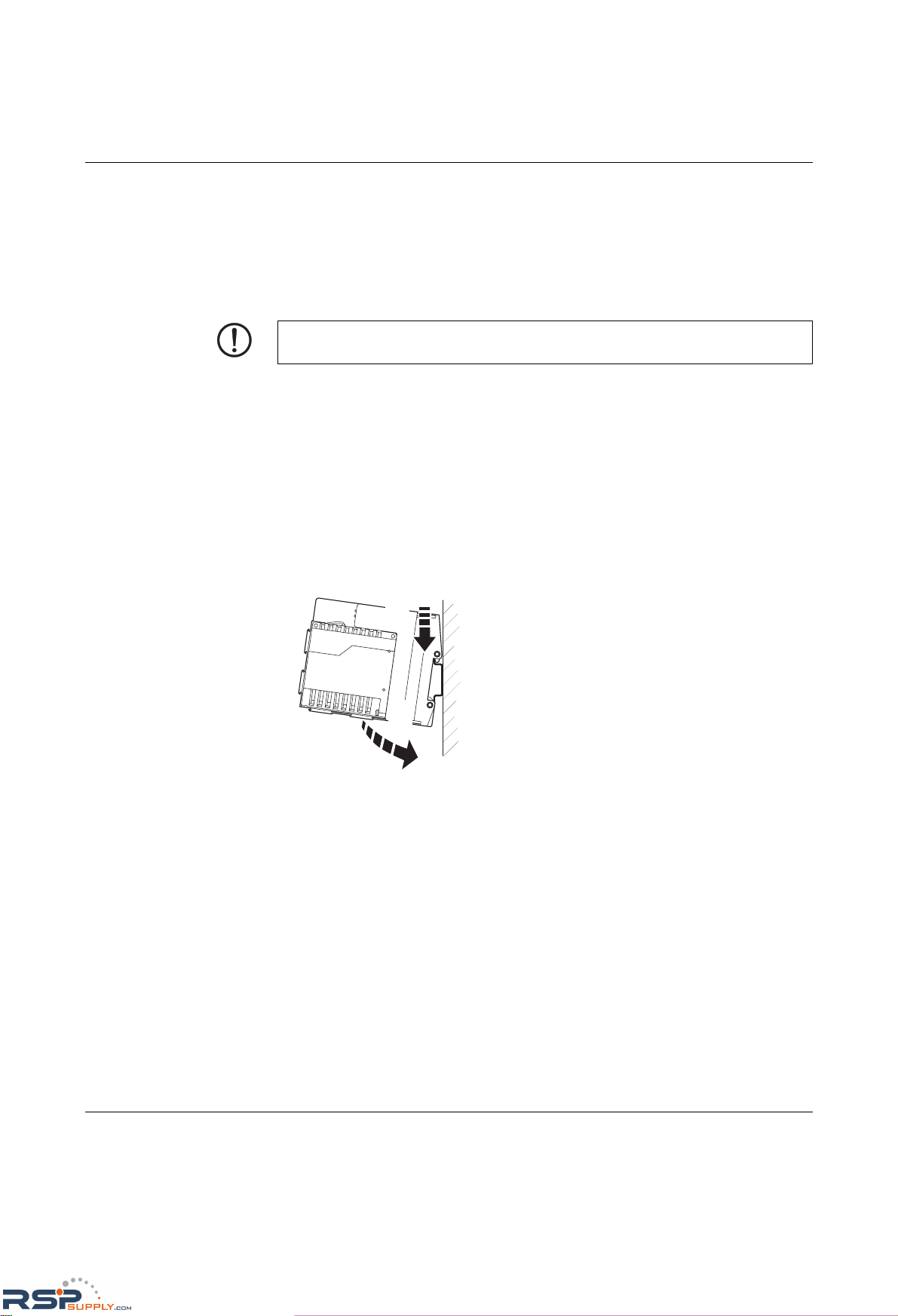
Mounting:
1. Place the module onto the DIN rail from above (A). The upper holding keyway must be
hooked onto the top edge of the DIN rail. Push the module from the front towards the
mounting surface (B).
Figure 2-1 Snapping the head station onto the DIN rail
2. Once the module has been snapped on properly, check that it is fixed securely on the
DIN rail. Check whether the positive latches are facing upwards, i.e., snapped on
correctly.
NOTE: Always switch off the supply voltage when mounting/removing the head
station/MCS and extension modules.
B
A
RSPSupply - 1-888-532-2706 - www.RSPSupply.com
http://www.RSPSupply.com/p-14178-Phoenix-Contact-2832357-FL-IF-2TX-VS-RJ-D-Media-Module-for-Modular-Switch.aspx
Page 34
FL SWITCH MM HS
2-2
PHOENIX CONTACT 6874_en_16
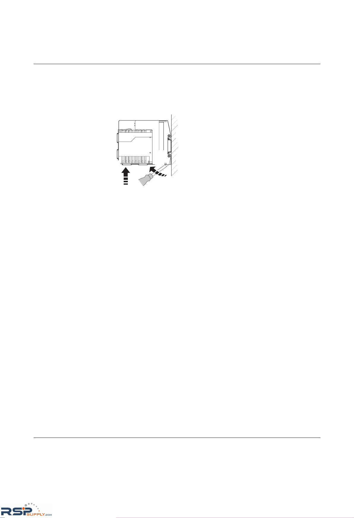
Removal:
1. Remove all plug-in connections or interface modules.
2. Pull down the positive latches using a suitable tool (e.g., screwdriver). Both positive
latches remain snapped out. Then swivel the bottom of the module away from the DIN
rail slightly (A). Next, lift the module upwards away from the DIN rail (B).
Figure 2-2 Removing the head station
A
B
RSPSupply - 1-888-532-2706 - www.RSPSupply.com
http://www.RSPSupply.com/p-14178-Phoenix-Contact-2832357-FL-IF-2TX-VS-RJ-D-Media-Module-for-Modular-Switch.aspx
Page 35
Mounting and installation
6874_en_16 PHOENIX CONTACT 2-3
2.2 Mounting and removing extension modules (MMS)
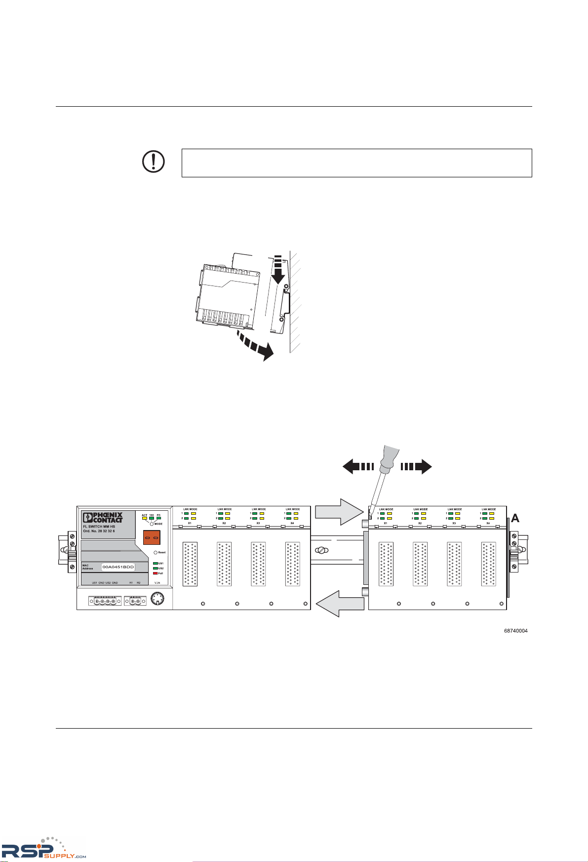
Mounting:
1. Place the module onto the DIN rail from above (A). The upper holding keyway must be
hooked onto the top edge of the DIN rail. Push the module from the front towards the
mounting surface (B). Check that the positive latches have snapped on properly.
Figure 2-3 Mounting extension modules
2. Now that the extension module is snapped onto the DIN rail, push it along the DIN rail
towards the head station, until the male connector/female connector of the modules are
interlatched and the sides of the modules lie flush with one another.
Figure 2-4 Mounting/removing extension modules
NOTE: Always switch off the supply voltage when mounting/removing the extension
modules.
B
A
Removal
Mounting
RSPSupply - 1-888-532-2706 - www.RSPSupply.com
http://www.RSPSupply.com/p-14178-Phoenix-Contact-2832357-FL-IF-2TX-VS-RJ-D-Media-Module-for-Modular-Switch.aspx
Page 36
FL SWITCH MM HS
2-4
PHOENIX CONTACT 6874_en_16
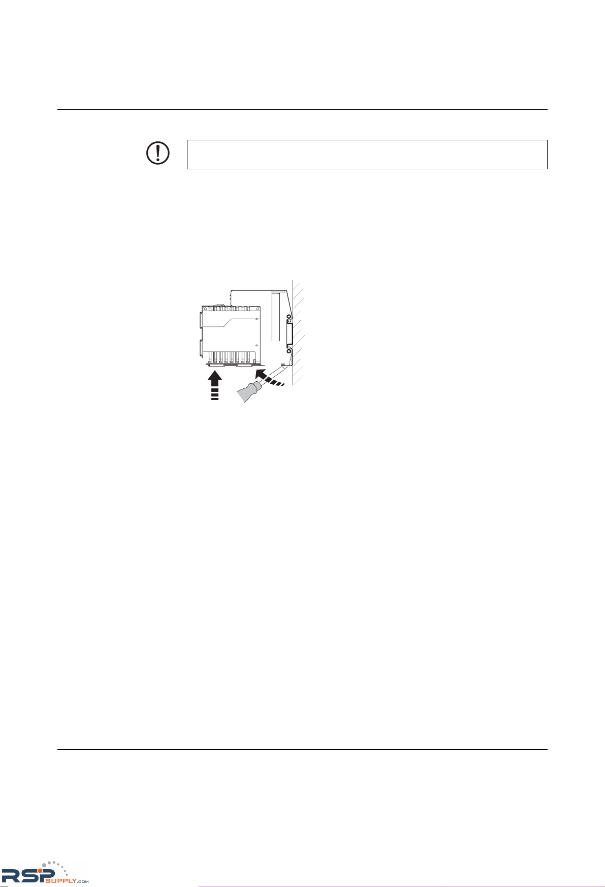
Removal:
1. Remove all plug-in connections or interface modules.
2. To release the plug-in connection for the system interface, insert a screwdriver in the
notch provided and use it to push the modules apart.
3. Push the right-hand extension module along the DIN rail to the right until the plug-in
contact is completely free.
4. Pull down the holding latches using a suitable tool (e.g., screwdriver).
5. Then swivel the bottom of the module away from the DIN rail slightly (A). Next, lift the
module upwards away from the DIN rail.
Figure 2-5 Removing extension modules
NOTE: Switch off the supply voltage before removing the extension modules.
A
B
RSPSupply - 1-888-532-2706 - www.RSPSupply.com
http://www.RSPSupply.com/p-14178-Phoenix-Contact-2832357-FL-IF-2TX-VS-RJ-D-Media-Module-for-Modular-Switch.aspx
Page 37
Mounting and installation
6874_en_16 PHOENIX CONTACT 2-5
2.3 Mounting and removing interface modules (MMS)
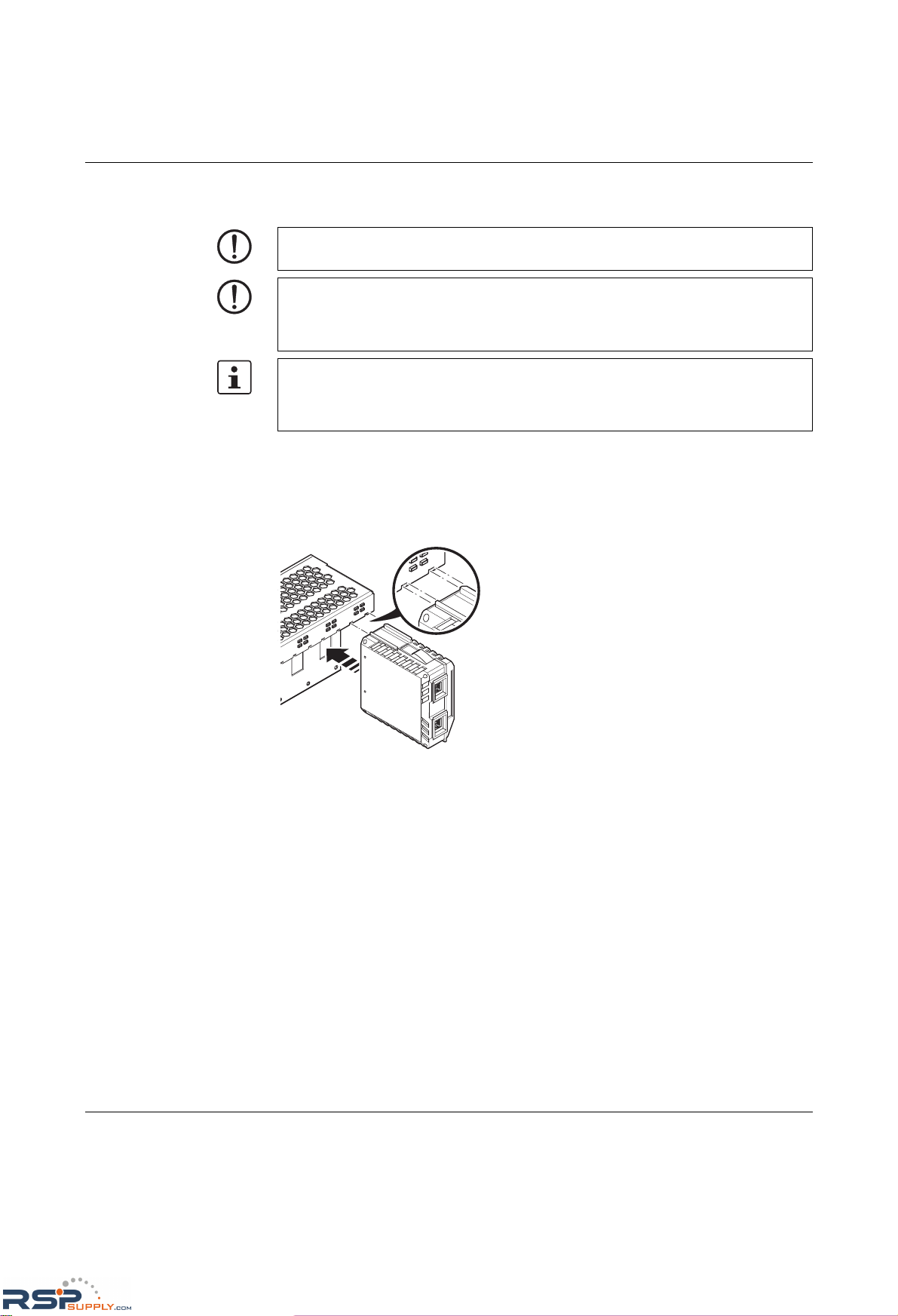
Mounting:
1. Insert the interface modules in the slots of the basic modules. The guide bars on the top
of the interface modules must be pushed into the guide slots of the basic module
without tilting them.
Figure 2-6 Mounting interface modules
2. Now push the interface modules towards the basic module until the connector and the
holding clamp are snapped into place.
NOTE: Ensure that the surface of the head station or extension module housing is clean.
NOTE: If the FL SWITCH MM HS with two FL MXT extension modules is additionally
operated with one FL IF MEM 2TX-D memory module and up to four FL IF POF SCRJ-D
interface modules at the same time, the arrangement according to Section "Arrangement
of the interface modules" on page 2-7 must be observed.
Hot plugging
When inserting and removing interface modules, you do not have to switch off the supply
voltage. The interface modules are detected automatically and logged to the network
management.
RSPSupply - 1-888-532-2706 - www.RSPSupply.com
http://www.RSPSupply.com/p-14178-Phoenix-Contact-2832357-FL-IF-2TX-VS-RJ-D-Media-Module-for-Modular-Switch.aspx
Page 38
FL SWITCH MM HS
2-6
PHOENIX CONTACT 6874_en_16
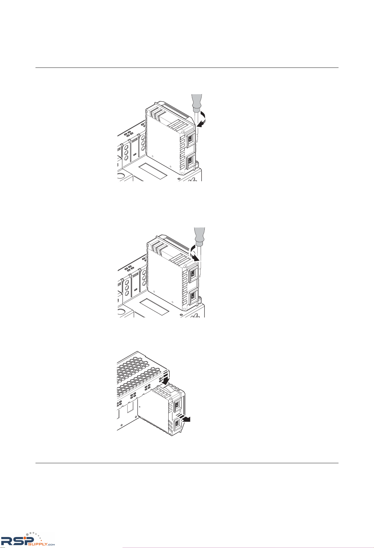
3. Secure the interface module using the screw on the bottom right-hand side of the
interface module.
Figure 2-7 Securing the interface module
Removal:
1. Remove the mounting screw.
Figure 2-8 Removing the mounting screw on interface modules
2. Press the positive latch (A) and pull out the module (B).
Figure 2-9 Removing the interface module
A
B
RSPSupply - 1-888-532-2706 - www.RSPSupply.com
http://www.RSPSupply.com/p-14178-Phoenix-Contact-2832357-FL-IF-2TX-VS-RJ-D-Media-Module-for-Modular-Switch.aspx
Page 39
Mounting and installation
6874_en_16 PHOENIX CONTACT 2-7
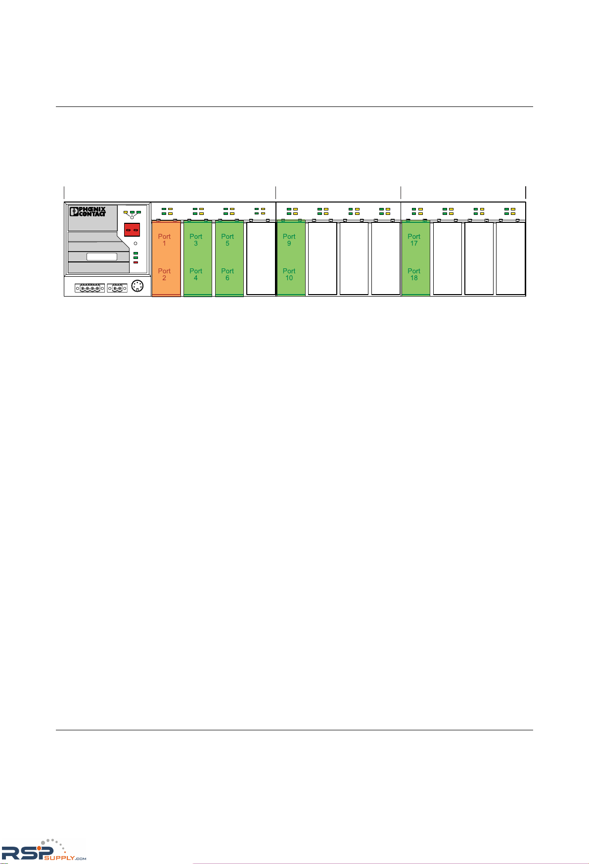
2.4 Arrangement of the interface modules
If the FL SWITCH MM HS with two FL MXT extension modules is additionally operated with
one FL IF MEM 2TX-D memory module and up to four FL IF POF SCRJ-D interface
modules at the same time, the following arrangement must be observed.
Figure 2-10 Arrangement of the interface modules
LNK
MODE
1
2
X1
LNK
MODE
1
2
X2
LNK
MODE
1
2
X3
LNK
MODE
1
2
X4
US1
US2
Fail
Reset
MODE
ACT
100
FD
FL SWITCH MM HS
Ord. No. 28 32 32 6
US2US1
GND GND
R1 R2
00A0451BDD
MAC
Address
V.24
LNK
MODE
1
2
X1
LNK
MODE
1
2
X2
LNK
MODE
1
2
X3
LNK
MODE
1
2
X4
LNK
MODE
1
2
X1
LNK
MODE
1
2
X2
LNK
MODE
1
2
X3
LNK
MODE
1
2
X4
Port
1
Port
2
Port
3
Port
4
Port
5
Port
6
Port
7
Port
8
Port
9
Port
10
Port
11
Port
12
Port
13
Port
14
Port
15
Port
16
Port
17
Port
18
Port
19
Port
20
Port
21
Port
22
Port
23
Port
24
MXT 2MXT 1MM HS
FL IF MEM
FL IF SCRJ
FL IF SCRJ
FL IF SCRJ
FL IF SCRJ
RSPSupply - 1-888-532-2706 - www.RSPSupply.com
http://www.RSPSupply.com/p-14178-Phoenix-Contact-2832357-FL-IF-2TX-VS-RJ-D-Media-Module-for-Modular-Switch.aspx
Page 40
FL SWITCH MM HS
2-8
PHOENIX CONTACT 6874_en_16
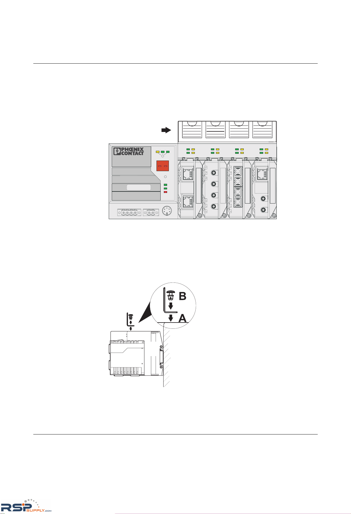
2.5 Mounting and removing the FL M LABEL labeling
field (accessories)
The FL M LABEL labeling field (Order No. 2891055) can be used to individually identify the
ports of the switch. The labeling field can be attached to the top of the device or to the MMS
extension modules.
Figure 2-11 Head station with labeling field
2.5.1 Mounting
– Push the expansion plug through the mounting holes and into the openings on the top
of the MMS (A).
– Press down on the expansion plug cap to secure the plug (B).
Figure 2-12 Mounting the labeling field
LNK
MODE
1
2
X1
LNK
MODE
1
2
X2
LNK
MODE
1
2
X3
LNK
MODE
1
2
X4
US1
US2
Fail
Reset
MODE
ACT
100
FD
FL SWITCH MM HS
Ord. No. 28 32 32 6
US2US1
GND GND
R1 R2
00A0451BDD
MAC
Address
V.24
FL M LABEL
A
B
RSPSupply - 1-888-532-2706 - www.RSPSupply.com
http://www.RSPSupply.com/p-14178-Phoenix-Contact-2832357-FL-IF-2TX-VS-RJ-D-Media-Module-for-Modular-Switch.aspx
Page 41
Mounting and installation
6874_en_16 PHOENIX CONTACT 2-9
2.5.2 Removal
– Pull the expansion plug cap upwards until the entire plug is removed.
– Remove the labeling field.
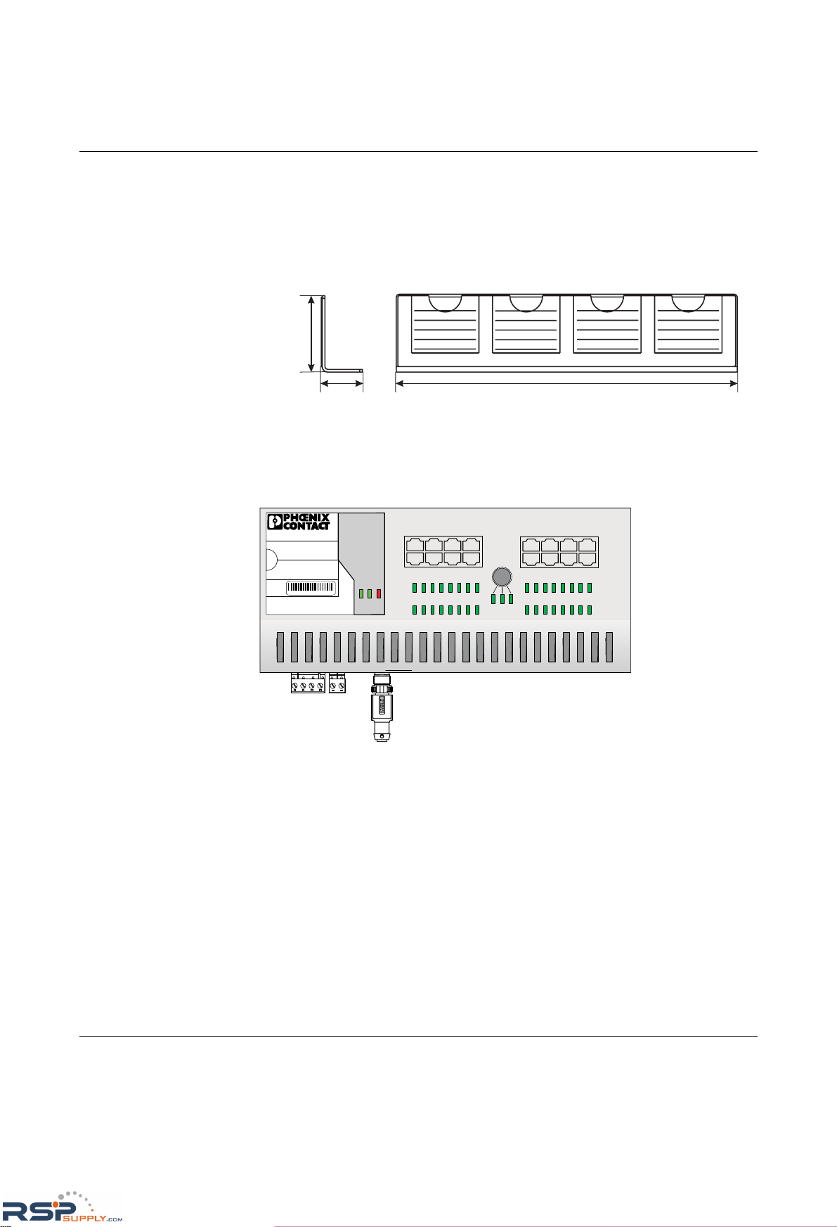
2.5.3 Dimensions of the labeling field
Figure 2-13 Dimensions of the labeling field
2.6 FL MEM PLUG (accessories)
Figure 2-14 Switch with MEM PLUG inserted
As shown in Figure 2-14, insert the FL MEM PLUG memory module in the appropriate M12
female connector on the bottom of the MCS. Once inserted, carefully turn the safety screw
clockwise.
To remove the MEM PLUG, perform the above in reverse order.
The MEM PLUG can be inserted and removed during operation.
125 mm / 4.921 in.
15 mm / 0.591 in.
29 mm /
1.142 in.
FL SWITCH MCS 16TX
Ord. No.28 32 70 0
00.A0.45.1B.D2.1D
MAC
Address
1 3 57
2468
9
11
13
15
10
12
14
16
91610 11 12 13 14 15
1 82 3 4567
MODE
ACT
100
FD
US1US2
FAIL
X19
V.24
X17
US1 GND US2 GND
X18
R1 R2
70563004
RSPSupply - 1-888-532-2706 - www.RSPSupply.com
http://www.RSPSupply.com/p-14178-Phoenix-Contact-2832357-FL-IF-2TX-VS-RJ-D-Media-Module-for-Modular-Switch.aspx
Page 42
FL SWITCH MM HS
2-10
PHOENIX CONTACT 6874_en_16
2.7 Installing the MMS or MCS
2.7.1 Connecting the supply voltage to the MMS/MCS
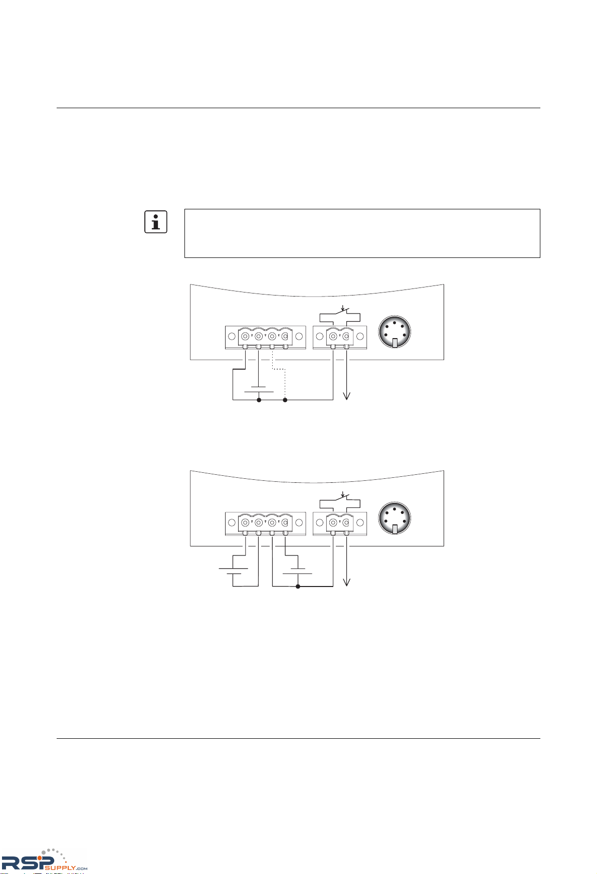
24 V DC The system is operated using a 24 V DC voltage, which is applied at the head station or
MCS. If required, the voltage can also be supplied redundantly (see Figure 2-16).
Figure 2-15 Supplying the system using one voltage source
Redundant 24 V DC supply
Figure 2-16 Supplying the system using two voltage sources
If redundant power supply monitoring is active (default setting), an error is indicated if only
one voltage is applied. A bridge between US1 and US2 (dotted line connection) prevents
this error message. It is also possible to deactivate monitoring in web-based management
or via SNMP.
6 8 7 4 0 0 0 5
U S 2U S 1 G N D G N D R 1 R 2
V . 2 4
2 4 V D C
X 5 X 6 X 7
2 4 V D C
6 8 7 4 0 0 0 6
2 4 V D C
U S 2U S 1 G N D G N D R 1 R 2
V . 2 4
X 5 X 6 X 7
RSPSupply - 1-888-532-2706 - www.RSPSupply.com
http://www.RSPSupply.com/p-14178-Phoenix-Contact-2832357-FL-IF-2TX-VS-RJ-D-Media-Module-for-Modular-Switch.aspx
Page 43
Mounting and installation
6874_en_16 PHOENIX CONTACT 2-11
2.7.2 Connecting the supply voltage to the FL SWITCH MM HS/M
for GL-certified operation
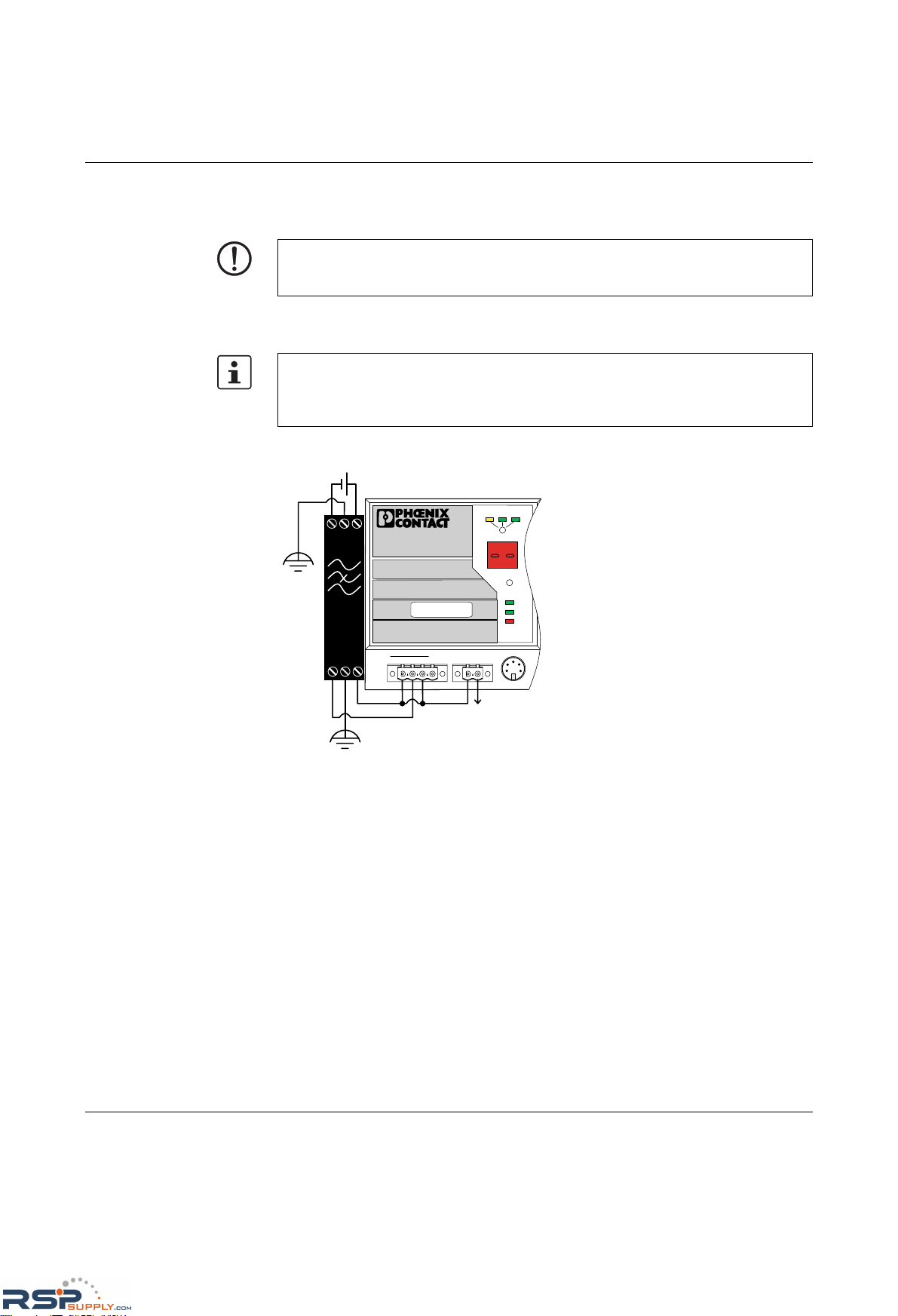
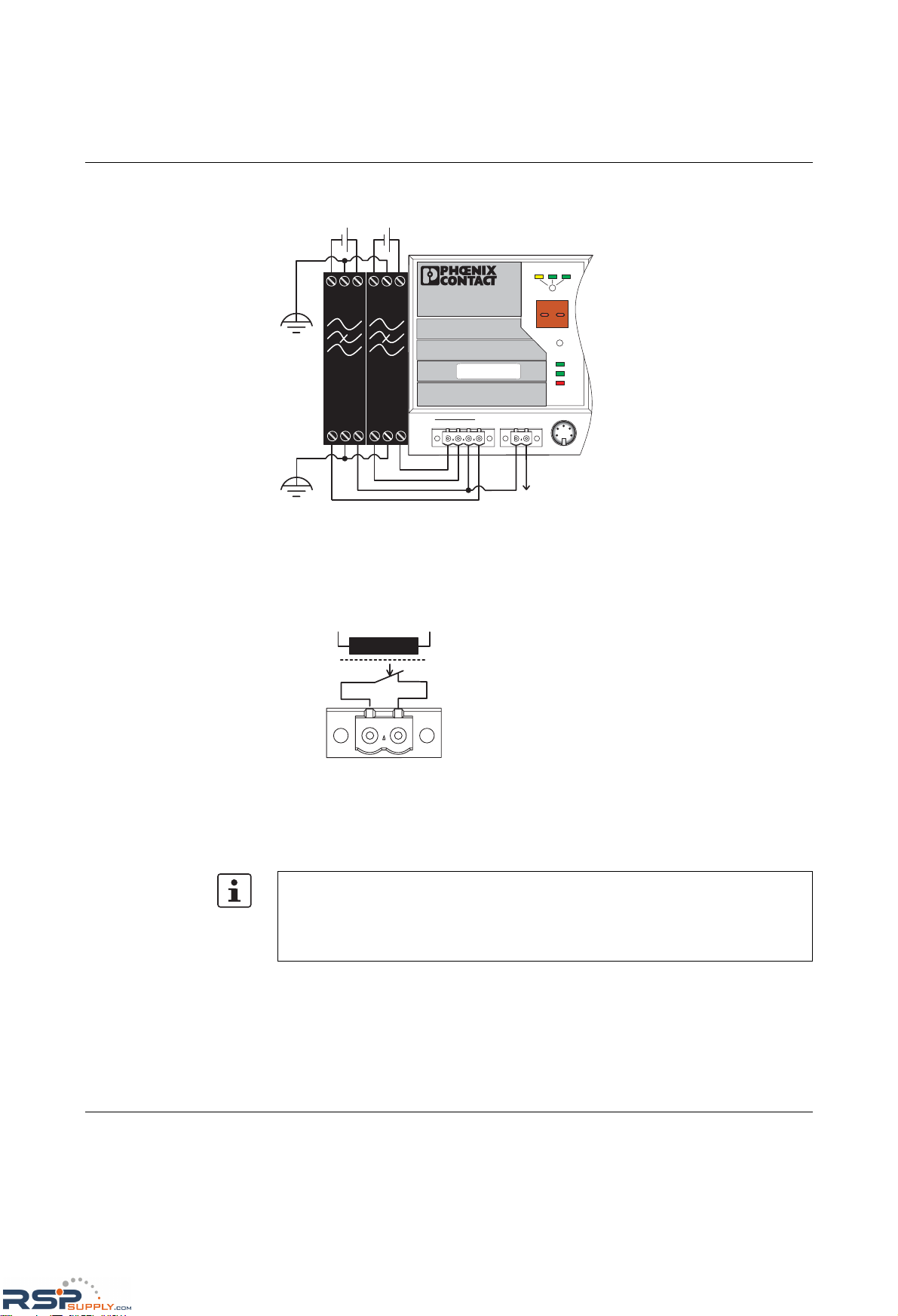
24 V DC The system is operated using a 24 V DC voltage, which is applied at the head station. If
required, the voltage can also be supplied redundantly (see Figure 2-18).
Figure 2-17 Supplying the system using one voltage source
NOTE: For GL-certified operation, an NEF 1- 3 filter (for Environmental Category EMC2)
or NEF 1- 6 (for EMC1) must be used and the components must be installed in a metal
control cabinet.
If redundant power supply monitoring is active (default setting), an error is indicated if only
one voltage is applied. A bridge between US1 and US2 (dotted line connection) prevents
this error message. It is also possible to deactivate monitoring in web-based management
or via SNMP.
US1
US2
Fail
Reset
MODE
ACT
100
FD
FL SWITCH MM HS
Ord. No. 28 32 32 6
US2US1
GND GND
R1 R2
00A0451BDD
MAC
Address
V.24
NEF
1- 3
24VDC
-
+
RSPSupply - 1-888-532-2706 - www.RSPSupply.com
http://www.RSPSupply.com/p-14178-Phoenix-Contact-2832357-FL-IF-2TX-VS-RJ-D-Media-Module-for-Modular-Switch.aspx
Page 44
FL SWITCH MM HS
2-12
PHOENIX CONTACT 6874_en_16
Redundant 24 V DC
supply
Figure 2-18 Supplying the system using two voltage sources
2.7.3 Alarm contact
The switch has a floating alarm contact. An error is indicated when the contact is opened.
Figure 2-19 Basic circuit diagram for the alarm contact
The indicated error states are configured in web-based management or via SNMP. For a list
of error states that can be configured, please refer to Section ""Diagnostics/Alarm Contact"
menu" on page 4-37.
U S 1
U S 2
F a il
R e s e t
M O D E
A C T 1 0 0 F D
F L S W I T C H M M H S
O r d . N o . 2 8 3 2 3 2 6
U S 2U S 1 G N D G N D R 1 R 2
0 0 A 0 4 5 1 B D D
M A C
A d d r e s s
V . 2 4
N E F
1 - 3
2 4 V D C
-
+
N E F
1 - 3
-
+
R 1 R 2
6 7 8 4 0 0 1 5
In the event of non-redundant power supply, the switch indicates a supply voltage failure
by opening the alarm contact. This error message can be prevented by connecting the
supply voltage to both terminals in parallel, as shown in Figure 2-15 or Figure 2-17 (for GL
on the MMS), or by deactivating redundant power supply monitoring in web-based
management.
RSPSupply - 1-888-532-2706 - www.RSPSupply.com
http://www.RSPSupply.com/p-14178-Phoenix-Contact-2832357-FL-IF-2TX-VS-RJ-D-Media-Module-for-Modular-Switch.aspx
Page 45
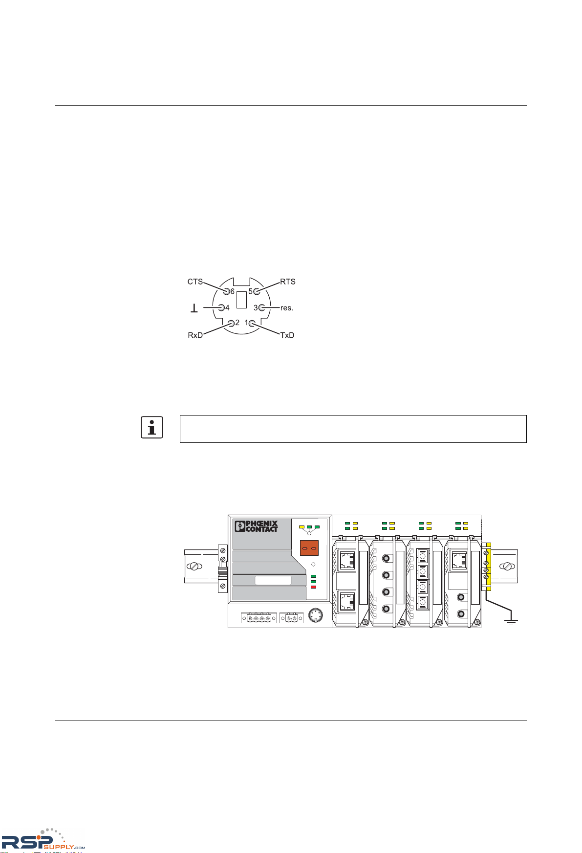
Mounting and installation
6874_en_16 PHOENIX CONTACT 2-13
2.7.4 V.24 (RS-232) interface for external management
The 6-pos. Mini-DIN female connector provides a serial interface to connect a local
management station. It can be used to connect a VT100 terminal or a PC with
corresponding terminal emulation to the management interface (for an appropriate cable,
please refer to page 12-9). Set the following transmission parameters:
Bits per second 38400
Data bits 8
Parity None
Stop bits 1
Flow control None
Figure 2-20 Assignment of the V.24 (RS-232) interface
2.8 Grounding
All Factory Line devices must be grounded so that any possible interference is shielded
from the data telegram and discharged to ground potential.
A wire of at least 2.5 mm
2
must be used for grounding. When mounting on a DIN rail, the DIN
rail must be connected with protective earth ground using grounding terminal blocks. The
module is connected to protective earth ground via the metal base element.
Figure 2-21 Switch on a grounded DIN rail
V.24 (RS-232)
Grounding protects people and machines against hazardous voltages. To avoid these
dangers, correct installation, taking the local conditions into account, is vital.
6 8 7 4 0 0 0 8
L N K M O D E
1
2
X 1
L N K M O D E
1
2
X 2
L N K M O D E
1
2
X 3
L N K M O D E
1
2
X 4
U S 1
U S 2
F a i l
R e s e t
M O D E
A C T 1 0 0 F D
F L S W I T C H M M H S
O r d . N o . 2 8 3 2 3 2 6
U S 2U S 1 G N D G N D R 1 R 2
0 0 A 0 4 5 1 B D D
M A C
A d d r e s s
V .2 4
RSPSupply - 1-888-532-2706 - www.RSPSupply.com
http://www.RSPSupply.com/p-14178-Phoenix-Contact-2832357-FL-IF-2TX-VS-RJ-D-Media-Module-for-Modular-Switch.aspx
Page 46

FL SWITCH MM HS
2-14
PHOENIX CONTACT 6874_en_16
RSPSupply - 1-888-532-2706 - www.RSPSupply.com
http://www.RSPSupply.com/p-14178-Phoenix-Contact-2832357-FL-IF-2TX-VS-RJ-D-Media-Module-for-Modular-Switch.aspx
Page 47
Startup and functions
6874_en_16 PHOENIX CONTACT 3-1
3 Startup and functions
3.1 Basic settings
3.1.1 Default upon delivery/default settings
By default upon delivery or after the system is reset to the default settings, the following
functions and properties are available:
– The password is "private".
– All IP parameters are deleted. The switch has no valid IP parameters:
IP address: 0.0.0.0
Subnet mask: 0.0.0.0
Gateway: 0.0.0.0
– BootP is activated as the addressing mechanism.
– All available ports are activated with the following parameters:
- Auto negotiation
- 100 Mbps - full duplex for FX glass fiber modules and HCS ports
– All counters of the SNMP agent are deleted.
– The web and Telnet server, SNMP agent, and V.24 (RS-232) interface are active.
– Port mirroring, Rapid Spanning Tree, MRP, access control for web interface, port
security, multicast filtering, VLAN, DHCP relay agent option 82, and LLDP are
deactivated.
– Port security is deactivated for all ports.
– Access control for WBM is deactivated.
– The alarm contact only opens in the event of non-redundant power supply and a
detected PoE error.
– The transmission of SNMP traps is deactivated and the switch has no valid trap
destination IP address.
– The aging time is set to 40 seconds.
– The switch is in "Ethernet" mode (default settings).
– The WBM refresh interval is set to 30 seconds.
– Management is in VLAN 1.
– The SNTP function (automatic setting of the system time) is deactivated.
– PROFINET and Ethernet/IP are deactivated.
The basic Ethernet functions do not have to be configured and are available when the
supply voltage is switched on.
The aging time is set using the "dot1dTpAgingTime" MIB object
(OID 1.3.6.1.2.1.17.4.2). The available setting range is 10 - 825 seconds. For static
configuration, an aging time of 300 seconds is recommended.
During switch restart, the active configuration including IP parameters is written to a
plugged-in memory module or MEM plug.
RSPSupply - 1-888-532-2706 - www.RSPSupply.com
http://www.RSPSupply.com/p-14178-Phoenix-Contact-2832357-FL-IF-2TX-VS-RJ-D-Media-Module-for-Modular-Switch.aspx
Page 48
Product designation
3-2
PHOENIX CONTACT 6874_en_16
3.2 Using Smart mode
Smart mode enables the user to change the operating mode of the switch without having to
access the management interface.
The switch offers the following setting options via Smart mode:
– Reset to default settings
– Set PROFINET mode
– Set Ethernet/IP mode
– Exit Smart mode without changes
3.2.1 Activating Smart mode
The mode button is used to call/exit Smart mode and to select the desired setting. The three
mo de L EDs indicate the mode tha t is cur rently set and the mode that is entered when exiting
Smart mode.
3.2.1.1 Calling Smart mode
• Once the switch has booted, as soon as the three mode LEDs go out press and hold
down the mode button for at least five seconds. When Smart mode is active, the three
LEDs flash.
• When Smart mode is started, the switch is initially in the "Exit without changes" state.
3.2.1.2 Selecting the desired setting
• To select the various settings, press the mode button briefly and select the desired
operating mode.
3.2.1.3 Exiting Smart mode
• To exit, press and hold down the mode button for at least five seconds. The previously
selected operating mode is saved.
3.2.1.4 Possible operating modes in Smart mode
The switch supports the selection of the following operating modes in Smart mode (see also
example below):
Table 3-1 Operating modes in Smart mode
Mode ACT
LED 1
100
LED 2
FD
LED 3
Display (MMS only)
Exit Smart mode without changes OFF OFF ON S1
Reset to default settings OFF ON OFF S2
Set PROFINET mode OFF ON ON S3
Set Ethernet/IP mode ON OFF OFF S4
RSPSupply - 1-888-532-2706 - www.RSPSupply.com
http://www.RSPSupply.com/p-14178-Phoenix-Contact-2832357-FL-IF-2TX-VS-RJ-D-Media-Module-for-Modular-Switch.aspx
Page 49
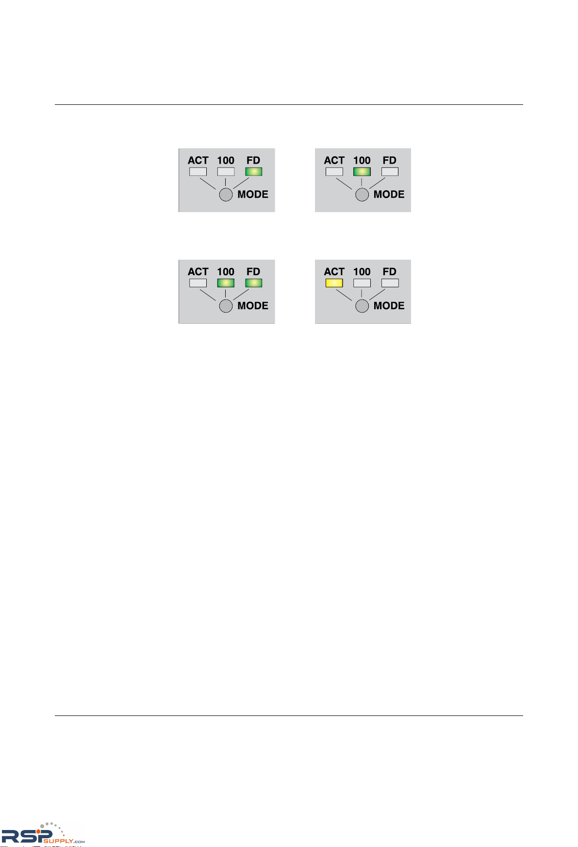
Startup and functions
6874_en_16 PHOENIX CONTACT 3-3
Example:
When the switch is in Smart mode, exiting Smart mode triggers the following action:
Figure 3-1 Example for Smart mode
Exit without
changes
PROFINET Ethernet/IP
687412081
Reset to default
settings
RSPSupply - 1-888-532-2706 - www.RSPSupply.com
http://www.RSPSupply.com/p-14178-Phoenix-Contact-2832357-FL-IF-2TX-VS-RJ-D-Media-Module-for-Modular-Switch.aspx
Page 50
Product designation
3-4
PHOENIX CONTACT 6874_en_16
3.2.2 Assigning IP parameters
When the supply voltage is switched on or the reset button is pressed, the switch sends
requests (BootP requests) to assign IP parameters.
The assignment of valid IP parameters is vital to the management function of the switch.
Options for assigning IP parameters:
– Configuration via the BootP protocol (default upon delivery)
– Static configuration via the management interfaces
– DHCP (Dynamic Host Configuration Protocol)
– DCP (Discovery and Configuration Protocol)
3.2.2.1 Valid IP parameters
IP parameters comprise the following three elements: "IP address", "subnet mask", and
"default gateway/router".
Valid IP addresses are:
000.000.000.001 to 126.255.255.255
128.000.000.000 to 223.255.255.255
Valid multicast addresses are:
224.000.000.001 to 239.255.255.255
Valid subnet masks are:
255.000.000.000 to 255.255.255.252
Default gateway/router:
The IP address of the gateway/router must be in the same subnetwork as the address of the
switch.
3.2.2.2 Assigning IP addresses
The IP address is a 32-bit address, which consists of a network part and a user part. The
network part consists of the network class and the network address.
There are currently five defined network classes; Classes A, B, and C are used in modern
applications, while Classes D and E are hardly ever used. It is therefore usually sufficient if
a network device only "recognizes" Classes A, B, and C.
Figure 3-2 Position of bits within the IP address
The button must be held down for a few seconds to trigger a reset.
The "BootP" function can be deactivated via the management. By default upon delivery,
the "BootP" function is activated.
If the switch has not received any valid IP parameters, "01" or "dc" appears in the display
and one of the mode LEDs (ACT, 100 or FD) flashes.
Section 4.1.2 on page 4-1 describes the assignment of IP parameters with Factory
Manager 2.1.
Bit 1
Bit 32
61462056
RSPSupply - 1-888-532-2706 - www.RSPSupply.com
http://www.RSPSupply.com/p-14178-Phoenix-Contact-2832357-FL-IF-2TX-VS-RJ-D-Media-Module-for-Modular-Switch.aspx
Page 51
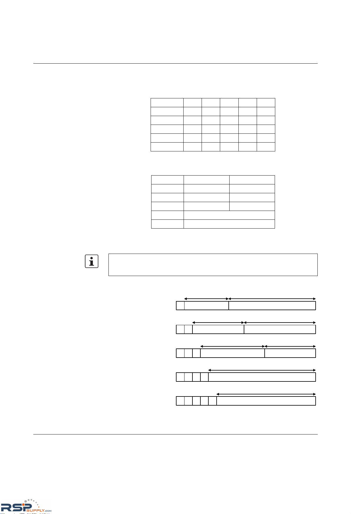
Startup and functions
6874_en_16 PHOENIX CONTACT 3-5
With binary representation of the IP address, the network class is represented by the first
bits. The key factor is the number of "ones" before the first "zero". The assignment of
classes is shown in the following table. The empty cells in the table are not relevant to the
network class and are already used for the network address.
The bits for the network class are followed by those for the network address and the user
address. Depending on the network class, a different number of bits are available, both for
the network address (network ID) and the user address (host ID).
IP addresses can be represented in decimal or hexadecimal form. In decimal notation,
bytes are separated by dots (dotted decimal notation) to show the logical grouping of the
individual bytes.
Possible address combinations
Figure 3-3 Structure of IP addresses
Bit 1 Bit 2 Bit 3 Bit 4 Bit 5
Class A 0
Class B 10
Class C 110
Class D 1110
Class E 11110
Network ID Host ID
Class A 7 bits 24 bits
Class B 14 bits 16 bits
Class C 21 bits 8 bits
Class D 28-bit multicast identifier
Class E 27 bits (reserved)
The decimal points do not divide the address into a network and user address. Only the
value of the first bits (before the first "zero") specifies the network class and thus the
number of remaining bits in the address.
7 bits
24 bits
14 bits 16 bits
21 bits
8 bits
28 bits
27 bits
Network ID
Host ID
Host ID
Host ID
Identifier for multicast group
Reserved for future applications
0
0
0
0
0
1
11
11
1
1111
Class A
0.0.0.0 - 127.255.255.255
Class B
128.0.0.0 - 191.255.255.255
Class C
192.0.0.0 - 223.255.255.255
Class D
224.0.0.0 - 239.255.255.255
Class E
240.0.0.0 - 247.255.255.255
61492009
Network ID
Network ID
RSPSupply - 1-888-532-2706 - www.RSPSupply.com
http://www.RSPSupply.com/p-14178-Phoenix-Contact-2832357-FL-IF-2TX-VS-RJ-D-Media-Module-for-Modular-Switch.aspx
Page 52

Product designation
3-6
PHOENIX CONTACT 6874_en_16
3.2.2.3 Special IP addresses for special applications
Certain IP addresses are reserved for special functions. The following addresses should not
be used as standard IP addresses.
127.x.x.x addresses
The Class A network address "127" is reserved for a loopback function on all computers,
regardless of the network class. This loopback function may only be used on networked
computers for internal test purposes.
If a telegram is addressed to a computer with the value 127 in the first byte, the receiver
immediately sends the telegram back to the transmitter.
Correct installation and configuration of the TCP/IP software, for example, can be checked
in this way.
As Layers 1 and 2 of the ISO/OSI reference model are not included in the test they should
be tested separately using the ping function.
Value 255 in the byte
Value 255 is defined as a broadcast address. The telegram is sent to all the computers that
are in the same part of the network. Examples: 004.255.255.255, 198.2.7.255 or
255.255.255.255 (all the computers in all the networks). If the network is divided into
subnetworks, the subnet masks must be observed during calculation, otherwise some
devices may be omitted. Simplified: The last address of an area is reserved as the
broadcast address.
0.x.x.x addresses
Value 0 is the ID of the specific network. If the IP address starts with a zero, the receiver is
in the same network. Example: 0.2.1.1 refers to device 2.1.1 in this network.
The zero previously signified the broadcast address. If older devices are used,
unauthorized broadcast and complete overload of the entire network (broadcast storm) may
occur when using the IP address 0.x.x.x.
3.2.2.4 Subnet masks
Routers and gateways divide large networks into several subnetworks. The IP addresses
for individual devices are assigned to specific subnetworks by the subnet mask. The
network part of an IP address is not modified by the subnet mask. An extended IP address
is generated from the user address and subnet mask. Because the masked subnetwork is
only recognized by the local computers, this extended IP address appears as a standard IP
address to all the other devices.
Structure of the subnet mask
The subnet mask always contains the same number of bits as an IP address. The subnet
mask has the same number of bits (in the same position) set to "one", which is reflected in
the IP address for the network class.
Example: An IP address from Class A contains a 1-byte network address and a 3-byte
computer address. Therefore, the first byte of the subnet mask may only contain "ones".
RSPSupply - 1-888-532-2706 - www.RSPSupply.com
http://www.RSPSupply.com/p-14178-Phoenix-Contact-2832357-FL-IF-2TX-VS-RJ-D-Media-Module-for-Modular-Switch.aspx
Page 53

Startup and functions
6874_en_16 PHOENIX CONTACT 3-7
The remaining bits (three bytes) then contain the address of the subnetwork and the
computer. The extended IP address is created when the bits of the IP address and the bits
of the subnet mask are ANDed. Because the subnetwork is only recognized by local
devices, the corresponding IP address appears as a "normal" IP address to all the other
devices.
Application
If the ANDing of the address bits gives the local network address and the local subnetwork
address, the device is located in the local network. If the ANDing gives a different result, the
data telegram is sent to the subnetwork router.
Example for a Class B subnet mask:
Using this subnet mask, the TCP/IP protocol software differentiates between the devices
that are connected to the local subnetwork and the devices that are located in other
subnetworks.
Example: Device 1 wants to establish a connection with device 2 using the above subnet
mask. Device 2 has IP address 59.EA.55.32.
IP address representation for device 2:
The individual subnet mask and the IP address for device 2 are then ANDed bit-by-bit by the
software to determine whether device 2 is located in the local subnetwork.
ANDing the subnet mask and IP address for device 2:
After ANDing, the software determines that the relevant subnetwork (01) does not
correspond to the local subnetwork (11) and the data telegram is forwarded to a subnetwork
router.
255.255.192.0
1111 1111.1111 1111.1100 0000.0000 0000
Decimal representation:
Binary representation:
Subnet mask bits
Class B
61462010
59.EA.55.32
0101 1001.1110 1010.0101 0101.0011 0010
Hexadecimal representation:
Decimal representation:
61462011
1111 1111.1111 1111.1100 0000.0000 0000
0101 1001.1110 1010.0101 0101.0011 0010
0101 1001.1110 1010.0100 0000.0000 0000
Subnet mask:
IP address:
Result:
AND
Subnetwork
61462012
RSPSupply - 1-888-532-2706 - www.RSPSupply.com
http://www.RSPSupply.com/p-14178-Phoenix-Contact-2832357-FL-IF-2TX-VS-RJ-D-Media-Module-for-Modular-Switch.aspx
Page 54
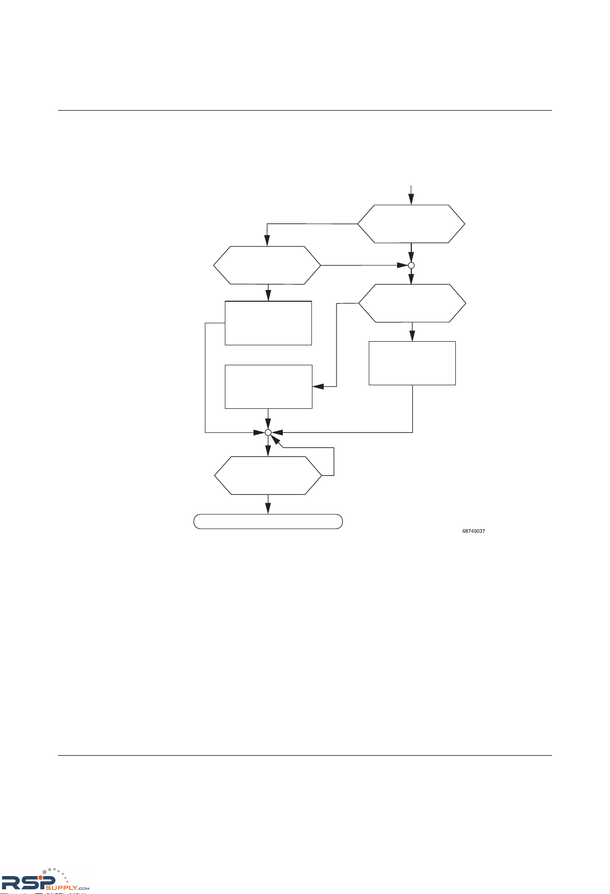
Product designation
3-8
PHOENIX CONTACT 6874_en_16
3.2.3 Flowchart after a restart
3.2.3.1 Loading the configuration data
Figure 3-4 Flowchart: Loading the configuration data
System start
Yes
Memory module
inserted?
No
Data in memory
module valid?
No
Yes
Load data from
memory module
Load data from
head station Flash
Data in head
station Flash valid?
No
Load default values
No
Boot process
completed?
Save data
Yes
RSPSupply - 1-888-532-2706 - www.RSPSupply.com
http://www.RSPSupply.com/p-14178-Phoenix-Contact-2832357-FL-IF-2TX-VS-RJ-D-Media-Module-for-Modular-Switch.aspx
Page 55
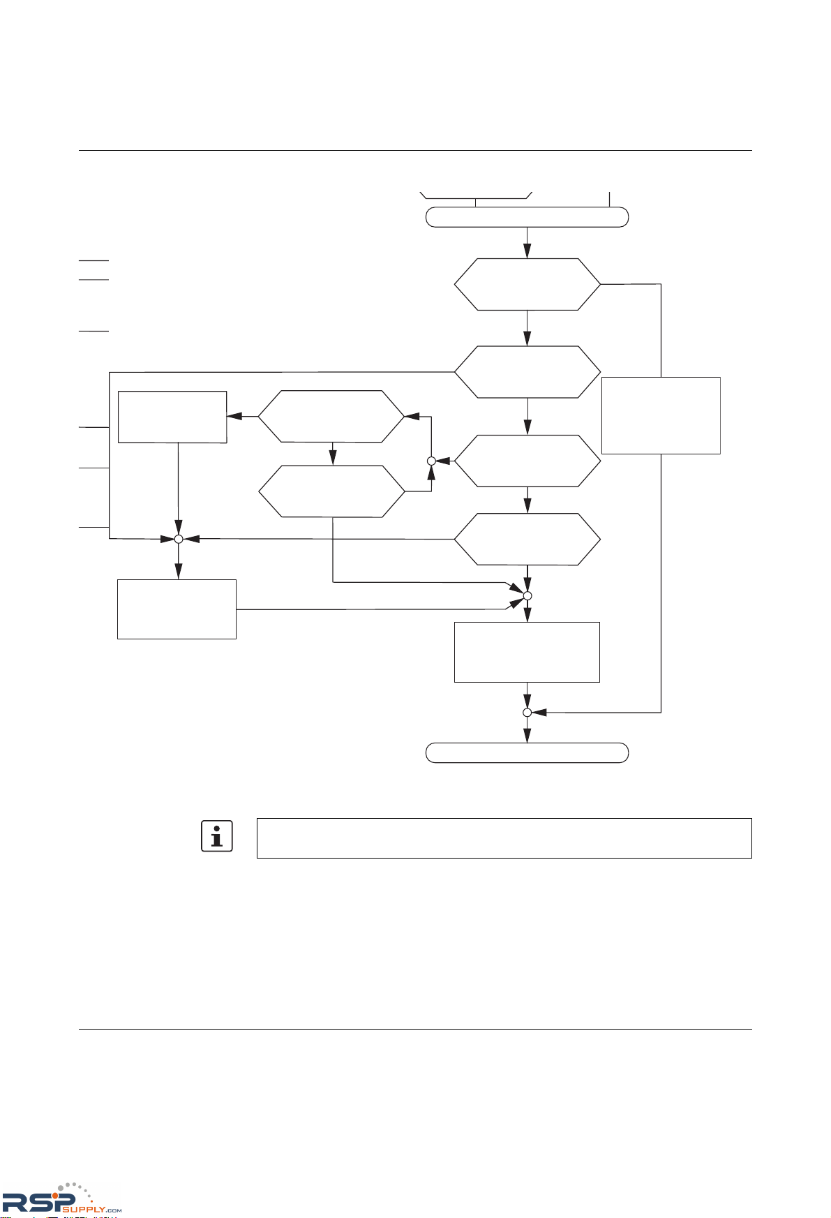
Startup and functions
6874_en_16 PHOENIX CONTACT 3-9
3.2.3.2 Assigning IP parameters
Figure 3-5 Flowchart: Assigning IP parameters
009
Assignment of static
IP parameters via
V.24 (RS-232)?
No
Assignment of
IP parameters
via BootP?
Yes
No
Assignment of
IP parameters
via DHCP?
No
Yes*
IP parameters
received from
BootP server
Entry of
IP parameters
local configuration
Yes
*
If the DHCP server
does not respond,
indefinite waiting time
No
Three requests
remain unanswered?
Yes
Yes
Is there a valid
local IP address?
No
Start with local
configuration data,
as long as valid data
is available
Startup completed
No
Device is started
up by the PROFINET IO
controller or
an engineering tool
Startup
687407009
Assignment of static
IP parameters via
V.24 (RS-232)?
No
Assignment of
IP parameters
via BootP?
Yes
No
Assignment of
IP parameters
via DHCP?
No
Yes*
IP parameters
received from
BootP server
Entry of
IP parameters
as local configuration
Yes
*
If the DHCP server
does not respond,
indefinite waiting time
No
Three requests
remain unanswered?
Yes
Yes
Is there a valid
local IP address?
No
Start with local
configuration data,
as long as valid data
is available
Startup completed
Operating as
a PROFINET
device with DCP?
No
Yes
Device is started
up by the PROFINET IO
controller or
an engineering tool
If DHCP is selected as the assignment mechanism, the DHCP server must offer a DHCP
lease time of at least five minutes, so that the switch accepts the assigned IP parameters.
RSPSupply - 1-888-532-2706 - www.RSPSupply.com
http://www.RSPSupply.com/p-14178-Phoenix-Contact-2832357-FL-IF-2TX-VS-RJ-D-Media-Module-for-Modular-Switch.aspx
Page 56
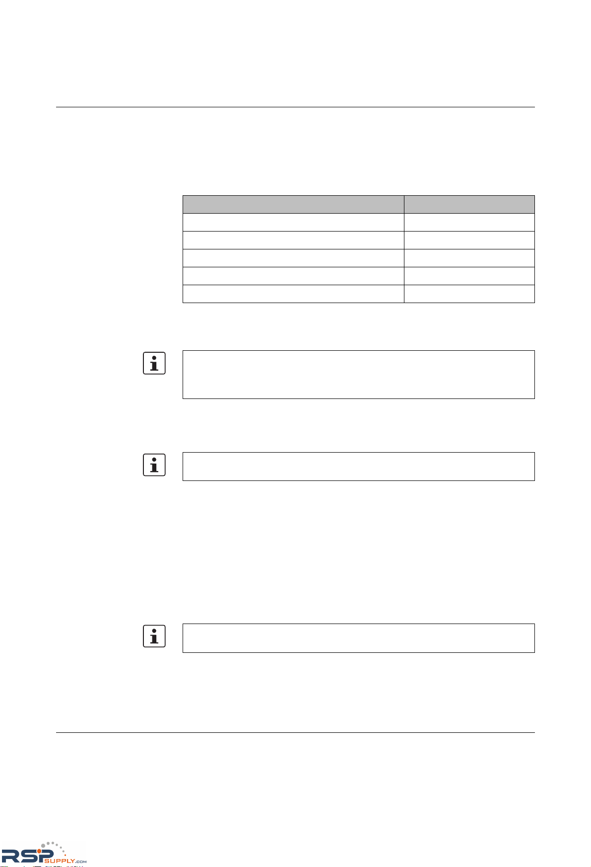
Product designation
3-10
PHOENIX CONTACT 6874_en_16
3.3 Starting up interface modules with the MMS
For GL-certified operation, only the interface modules listed in the table below are
permitted.
3.3.1 FL IF 2TX VS-RJ ...
3.3.1.1 Default upon delivery
When the interface modules are inserted, the auto negotiation and auto crossing functions
are activated. Link monitoring for the twisted pair ports is not activated.
3.3.1.2 Functions
–Auto negotiation
Auto negotiation is a method whereby the switch automatically detects the operating
parameters for the connected network and sets the corresponding parameters
(10 Mbps or 100 Mbps data transmission rate and half or full duplex transmission
mode) for its RJ45 ports. Automatic port setting eliminates the need for manual
intervention by the user. The auto negotiation function can be activated/deactivated via
the web interface.
– Auto crossing
There is no need to distinguish between 1:1 and crossover cables, as the transmit and
receive cables are crossed automatically.
– Auto polarity
The polarity is changed automatically by the switch if a pair of twisted pair receive
cables (RD+ and RD-) are connected incorrectly.
Table 3-2 Interface modules with GL approval
Designation Order No.
FL IF MEM 2TX-D 2832483
FL IF 2FX SC-D 2832425
FL IF 2FX SM SC-D 2832205
FL IF 2TX VS-RJ-F 2832344
FL IF 2TX VS-RJ-D 2832357
Hot plugging
When inserting and removing interface modules, you do not have to switch off the supply
voltage. The interface modules are detected automatically and logged to the network
management.
If an interface module is inserted in a MMS that has already been parameterized, the
existing configuration remains active.
Auto crossing is only available if auto negotiation is activated.
RSPSupply - 1-888-532-2706 - www.RSPSupply.com
http://www.RSPSupply.com/p-14178-Phoenix-Contact-2832357-FL-IF-2TX-VS-RJ-D-Media-Module-for-Modular-Switch.aspx
Page 57
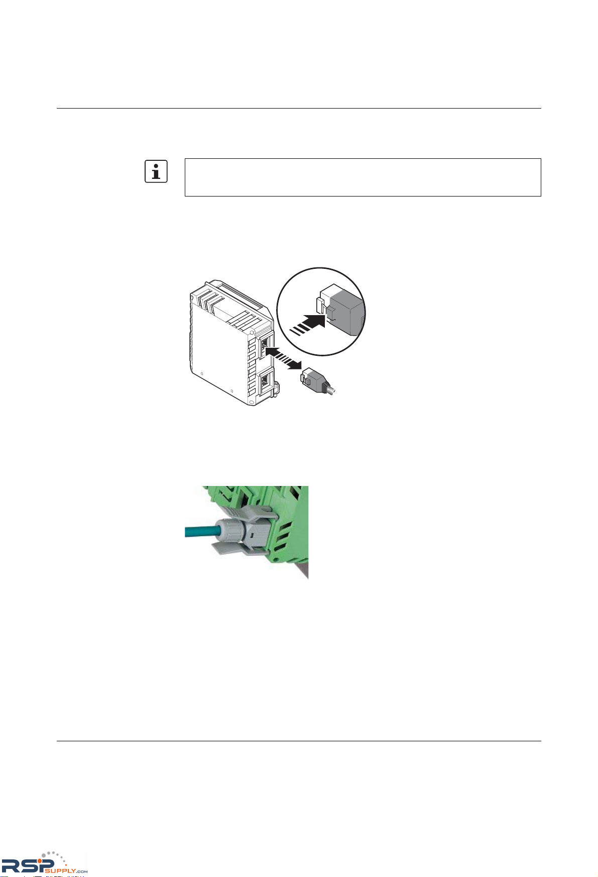
Startup and functions
6874_en_16 PHOENIX CONTACT 3-11
–Line monitoring
The switch uses link test pulses according to standard IEEE 802.3 at regular intervals
to monitor the connected TP/TX cable segments for short circuits and interrupts.
3.3.1.3 Connecting the RJ45 connectors
Insert the RJ45 male connector into the female connector according to the keying until it
snaps into place. To remove the connector, press the snap-in device in the direction of the
connector (A) and then remove the connector.
Figure 3-6 Connecting the RJ45 connectors
Industrial RJ45 connector with additional latching
The figure below shows the VS-08-T-G-RJ45/IP20, which can be snapped directly onto the
interface module.
Figure 3-7 Using the VS-08-T-G-RJ45/IP20
Ports that are not being used are considered cable interrupts. In addition, a TP/TX path to
a deactivated termination device is also considered a cable interrupt, as the connected
device cannot send a link test pulse because it is switched off.
i
g
i
t
a
l
I
n
p
1
i
g
i
t
a
l
I
n
p
1
6 8 7 4 0 0 1 6
A
RSPSupply - 1-888-532-2706 - www.RSPSupply.com
http://www.RSPSupply.com/p-14178-Phoenix-Contact-2832357-FL-IF-2TX-VS-RJ-D-Media-Module-for-Modular-Switch.aspx
Page 58
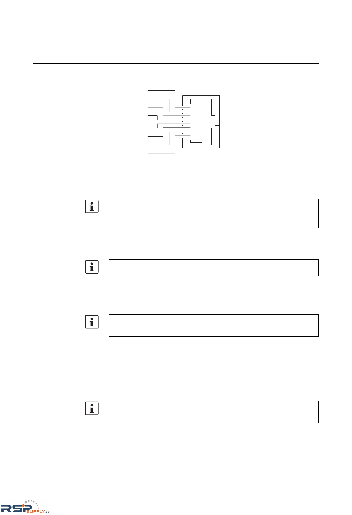
Product designation
3-12
PHOENIX CONTACT 6874_en_16
3.3.1.4 Assignment of the RJ45 female connector (TP/TX)
Figure 3-8 Assignment of the RJ45 female connector
3.3.2 FL IF 2POF 10/100 ...
3.3.2.1 Default upon delivery
When the interface modules are inserted, the auto negotiation function is activated, but link
monitoring for the POF ports is not activated.
3.3.2.2 Functions
–Line monitoring
According to standard IEEE 802.3, the switch monitors the connected fiber optic cables
for interrupts.
–Auto negotiation
Auto negotiation is a method whereby the switch automatically detects the operating
parameters for the connected network and sets the corresponding parameters
(10 Mbps/100 Mbps data transmission rate and half/full duplex transmission mode) for
its F-SMA ports. Automatic port setting eliminates the need for manual intervention by
the user. The auto negotiation function can be activated/deactivated via the web
interface.
3.3.2.3 Connecting the F-SMA connectors
P i n 1
P i n 2
P i n 3
P i n 4
P i n 5
P i n 6
P i n 7
P i n 8
R D
+
R D
-
T D
+
T D
-
n . c .
n . c .
n . c .
n . c .
R J 4 5
Hot plugging
When inserting and removing interface modules, you do not have to switch off the supply
voltage. The interface modules are detected automatically and logged to the network
management.
If an interface module is inserted in a MMS that has already been parameterized, the
existing configuration remains active.
Ports that are not being used are considered cable interrupts. In addition, a POF path to a
deactivated termination device is also considered a cable interrupt, as the connected
device cannot send a link test pulse because it is switched off.
To prevent dirt from entering the connectors, do not remove the dust protection caps until
just before connecting the connectors. The same applies for the protective caps on the
connectors.
RSPSupply - 1-888-532-2706 - www.RSPSupply.com
http://www.RSPSupply.com/p-14178-Phoenix-Contact-2832357-FL-IF-2TX-VS-RJ-D-Media-Module-for-Modular-Switch.aspx
Page 59
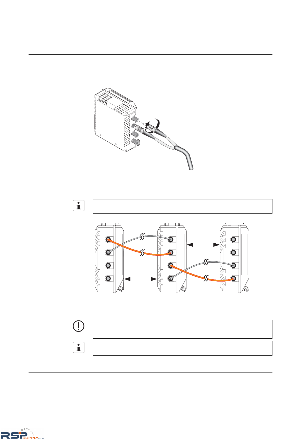
Startup and functions
6874_en_16 PHOENIX CONTACT 3-13
F-SMA is a standardized fiber optic connection. We recommend the use of easy to operate
F-SMA connectors with quick mounting connection from Phoenix Contact.
The connectors are secured on the interface module by manually tightening the screw
collar.
Figure 3-9 Connecting the F-SMA connectors
3.3.2.4 POF connection between devices
Figure 3-10 POF connection
3.3.2.5 Reducing the transmission power
6 8 7 4 0 0 1 7
When connecting two POF interface modules, note the signal direction of the fiber optics.
The fiber connection is always from the transmitter to the receiver.
6 8 7 4 0 0 1 8
M a x . 5 0 m
P O F
M a x . 5 0 m
P O F
R X
R X
T X
T X
R X
R X
T X
T X
R X
R X
T X
T X
NOTE: In polymer fiber optic paths (POF) < 20 m, the transmission power must be
reduced. Slide the switch on the top of the interface module to the "OFF" position. Note the
assignment of port numbers.
The switch position can be read in WBM or via SNMP.
RSPSupply - 1-888-532-2706 - www.RSPSupply.com
http://www.RSPSupply.com/p-14178-Phoenix-Contact-2832357-FL-IF-2TX-VS-RJ-D-Media-Module-for-Modular-Switch.aspx
Page 60
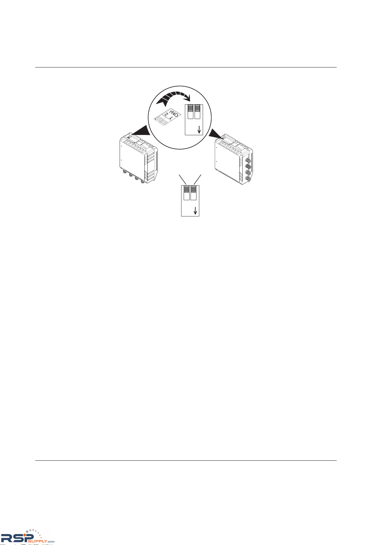
Product designation
3-14
PHOENIX CONTACT 6874_en_16
Figure 3-11 Assignment of F-SMA ports to the DIP switch
1
2
O N
6 8 7 4 0 0 1 9
1 2
O N
1
2
O N
P o r t
1
P o r t
2
P o r t
1
P o r t
1
P o r t
2
P o r t
2
1 2
O N
RSPSupply - 1-888-532-2706 - www.RSPSupply.com
http://www.RSPSupply.com/p-14178-Phoenix-Contact-2832357-FL-IF-2TX-VS-RJ-D-Media-Module-for-Modular-Switch.aspx
Page 61
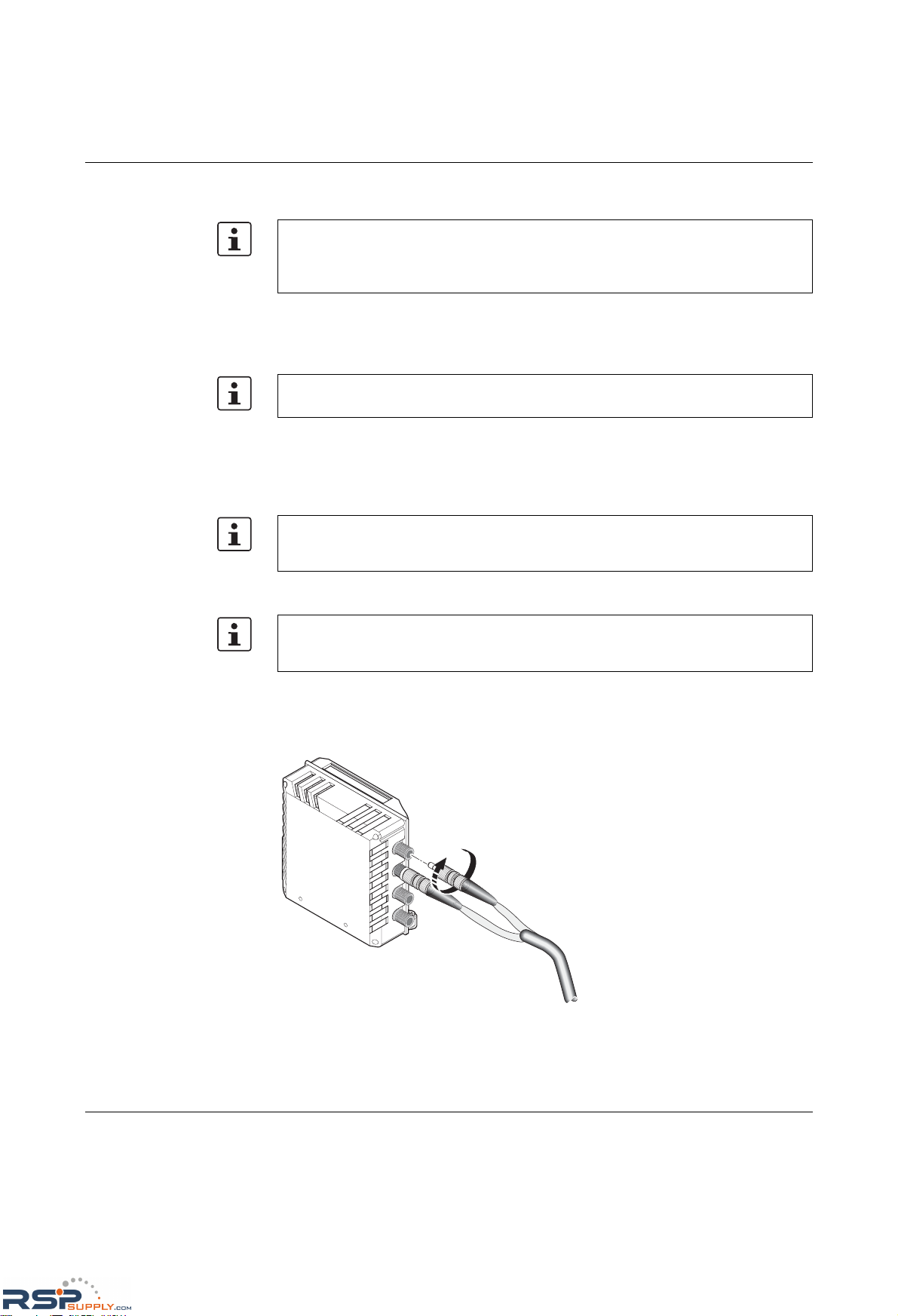
Startup and functions
6874_en_16 PHOENIX CONTACT 3-15
3.3.3 FL IF 2HCS 100 ...
3.3.3.1 Default upon delivery
When the interface modules are inserted, the link monitoring function for the HCS ports is
not activated.
3.3.3.2 Functions
–Line monitoring
According to standard IEEE 802.3, the switch monitors the connected fiber optic cables
for interrupts.
3.3.3.3 Connecting the F-SMA connectors
F-SMA is a standardized fiber optic connection. We recommend the use of easy to operate
F-SMA connectors with quick mounting connection from Phoenix Contact.
The connectors are secured on the interface module by manually tightening the screw
collar.
Figure 3-12 Connecting the F-SMA connectors
Hot plugging
When inserting and removing interface modules, you do not have to switch off the supply
voltage. The interface modules are detected automatically and logged to the network
management.
An HCS port is set to 100 Mbps - full duplex. If an HCS port is removed, the port mode is
set to auto negotiation.
Ports that are not being used are considered cable interrupts. In addition, an HCS path to
a deactivated termination device is also considered a cable interrupt, as the connected
device cannot send a link test pulse because it is switched off.
To prevent dirt from entering the connectors, do not remove the dust protection caps until
just before connecting the connectors. The same applies for the protective caps on the
connectors.
6 8 7 4 0 0 1 7
RSPSupply - 1-888-532-2706 - www.RSPSupply.com
http://www.RSPSupply.com/p-14178-Phoenix-Contact-2832357-FL-IF-2TX-VS-RJ-D-Media-Module-for-Modular-Switch.aspx
Page 62
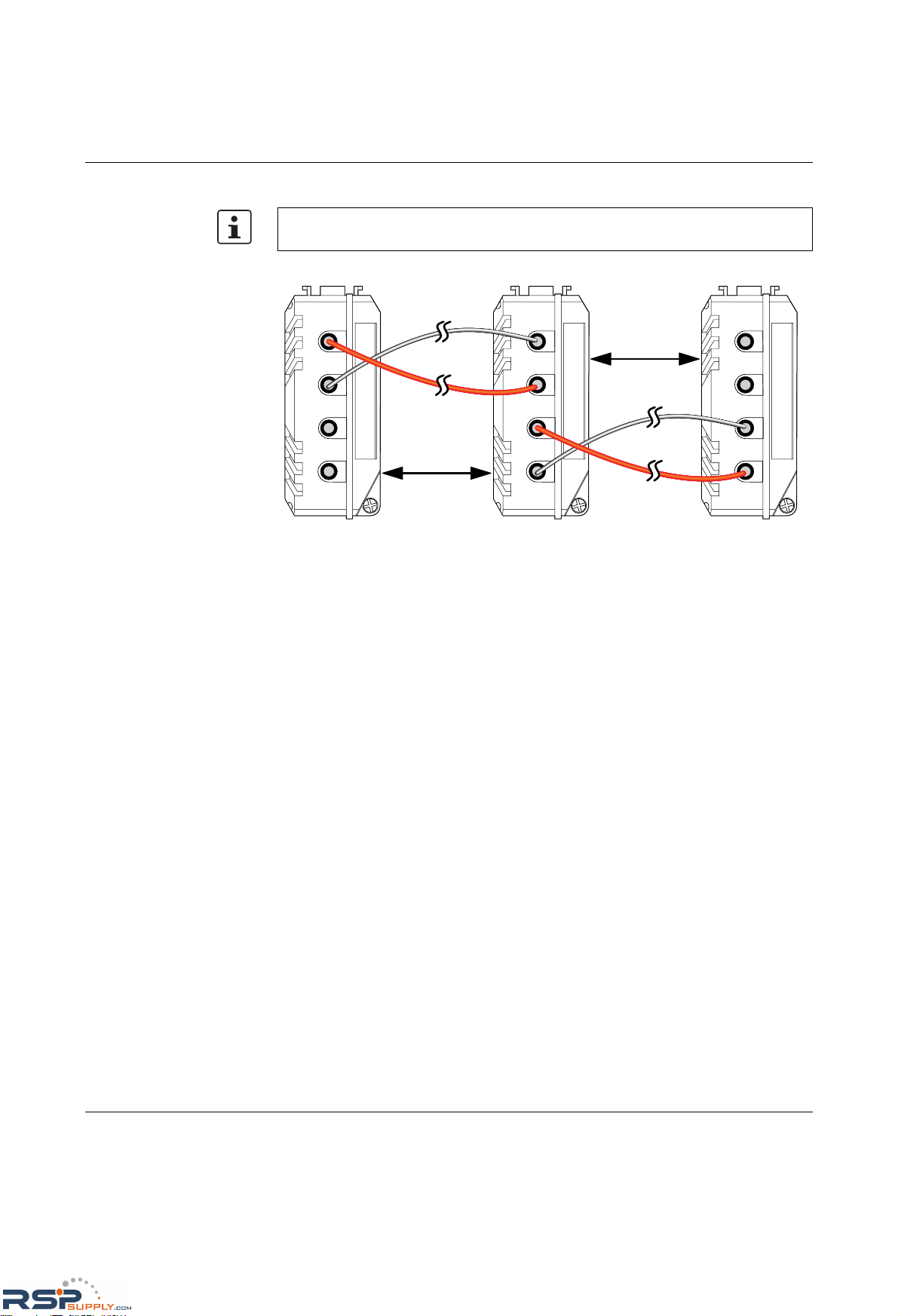
Product designation
3-16
PHOENIX CONTACT 6874_en_16
3.3.3.4 HCS connection between devices
Figure 3-13 HCS connection
When connecting two HCS interface modules, note the signal direction of the fiber optics.
The fiber connection is always from the transmitter to the receiver.
68740046
Max. 100 m
HCS
Max. 100 m
HCS
RX
RX
TX
TX
RX
RX
TX
TX
RX
RX
TX
TX
RSPSupply - 1-888-532-2706 - www.RSPSupply.com
http://www.RSPSupply.com/p-14178-Phoenix-Contact-2832357-FL-IF-2TX-VS-RJ-D-Media-Module-for-Modular-Switch.aspx
Page 63
Startup and functions
6874_en_16 PHOENIX CONTACT 3-17
3.3.4 FL IF 2FX SC .../FL IF 2FX SM SC ...
3.3.4.1 Default upon delivery
When the interface modules are inserted, they are preset with a data transmission rate of
100 Mbps and full duplex mode, and link monitoring is not activated for the fiber optic ports.
3.3.4.2 Functions
–Line monitoring
According to standard IEEE 802.3, the switch monitors the connected fiber optic cables
for interrupts.
– Far End Fault Detection indicates that the connection in the direction of the partner is
not OK (the partner does not indicate a link) and therefore at least one fiber within the
fiber optic cable is faulty or has not been assembled correctly.
NOTE: Please observe the following information on the FL IF 2FX …-D Interface modules
Affected Interface modules:
FL IF 2FX SC-D, HW: 05,
FL IF 2FX SM SC-D, HW: 03,
FL IF 2FX ST-D, HW: 01,
The use of the above-named Interface modules with the specified hardware status is
restricted in the FL SWITCH MM HS modular managed switch (Order no.: 2832328) and
the FL MXT (2832331) extension stations.
It is only possible to operate one of the above-mentioned modules in the head station of
the switch and one each in an extension station. An FL SWITCH MMS can be operated
with two extension stations, i.e. a maximum of 3 FL IF 2FX …-D modules. All other IF
modules can be operated in any constellation.
Operation of the Interface module in FL SWITCH GHS …G/… Gigabit Modular Switches
is possible without restriction.
Interface modules with older hardware status as the above mentioned can be operated in
all modular switches.
Older replacement modules can be ordered according to revision. Please contact your
Phoenix Contact sales representative.
Hot plugging
When inserting and removing interface modules, you do not have to switch off the supply
voltage. The interface modules are detected automatically and logged to the network
management.
If the FL IF 2FX (SM) SC... interface is removed and another interface type is inserted in
its place, the ports are set to auto negotiation.
If a fiber optic interface module is inserted in a MMS that has already been parameterized,
the existing configuration remains active.
– The data transmission rate is set to 100 Mbps
– The duplex method is set to full duplex
If the module is removed, auto negotiation is enabled.
Ports that are not being used are considered cable interrupts. In addition, a fiber optic path
to a deactivated termination device is also considered a cable interrupt, as the connected
device cannot send a link test pulse because it is switched off.
RSPSupply - 1-888-532-2706 - www.RSPSupply.com
http://www.RSPSupply.com/p-14178-Phoenix-Contact-2832357-FL-IF-2TX-VS-RJ-D-Media-Module-for-Modular-Switch.aspx
Page 64
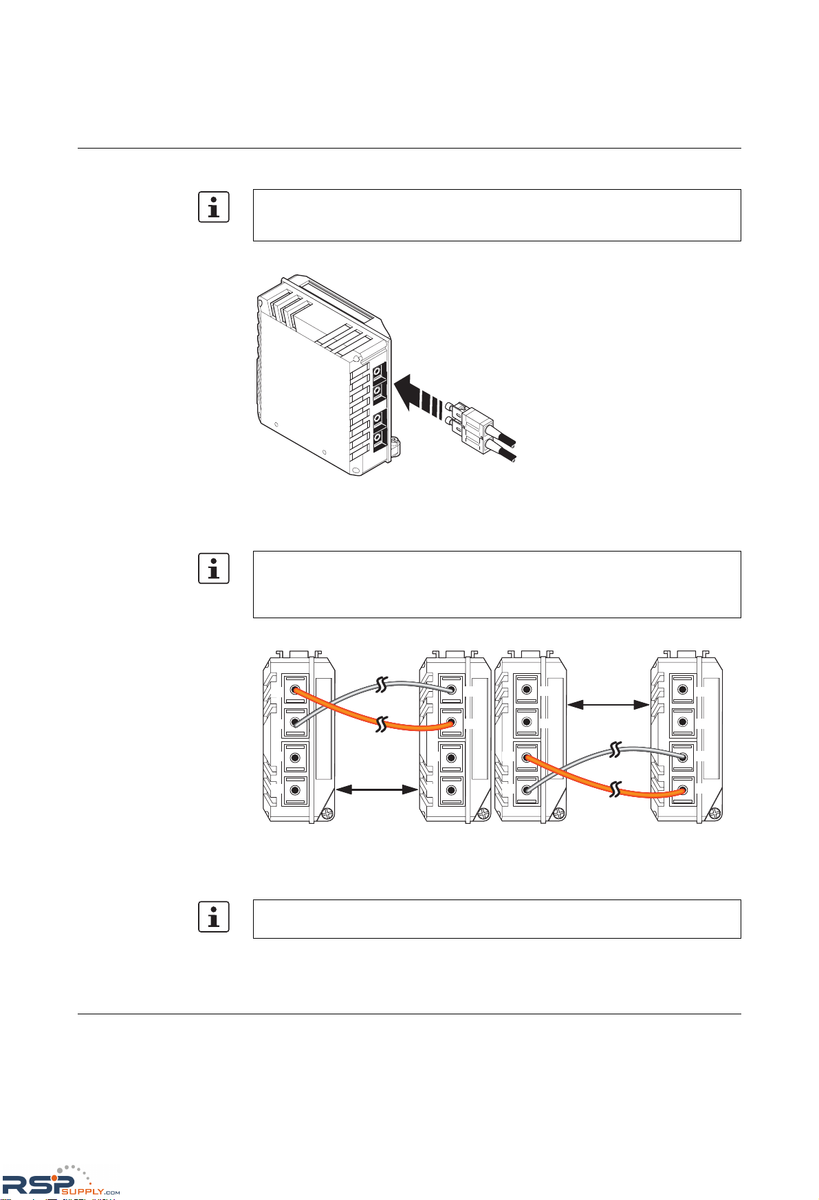
Product designation
3-18
PHOENIX CONTACT 6874_en_16
3.3.4.3 Connecting the SC-D connectors
Figure 3-14 Connecting the SC-D connectors
3.3.4.4 Fiber optic connection between devices
Figure 3-15 Fiber optic connection between devices
To prevent dirt from entering the connectors, do not remove the dust protection caps until
just before connecting the connectors. The same applies for the protective caps on the
connectors.
6 8 7 4 0 0 2 0
When connecting two fiber optic interface modules, note the signal direction of the fiber
optics. The fiber connection is always from the transmitter to the receiver. The
SC-D/SCRJ connectors, which are connected using a support, are keyed to ensure that
the assignment of the transmit and receive direction is correct.
68741021
Max. 36000 m
Single mode
glass fiber
RX
RX
TX
TX
RX
TX
RX
TX
Max. 10000 m
Multi-mode
glass fiber
RX
RX
TX
TX
RX
TX
RX
TX
FL IF 2FX SC-F FL IF 2FX SC-F
FL IF 2FX SM SC-F
FL IF 2FX SM SC-F
The maximum length of the fiber optic cables depends on the interface module/fiber type
used.
RSPSupply - 1-888-532-2706 - www.RSPSupply.com
http://www.RSPSupply.com/p-14178-Phoenix-Contact-2832357-FL-IF-2TX-VS-RJ-D-Media-Module-for-Modular-Switch.aspx
Page 65
Startup and functions
6874_en_16 PHOENIX CONTACT 3-19
3.3.5 FL IF 2FX ST-D
3.3.5.1 Default upon delivery
When the interface modules are inserted, they are preset with a data transmission rate of
100 Mbps and full duplex mode, and link monitoring is not activated for the glass fiber ports.
3.3.5.2 Functions
–Line monitoring
According to standard IEEE 802.3, the switch monitors the connected fiber optic cables
for interrupts.
– Far End Fault Detection indicates that the connection in the direction of the partner is
not OK (the partner does not indicate a link) and therefore at least one fiber within the
glass fiber cable is faulty or has not been assembled correctly.
NOTE: Please observe the following information on the FL IF 2FX …-D Interface modules
Affected Interface modules:
FL IF 2FX SC-D, HW: 05,
FL IF 2FX SM SC-D, HW: 03,
FL IF 2FX ST-D, HW: 01,
The use of the above-named Interface modules with the specified hardware status is
restricted in the FL SWITCH MM HS modular managed switch (Order no.: 2832328) and
the FL MXT (2832331) extension stations.
It is only possible to operate one of the above-mentioned modules in the head station of
the switch and one each in an extension station. An FL SWITCH MMS can be operated
with two extension stations, i.e. a maximum of 3 FL IF 2FX …-D modules. All other IF
modules can be operated in any constellation.
Operation of the Interface module in FL SWITCH GHS …G/… Gigabit Modular Switches
is possible without restriction.
Interface modules with older hardware status as the above mentioned can be operated in
all modular switches.
Older replacement modules can be ordered according to revision. Please contact your
Phoenix Contact sales representative.
Hot plugging
When inserting and removing interface modules, you do not have to switch off the supply
voltage. The interface modules are detected automatically and logged to the network
management.
If the FL IF 2FX ST-D interface is removed and another interface type is inserted in its
place, the ports are set to auto negotiation.
If a glass fiber interface module is inserted in a MMS that has already been parameterized,
the existing configuration remains active.
– The data transmission rate is set to 100 Mbps
– The duplex method is set to full duplex
If the module is removed, auto negotiation is enabled.
Ports that are not being used are considered cable interrupts. In addition, a glass fiber path
to a deactivated termination device is also considered a cable interrupt, as the connected
device cannot send a link test pulse because it is switched off.
RSPSupply - 1-888-532-2706 - www.RSPSupply.com
http://www.RSPSupply.com/p-14178-Phoenix-Contact-2832357-FL-IF-2TX-VS-RJ-D-Media-Module-for-Modular-Switch.aspx
Page 66
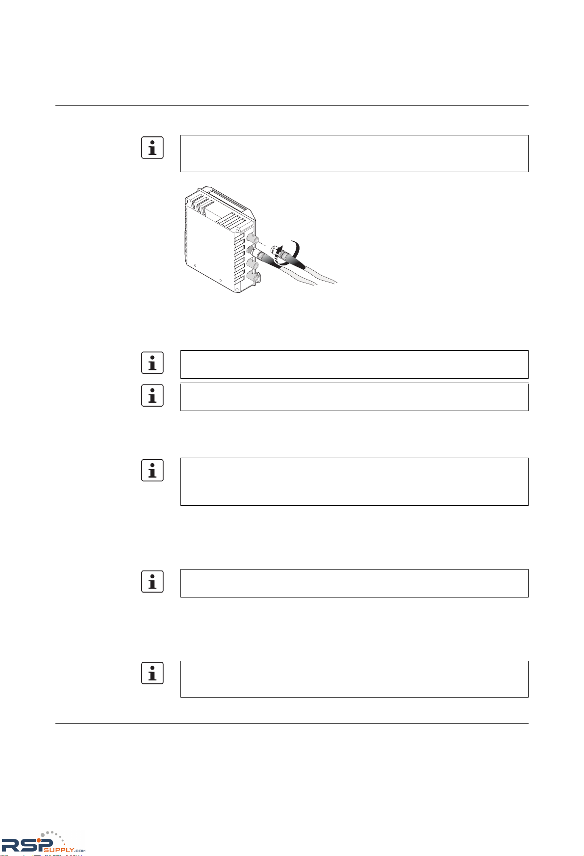
Product designation
3-20
PHOENIX CONTACT 6874_en_16
3.3.5.3 Connecting the ST connectors
Figure 3-16 Connecting the ST connectors
3.3.5.4 Glass fiber connection between devices
3.3.6 FL IF TX/POF 10/100 ...
3.3.6.1 Default upon delivery
When the interface modules are inserted, the auto negotiation and auto crossing functions
are activated for the twisted pair port, and the auto negotiation function is activated for the
POF port. Port monitoring is not activated for the two ports.
3.3.6.2 Functions of the POF interface
–Line monitoring
According to standard IEEE 802.3, the switch monitors the connected fiber optic cables
for interrupts.
To prevent dirt from entering the connectors, do not remove the dust protection caps until
just before connecting the connectors. The same applies for the protective caps on the
connectors.
When connecting two glass fiber interface modules, note the signal direction of the fiber
optics. The fiber connection is always from the transmitter to the receiver.
The maximum length of the glass fiber cables depends on the fiber type used.
Hot plugging
When inserting and removing interface modules, you do not have to switch off the supply
voltage. The interface modules are detected automatically and logged to the network
management.
If an interface module is inserted in a MMS that has already been parameterized, the
existing configuration remains active.
Ports that are not being used are considered cable interrupts. In addition, a POF path to a
deactivated termination device is also considered a cable interrupt, as the connected
device cannot send a link test pulse because it is switched off.
RSPSupply - 1-888-532-2706 - www.RSPSupply.com
http://www.RSPSupply.com/p-14178-Phoenix-Contact-2832357-FL-IF-2TX-VS-RJ-D-Media-Module-for-Modular-Switch.aspx
Page 67
Startup and functions
6874_en_16 PHOENIX CONTACT 3-21
–Auto negotiation
Auto negotiation is a method whereby the switch automatically detects the operating
parameters for the connected network and sets the corresponding parameters
(10 Mbps/100 Mbps data transmission rate and half/full duplex transmission mode) for
its F-SMA ports. Automatic port setting eliminates the need for manual intervention by
the user. The auto negotiation function can be activated/deactivated via the web
interface.
3.3.6.3 Functions of the twisted pair interface
–Auto negotiation
Auto negotiation is a method whereby the switch automatically detects the operating
parameters for the connected network and sets the corresponding parameters
(10 Mbps/100 Mbps data transmission rate and half/full duplex transmission mode) for
its RJ45 ports. Automatic port setting eliminates the need for manual intervention by the
user. The auto negotiation function can be activated/deactivated via the web interface.
– Auto crossing
There is no need to distinguish between 1:1 and crossover cables, as the transmit and
receive cables are crossed automatically.
– Auto polarity
The polarity is changed automatically by the switch if a pair of twisted pair receive
cables (RD+ and RD-) are connected incorrectly.
–Line monitoring
The switch uses link test pulses according to standard IEEE 802.3 at regular intervals
to monitor the connected TP/TX cable segments for short circuits and interrupts.
3.3.6.4 Network connection
See "Assignment of F-SMA ports to the DIP switch" on page 3-14 and onwards, and
"Reducing the transmission power" on page 3-13 and onwards.
3.3.7 FL IF TX/HCS 100 ...
Auto crossing is only available if auto negotiation is activated.
Ports that are not being used are considered cable interrupts. In addition, a TP/TX path to
a deactivated termination device is also considered a cable interrupt, as the connected
device cannot send a link test pulse because it is switched off.
The switch position for transmission power reduction will only be indicated in the web
interface in future hardware versions.
Hot plugging
When inserting and removing interface modules, you do not have to switch off the supply
voltage. The interface modules are detected automatically and logged to the network
management.
RSPSupply - 1-888-532-2706 - www.RSPSupply.com
http://www.RSPSupply.com/p-14178-Phoenix-Contact-2832357-FL-IF-2TX-VS-RJ-D-Media-Module-for-Modular-Switch.aspx
Page 68
Product designation
3-22
PHOENIX CONTACT 6874_en_16
3.3.7.1 Default upon delivery
When the interface modules are inserted, the auto negotiation and auto crossing functions
are activated for the twisted pair port, and the data transmission rate is set to 100 Mbps full
duplex for the HCS port. Port monitoring is not activated for the two ports.
3.3.7.2 Functions of the HCS interface
–Line monitoring
According to standard IEEE 802.3, the switch monitors the connected fiber optic cables
for interrupts.
3.3.7.3 Functions of the twisted pair interface
–Auto negotiation
Auto negotiation is a method whereby the switch automatically detects the operating
parameters for the connected network and sets the corresponding parameters
(10 Mbps/100 Mbps data transmission rate and half/full duplex transmission mode) for
its RJ45 ports. Automatic port setting eliminates the need for manual intervention by the
user. The auto negotiation function can be activated/deactivated via the web interface.
– Auto crossing
There is no need to distinguish between 1:1 and crossover cables, as the transmit and
receive cables are crossed automatically.
– Auto polarity
The polarity is changed automatically by the switch if a pair of twisted pair receive
cables (RD+ and RD-) are connected incorrectly.
–Line monitoring
The switch uses link test pulses according to standard IEEE 802.3 at regular intervals
to monitor the connected TP/TX cable segments for short circuits and interrupts.
3.3.7.4 Network connection
See "FL IF 2TX VS-RJ ..." on page 3-10 and onwards, and "FL IF 2HCS 100 ..." on
page 3-15 and onwards.
If an interface module is inserted in a MMS that has already been parameterized, the
existing configuration remains active.
Ports that are not being used are considered cable interrupts. In addition, an HCS path to
a deactivated termination device is also considered a cable interrupt, as the connected
device cannot send a link test pulse because it is switched off.
Auto crossing is only available if auto negotiation is activated.
Ports that are not being used are considered cable interrupts. In addition, a TP/TX path to
a deactivated termination device is also considered a cable interrupt, as the connected
device cannot send a link test pulse because it is switched off.
RSPSupply - 1-888-532-2706 - www.RSPSupply.com
http://www.RSPSupply.com/p-14178-Phoenix-Contact-2832357-FL-IF-2TX-VS-RJ-D-Media-Module-for-Modular-Switch.aspx
Page 69
Startup and functions
6874_en_16 PHOENIX CONTACT 3-23
3.3.8 FL IF MEM 2TX-D/FL IF MEM 2TX-D/MRM
The interface module has two twisted pair interfaces in addition to the parameterization
memory. To distinguish it from other 2TX interface modules, it is supplied in charcoal-gray
housing. The parameterization memory is used to store device data, which is modified by
the user and stored retentively.
3.3.8.1 Parameterization memory default upon delivery
By default upon delivery, the parameterization memory is empty (see "Default upon
delivery/default settings" on page 3-1).
3.3.8.2 Twisted pair interface default upon delivery
When the interface modules are inserted, the auto negotiation and auto crossing functions
are activated. Link monitoring for the twisted pair ports is not activated.
3.3.8.3 Function of the memory module
– When saving data to the Flash memory of the device, the data is also transmitted to a
plugged-in memory module.
The function/application of the FL IF MEM 2TX-D/MRM is described in Section "Media
Redundancy Protocol (MRP)" on page 6-1.
NOTE: If the FL SWITCH MM HS with two FL MXT extension modules is additionally
operated with one FL IF MEM 2TX-D memory module and up to four FL IF POF SCRJ-D
interface modules at the same time, the arrangement according to Section "Arrangement
of the interface modules" on page 2-7 must be observed.
Make sure that only one memory module is inserted. If more than one module is inserted,
the switch indicates error code "87" on the display. Remove all but one of the memory
modules and restart the switch.
The memory module is supported by firmware Version 2.03 or later. Firmware Versions
< 2.03 treat the memory module as a "standard" FL IF 2TX VS-RJ.
The use of memory modules requires the application of system bus firmware 4.20 or later
in the head station. The system bus firmware for your head station is displayed on the
"Device Information/General" web page.
Hot plugging
When inserting and removing interface modules, you do not have to switch off the supply
voltage. The interface modules are detected automatically and logged to the network
management.
If the module is removed when saving, the configuration is not saved. The saving
procedure is finished as soon as the display no longer indicates "SC" or when the status
"Current Configuration was saved" is indicated on the "Configuration Management"
web page.
If an interface module is inserted in a MMS that has already been parameterized, the
existing configuration remains active.
If the user resets the module to the settings default upon delivery, the configuration is also
saved on the memory module. See "Default upon delivery/default settings" on page 3-1.
RSPSupply - 1-888-532-2706 - www.RSPSupply.com
http://www.RSPSupply.com/p-14178-Phoenix-Contact-2832357-FL-IF-2TX-VS-RJ-D-Media-Module-for-Modular-Switch.aspx
Page 70
Product designation
3-24
PHOENIX CONTACT 6874_en_16
– Data is stored to the Flash memory of the head station and in the memory module:
- After a system startup
- On request by the user
– When starting the MMS, the data is read from a plugged-in memory module (display
indicates "OP") and used as the active configuration. The data in the Flash memory is
overwritten by the data from the memory module.
3.3.8.4 Functions of the twisted pair interface
–Auto negotiation
Auto negotiation is a method whereby the switch automatically detects the operating
parameters for the connected network and sets the corresponding parameters
(10 Mbps/100 Mbps data transmission rate and half/full duplex transmission mode) for
its RJ45 ports. Automatic port setting eliminates the need for manual intervention by the
user. The auto negotiation function can be activated/deactivated via the web interface.
– Auto crossing
There is no need to distinguish between 1:1 and crossover cables, as the transmit and
receive cables are crossed automatically.
– Auto polarity
The polarity is changed automatically by the switch if a pair of twisted pair receive
cables (RD+ and RD-) are connected incorrectly.
–Line monitoring
The switch uses link test pulses according to standard IEEE 802.3 at regular intervals
to monitor the connected TP/TX cable segments for short circuits and interrupts.
3.3.8.5 Network connection
See "FL IF 2TX VS-RJ ..." on page 3-10 and onwards.
3.3.9 FL IF 2PSE-F
Please note that the password stored on the memory module is also transmitted to the
MMS. Make sure that you know the password for the configuration on the memory module.
Auto crossing is only available if auto negotiation is activated.
Ports that are not being used are considered cable interrupts. In addition, a TP/TX path to
a deactivated termination device is also considered a cable interrupt, as the connected
device cannot send a link test pulse because it is switched off.
The PoE interface module is supported by firmware Version 4.0 or later. Firmware
Versions < 4.0 treat the module as a standard RJ45 interface module. The module can
operate in PoE mode without management and without support from the firmware and
hardware (system bus) (see note below). No configuration options and no diagnostic data
are available, connected termination devices are nevertheless supplied with power.
The use of the PoE interface module requires the application of system bus firmware 5.00
or later in the head station and system bus firmware 4.00 or later in the extension modules.
If this requirement is not met in the head station or in any extension module, then PoE
management is not available in the entire system. The system bus firmware is displayed
on the "Device Information/General" web page.
RSPSupply - 1-888-532-2706 - www.RSPSupply.com
http://www.RSPSupply.com/p-14178-Phoenix-Contact-2832357-FL-IF-2TX-VS-RJ-D-Media-Module-for-Modular-Switch.aspx
Page 71
Startup and functions
6874_en_16 PHOENIX CONTACT 3-25
Features of PoE mode
– Up to twelve PoE interface modules with a total of 24 ports can be operated at the same
time in a MMS.
– Configuration is still possible if the interface module is not plugged in or the
48 V supply is not connected.
– PoE management and PoE information are only available if the interface module is
plugged in and there is a connected 48 V supply.
– The following management functions are available:
- Display error states for each port and communicate via the alarm contact
(yes/no)
- Connect/disconnect voltage for each port
- Switch current limitation on or off for loads classified as Class 1 devices
– Send Traps when the PoE status changes
– The following diagnostic information is displayed:
- No error
- Surge voltage/undervoltage
- Thermal error
- Overload
- Disconnected load (the current consumption at this port is less than 10 mA, the supply
voltage is disconnected by the PoE module)
- No 48 V supply
- No PoE interface module detected at this port
- No hardware support due to the system bus
- Detected class of a connected termination device (Class 0 to Class 4)
- Output voltage and output current
3.3.9.1 Default upon delivery
When the interface modules are inserted, the auto negotiation and auto crossing functions
are activated. Link monitoring for the twisted pair ports is not activated.
3.3.9.2 Functions
–Auto negotiation
Auto negotiation is a method whereby the switch automatically detects the operating
parameters for the connected network and sets the corresponding parameters
(10 Mbps or 100 Mbps data transmission rate and half or full duplex transmission
mode) for its RJ45 ports. Automatic port setting eliminates the need for manual
intervention by the user. The auto negotiation function can be activated/deactivated via
the web interface.
PoE management and PoE information are only available if the 48 V supply is connected
to the relevant PoE interface module. The ports can be used as standard RJ45 ports if
there is no connected supply.
Hot plugging
When inserting and removing interface modules, you do not have to switch off the supply
voltage. The interface modules are detected automatically and logged to the network
management.
If an interface module is inserted in a MMS that has already been parameterized, the
existing configuration remains active.
RSPSupply - 1-888-532-2706 - www.RSPSupply.com
http://www.RSPSupply.com/p-14178-Phoenix-Contact-2832357-FL-IF-2TX-VS-RJ-D-Media-Module-for-Modular-Switch.aspx
Page 72
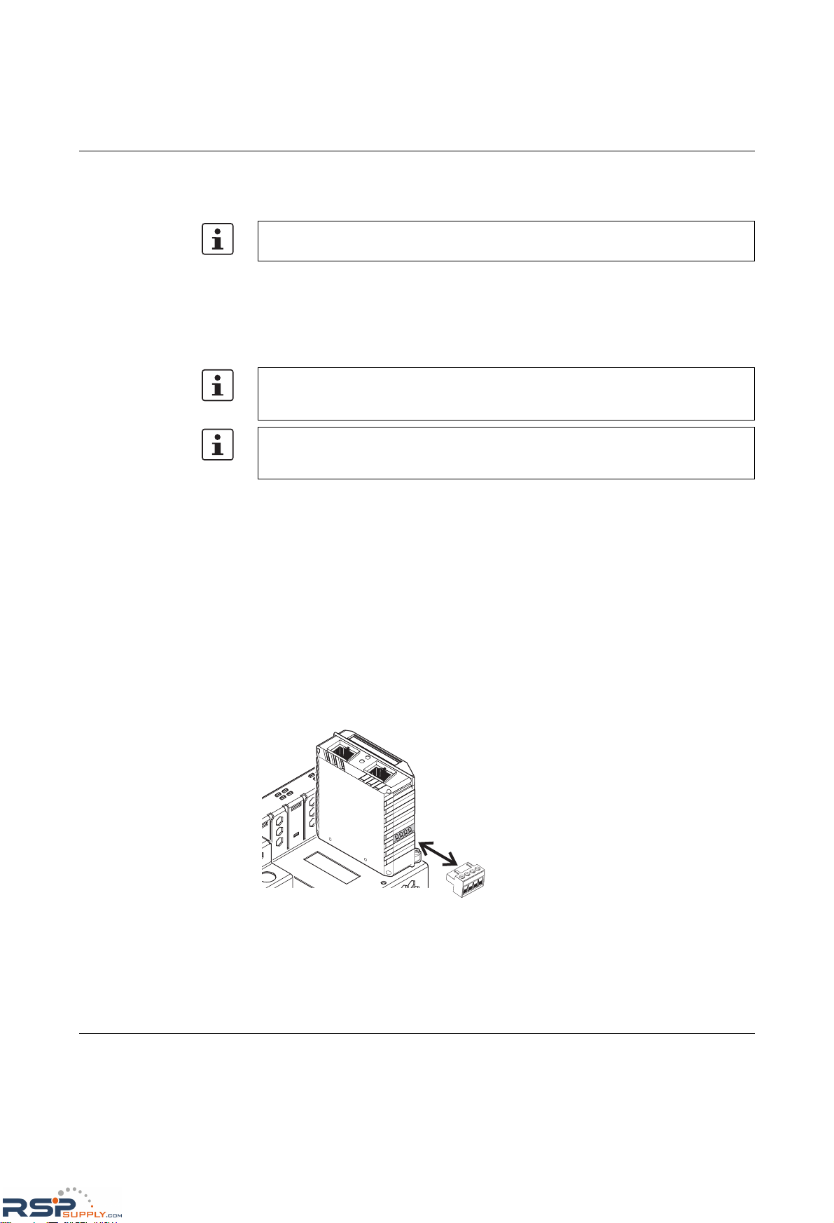
Product designation
3-26
PHOENIX CONTACT 6874_en_16
– Auto crossing
There is no need to distinguish between 1:1 and crossover cables, as the transmit and
receive cables are crossed automatically.
– Auto polarity
The polarity is changed automatically by the switch if a pair of twisted pair receive
cables (RD+ and RD-) are connected incorrectly.
–Line monitoring
The switch uses link test pulses according to standard IEEE 802.3 at regular intervals
to monitor the connected TP/TX cable segments for short circuits and interrupts.
3.3.9.3 Network connection
See "FL IF 2TX VS-RJ ..." on page 3-10 and onwards.
3.3.9.4 Connecting the 48 V PoE supply voltage
Connecting the PoE supply
The connector for the PoE supply is located on the bottom of the interface module. Please
observe the keying on the connector when inserting it.
The module has a green LED for each port, which indicates the PoE mode. The LED is
active if the PoE supply and a PD (powered device) are connected. The LED flashes if the
module is supplied with less than 48 V.
Figure 3-17 Connecting the PoE voltage connector
Auto crossing is only available if auto negotiation is activated.
Ports that are not being used are considered cable interrupts. In addition, a TP/TX path to
a deactivated termination device is also considered a cable interrupt, as the connected
device cannot send a link test pulse because it is switched off.
The PoE configuration options are also available if no PoE interface module is inserted. If
a PoE interface module is inserted, the configuration is transmitted to the module after a
few seconds.
121
2
RSPSupply - 1-888-532-2706 - www.RSPSupply.com
http://www.RSPSupply.com/p-14178-Phoenix-Contact-2832357-FL-IF-2TX-VS-RJ-D-Media-Module-for-Modular-Switch.aspx
Page 73
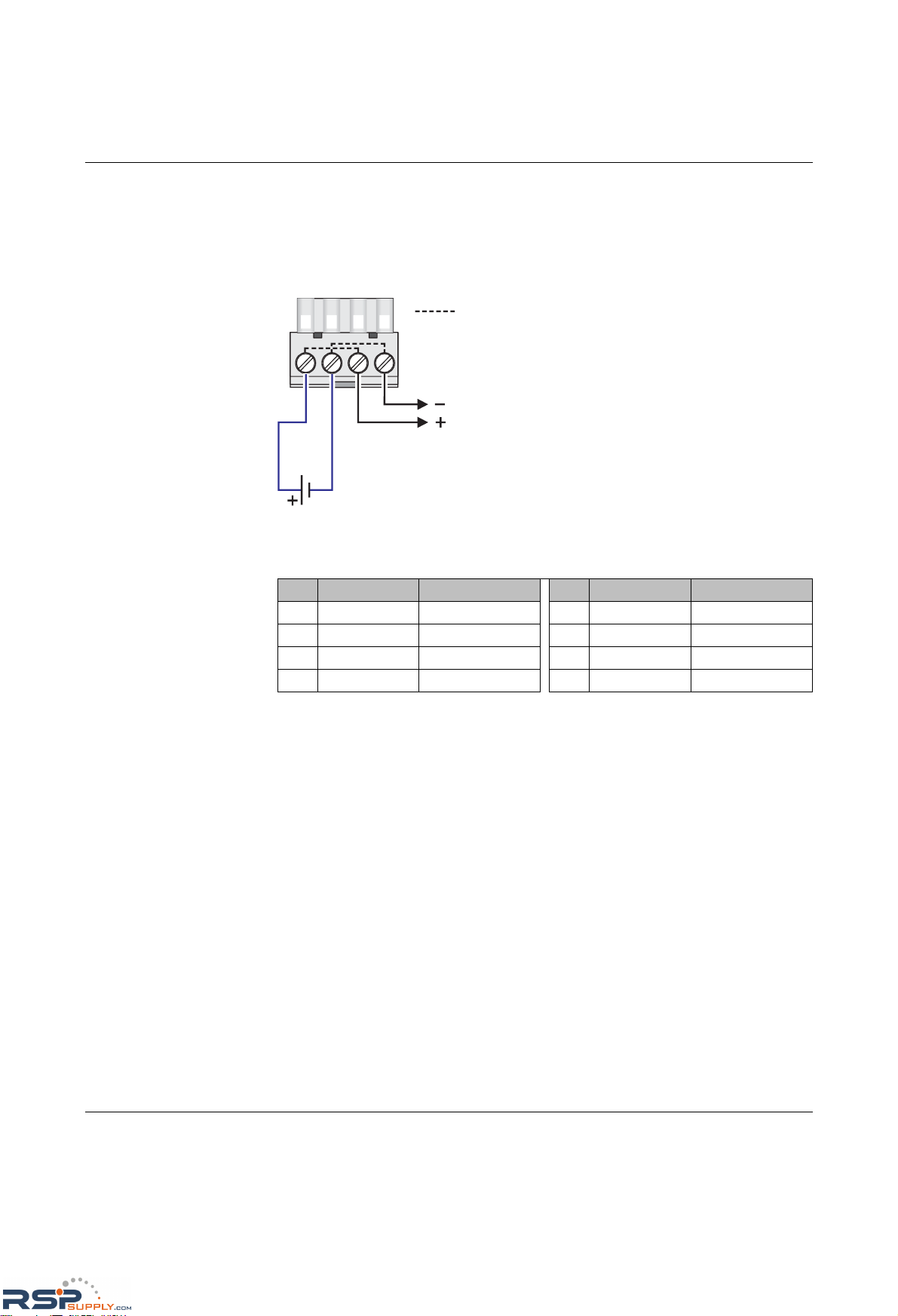
Startup and functions
6874_en_16 PHOENIX CONTACT 3-27
Connecting the PoE supply
Connect the 48 V PoE supply to terminals 1 (+) and 2 (-). The terminals are bridged within
the module. The bridges are located between terminals 1 and 3, and between terminals 2
and 4. The bridges can be used to supply voltage to a maximum of three additional PoE
interface modules. The supply voltage to additional PoE interface modules must be
supplied by power supply units.
Figure 3-18 Connecting the 48 V PoE supply
Table 3-3 Pin assignment of PoE ports
Pin Assignment Description Pin Assignment Description
1 RX+/48 V DC Data/PoE + 5 n. c. -
2 RX-/48 V DC Data/PoE + 6 TX-/0 V Data/PoE -
3TX+/0 V Data/PoE - 7 n. c. -
4 n. c. - 8 n. c. -
48 V DC
1 234
Internal bridging in
the interface module
687407054
RSPSupply - 1-888-532-2706 - www.RSPSupply.com
http://www.RSPSupply.com/p-14178-Phoenix-Contact-2832357-FL-IF-2TX-VS-RJ-D-Media-Module-for-Modular-Switch.aspx
Page 74
Product designation
3-28
PHOENIX CONTACT 6874_en_16
3.3.10 FL IF 2POF SCRJ-D
3.3.10.1 Default upon delivery
When the interface modules are inserted, they are preset with a data transmission rate of
100 Mbps and full duplex mode, and link monitoring is not activated for the fiber optic ports.
3.3.10.2 Functions
–Line monitoring
According to standard IEEE 802.3, the switch monitors the connected fiber optic cables
for interrupts.
– Far End Fault Detection indicates that the connection in the direction of the partner is
not OK (the partner does not indicate a link) and therefore at least one fiber within the
fiber optic cable is faulty or has not been assembled correctly.
3.3.10.3 Connecting the SCRJ connectors
NOTE: If the FL SWITCH MM HS with two FL MXT extension modules is additionally
operated with one FL IF MEM 2TX-D memory module and up to four FL IF POF SCRJ-D
interface modules at the same time, the arrangement according to Section "Arrangement
of the interface modules" on page 2-7 must be observed.
Hot plugging
When inserting and removing interface modules, you do not have to switch off the supply
voltage. The interface modules are detected automatically and logged to the network
management.
If the FL IF 2POF SCRJ ... interface is removed and another interface type is inserted in its
place, the ports are set to auto negotiation.
If a fiber optic interface module is inserted in a MMS that has already been parameterized,
the existing configuration remains active.
– The data transmission rate is set to 100 Mbps
– The duplex method is set to full duplex
If the module is removed, auto negotiation is enabled.
Ports that are not being used are considered cable interrupts. In addition, a fiber optic path
to a deactivated termination device is also considered a cable interrupt, as the connected
device cannot send a link test pulse because it is switched off.
To prevent dirt from entering the connectors, do not remove the dust protection caps until
just before connecting the connectors. The same applies for the protective caps on the
connectors.
RSPSupply - 1-888-532-2706 - www.RSPSupply.com
http://www.RSPSupply.com/p-14178-Phoenix-Contact-2832357-FL-IF-2TX-VS-RJ-D-Media-Module-for-Modular-Switch.aspx
Page 75
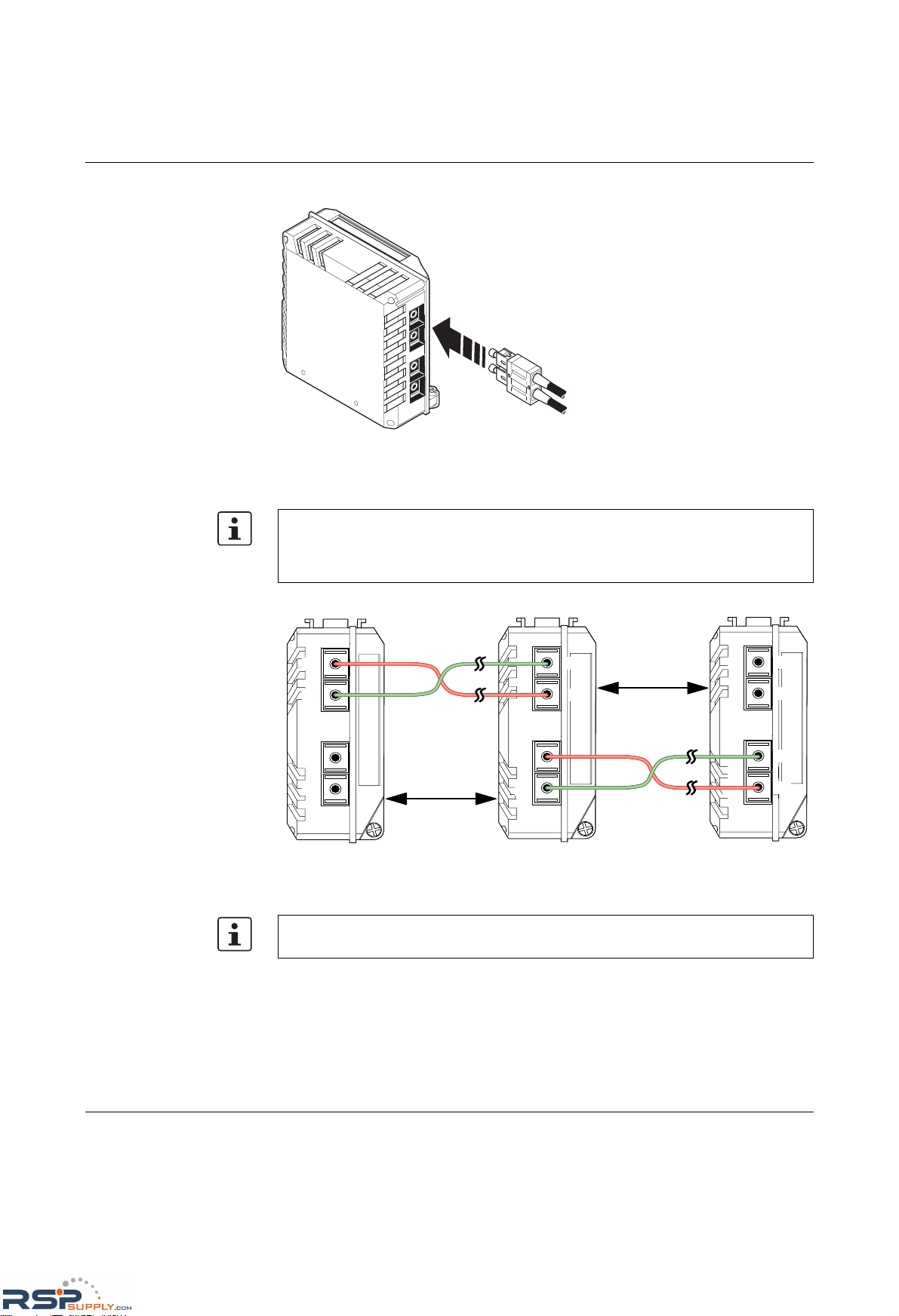
Startup and functions
6874_en_16 PHOENIX CONTACT 3-29
Figure 3-19 Connecting the SCRJ connectors
3.3.10.4 Fiber optic connection between devices
Figure 3-20 Fiber optic connection between devices
3.3.10.5 SCRJ modules in WBM
Very detailed information about the SCRJ modules is available in WBM (see Section
""Ports/POF Port Table" menu" on page 4-29), e.g., the port system reserve, alarms or port
states are displayed.
6 8 7 4 0 0 2 0
When connecting two fiber optic interface modules, note the signal direction of the fiber
optics. The fiber connection is always from the transmitter to the receiver. The SCRJ
connectors, which are connected using a support, are keyed to ensure that the
assignment of the transmit and receive direction is correct.
687409061
Max. 300 m
HCS fiber
Max. 50 m
Polymer fiber
FL IF 2POF SCRJ-D
FL IF 2POF SCRJ-D
FL IF 2POF SCRJ-D
RX
RX
TX
TX
RX
RX
TX
TX
RX
TX
RX
TX
The maximum length of the fiber optic cables depends on the interface module/fiber type
used.
RSPSupply - 1-888-532-2706 - www.RSPSupply.com
http://www.RSPSupply.com/p-14178-Phoenix-Contact-2832357-FL-IF-2TX-VS-RJ-D-Media-Module-for-Modular-Switch.aspx
Page 76
Product designation
3-30
PHOENIX CONTACT 6874_en_16
The following states can be displayed under "Transceiver status":
– "System Hardware does not support diagnosable POF modules" (this hardware does
not support POF-SCRJ diagnostics)
– "No POF-SCRJ Interface modules present" (no POF-SCRJ module is plugged in)
–"POF-SCRJ Interface module is present and OK" (the system reserve is greater than
2 dB and is displayed under "RX system reserve")
– "POF-SCRJ Interface module is present, but the system reserve is low" (the system
reserve is less than 2 dB, but greater than 0 dB)
–"POF-SCRJ Interface module is present, but the system reserve is exhausted" (no
system reserve available - the received optical power is below the required minimum
value)
The actual value of the system reserve can read by the Profinet engeneering and also be
used for Profinet alarms.
RSPSupply - 1-888-532-2706 - www.RSPSupply.com
http://www.RSPSupply.com/p-14178-Phoenix-Contact-2832357-FL-IF-2TX-VS-RJ-D-Media-Module-for-Modular-Switch.aspx
Page 77
Startup and functions
6874_en_16 PHOENIX CONTACT 3-31
3.4 Frame switching
The MMS/MCS operates in store-and-forward mode. When receiving a data packet, the
switch analyzes the source and destination addresses. The switch stores up to 8000 MAC
addresses with an adjustable aging time of 10 to 825 seconds in its address table.
3.4.1 Store-and-forward
All data telegrams that are received by the switch are saved and their validity is checked.
Invalid or faulty data packets (> 1522 bytes or CRC errors) and fragments (< 64 bytes) are
rejected. Valid data telegrams are forwarded by the switch.
3.4.2 Multi-address function
The switch learns all the source addresses for each port. Only packets with:
– Unknown source addresses
– A source address for this port
– A multicast/broadcast address
are forwarded to the destination address field via the relevant port. The switch can learn up
to 8000 addresses. This is important when more than one termination device is connected
to one or more ports. In this way, several independent subnetworks can be connected to
one switch.
3.4.3 Learning addresses
The switch independently learns the addresses for termination devices, which are
connected via a port, by evaluating the source addresses in the data telegram. When the
MMS/MCS receives a data telegram, it only forwards this data telegram to the port that
connects to the specified device (if the address could be learned beforehand).
The devices can learn up to 8000 addresses and store them in a table. The switch monitors
the age of the learned addresses. The switch automatically deletes address entries from its
address table that have exceeded a specific age (default: 40 seconds, adjustable from 10
to 825 seconds, aging time).
All learned entries are deleted on a restart.
A list of detected MAC addresses can be found in the MAC address table (see Section
""Diagnostics/MAC Address Table" menu" on page 4-40). The MAC address table can be
deleted via "Clear".
The aging time is set using the "dot1dTpAgingTime" MIB object
(OID 1.3.6.1.2.1.17.4.2). The available setting range is 10 - 825 seconds. For static
configuration, an aging time of 300 seconds is recommended.
RSPSupply - 1-888-532-2706 - www.RSPSupply.com
http://www.RSPSupply.com/p-14178-Phoenix-Contact-2832357-FL-IF-2TX-VS-RJ-D-Media-Module-for-Modular-Switch.aspx
Page 78

Product designation
3-32
PHOENIX CONTACT 6874_en_16
3.4.4 Prioritization
The switch supports two priority queues for adjusting the internal packet processing
sequence (traffic classes according to IEEE 802.1D). Data telegrams that are received are
assigned to these classes according to their priority, which is specified in the
VLAN/prioritization tag:
– Data packets with values between "0" and "3" in the priority field are low (default)
priority.
– Data packets with values between "4" and "7" in the priority field are transmitted via the
switch with high priority.
In addition, the switch enables port-based prioritization of data streams.
3.4.4.1 VLAN/prioritization tag
The MMS/MCS processes incoming data packets with regard to the prioritization
information contained in the Ethernet packet (VLAN/prioritization tag).
The tag enables the specification of a priority level from 0 to 7, which the switch assigns to
one of its two internal queues. By default upon delivery, the packets with priorities from 0 to
3 are treated as low-priority packets whereas packets with priorities from 4 to 7 are highpriority Ethernet packets.
The assignment of priority levels for both internal priority levels of the MMS can be modified
via the "dot1dTrafficClassTable" of the P bridge MIB.
Processing rules
The switch controller in the MMS/MCS forwards received packets to one of the receive
queues according to the following decisions:
– BPDU packets (Spanning Tree, LLDP) and IGMP packets are always assigned to the
high-priority queue.
– Packets with unknown unicast addresses are always assigned to the low-priority
queue.
– Packets are assigned to the high-priority queue if the priority from the VLAN/priority tag
is mapped to the "high" level (default priority 4 to 7).
– The internal port priority "high" results in priority level 7 handling, i.e., the basic settings
for data packet assignment to the high-priority queue are made.
– All residual data is assigned to the low-priority queue.
3.4.4.2 Port prioritization
In addition to the processing sequence according to the priority information from the tag, the
user can set the internal prioritization for every individual switch port at the MMS/MCS. In
this way, the processing of Ethernet data for a particular port can be prioritized.
The port prioritizing method is suitable for termination devices that do not support tagging
and thus cannot generate priorities.
"High" port prioritization sets the internal priority of the packets received at this port to
priority level 7. In the switch, these packets will be processed with priority information 7
within the tag (preferred handling and forwarding method only within the switch, however,
when forwarding to the receiver, the packets are in the original state). The "Low" port
prioritization means that the priority of packets received at this port is not influenced by the
switch. This implies that existing tags must be taken into consideration or that other priority
rules must be observed.
RSPSupply - 1-888-532-2706 - www.RSPSupply.com
http://www.RSPSupply.com/p-14178-Phoenix-Contact-2832357-FL-IF-2TX-VS-RJ-D-Media-Module-for-Modular-Switch.aspx
Page 79
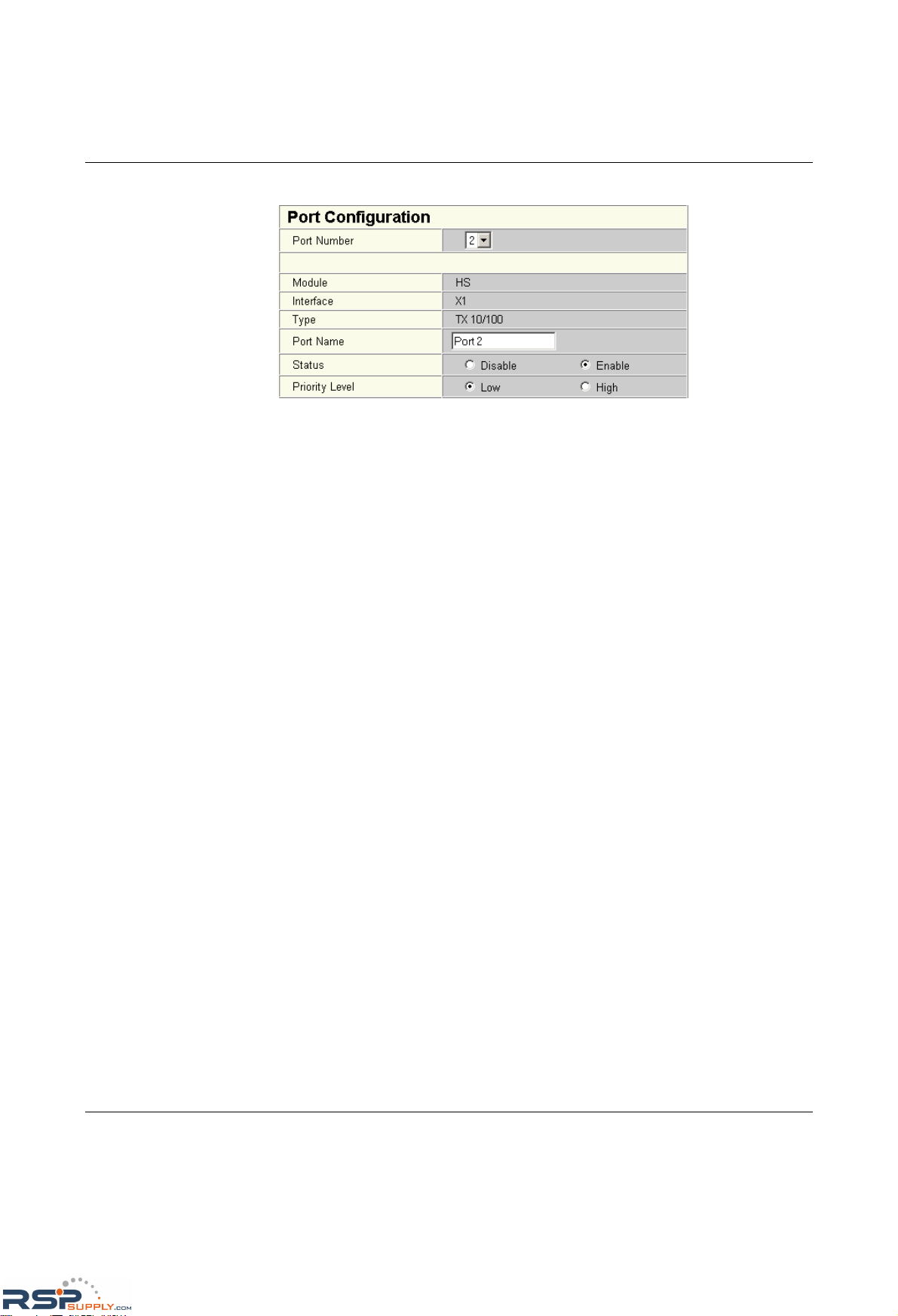
Startup and functions
6874_en_16 PHOENIX CONTACT 3-33
Setting the port priority
Figure 3-21 Setting the port priority
– On the "Port Configuration" web page, both available priority levels can be selected
under "Priority Level".
3.4.4.3 Strict priority
The switch supports two priority queues for adjusting the packet processing sequence
(traffic classes according to IEEE 802.1D). Data telegrams that are received are assigned
to these classes according to their priority, which is specified in the VLAN/prioritization tag:
– Data packets with values between "0" and "3" in the priority field are low priority
(default).
– Data packets with values between "4" and "7" in the priority field are transmitted via the
switch with high priority.
The MMS/MCS uses "Strict Priority" for transmitting data telegrams. First, all high-priority
data packets are assigned, once these are forwarded, low-priority telegrams are assigned.
This function prevents delays in high-priority data transmission, due to large volumes of lowpriority data traffic. Low-priority traffic is rejected when the memory or data channel is
overloaded.
RSPSupply - 1-888-532-2706 - www.RSPSupply.com
http://www.RSPSupply.com/p-14178-Phoenix-Contact-2832357-FL-IF-2TX-VS-RJ-D-Media-Module-for-Modular-Switch.aspx
Page 80

Product designation
3-34
PHOENIX CONTACT 6874_en_16
RSPSupply - 1-888-532-2706 - www.RSPSupply.com
http://www.RSPSupply.com/p-14178-Phoenix-Contact-2832357-FL-IF-2TX-VS-RJ-D-Media-Module-for-Modular-Switch.aspx
Page 81
Configuration and diagnostics
6874_en_16 PHOENIX CONTACT 4-1
4 Configuration and diagnostics
The MMS/MCS offers several user interfaces for accessing configuration and diagnostic
data. The preferred interfaces are the web interface and SNMP interface. These two
interfaces can be used to make all the necessary settings and request all information.
Access via Telnet/V.24 (RS-232) interface only enables access to basic information.
However, the V.24 (RS-232) interface also enables firmware update via XMODEM in the
event of faulty firmware.
4.1 Factory Manager
4.1.1 General function
The integration of the MMS/MCS in the Factory Manager provides optimum support for
configuration and management.
4.1.2 Assigning IP parameters
Once you have established all the necessary connections and Factory Manager has been
started, start the MMS/MCS or execute a reset.
Following the boot phase, the MMS/MCS sends the BootP requests, which are received by
the Factory Manager and displayed in the message window. If you are operating other
devices in the same network, messages from these devices may also be displayed.
Messages from Phoenix Contact Factory Line components can be easily identified by their
MAC address, which starts with 00.A0.45... and is provided on the devices.
Settings are not automatically saved permanently. The active configuration can be saved
permanently by selecting "Save current configuration" on the "Configuration
Management" web page.
Only one of several options for assigning IP parameters using Factory Manager 2.2 is
described here.
Please check the MAC address in the messages to ensure the correct device is
addressed.
RSPSupply - 1-888-532-2706 - www.RSPSupply.com
http://www.RSPSupply.com/p-14178-Phoenix-Contact-2832357-FL-IF-2TX-VS-RJ-D-Media-Module-for-Modular-Switch.aspx
Page 82
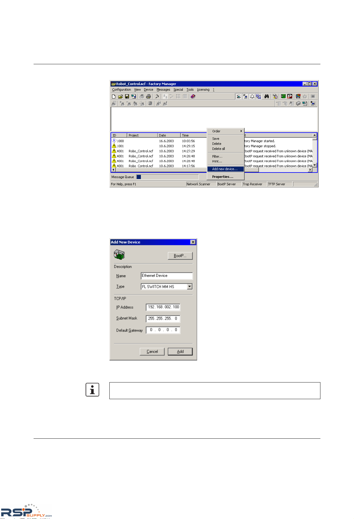
FL SWITCH MM HS
4-2
PHOENIX CONTACT 6874_en_16
Figure 4-1 Messages from the MMS/MCS in the Factory Manager
Right-click on one of the MMS/MCS messages and select the "Add new device..." menu
item. Under "Description", select an icon and enter a device name.
Specify the desired IP parameters under "TCP/IP" (see also Section "Assigning IP
parameters" on page 3-4).
Figure 4-2 Input mask for IP parameters
Make sure that the assignment of IP parameters via BootP is also activated.
RSPSupply - 1-888-532-2706 - www.RSPSupply.com
http://www.RSPSupply.com/p-14178-Phoenix-Contact-2832357-FL-IF-2TX-VS-RJ-D-Media-Module-for-Modular-Switch.aspx
Page 83
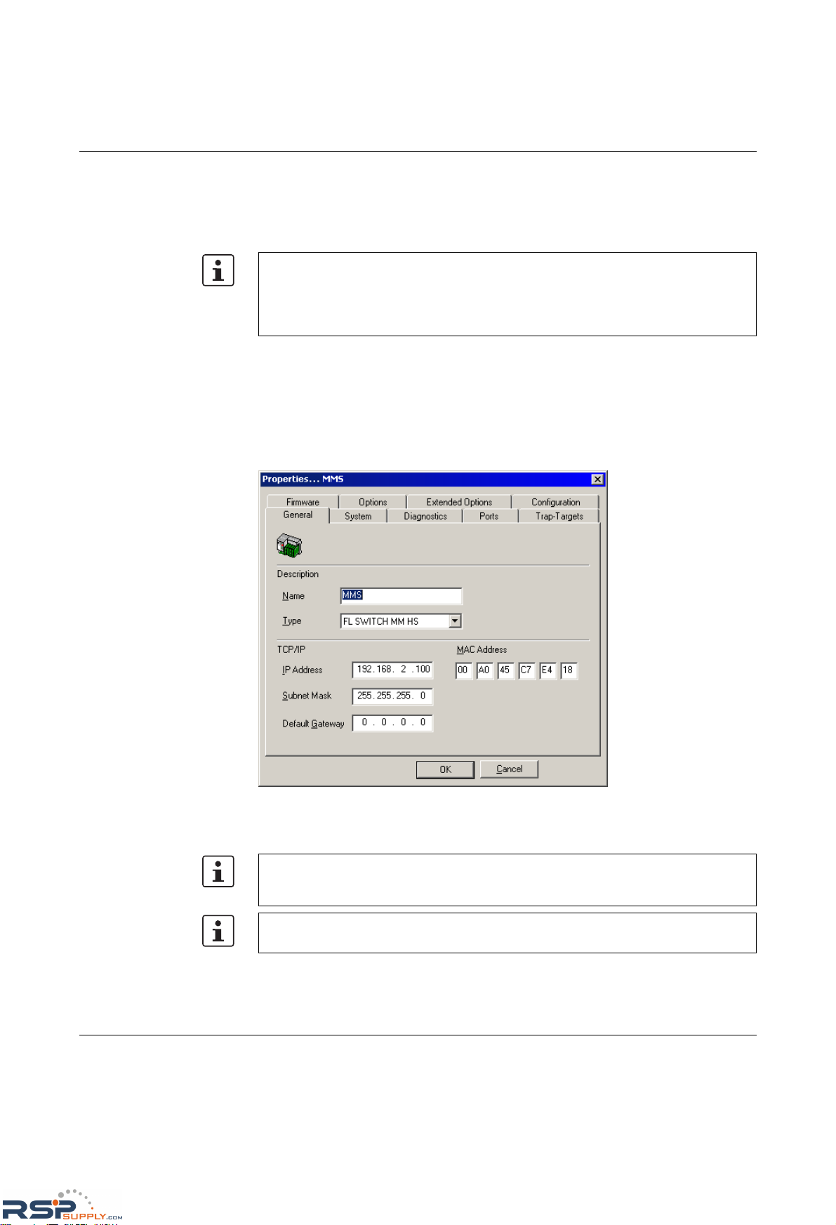
Configuration and diagnostics
6874_en_16 PHOENIX CONTACT 4-3
Once you have clicked on "Add", the device is added to the project and is indicated as
unavailable. You must now restart or reset the MMS/MCS. Following a restart, the
MMS/MCS resends the BootP requests and receives the corresponding BootP reply from
the Factory Manager. Once the boot process has been completed the MMS/MCS is
indicated as available.
4.1.3 Configuration and diagnostics
Numerous options for configuring and diagnosing the MMS/MCS can be found in the
"Device" menu under "Properties".
General
Figure 4-3 "General" menu
Here you can check or modify device names and types as well as IP parameters.
If the MMS/MCS is still indicated as "unavailable", check your network card settings.
Please note that both devices must be located in the same network/subnetwork. If the
Factory Manager receives the BootP requests this does not mean that the devices are
located in the same subnetwork, as the BootP requests are sent as a broadcast beyond
subnetwork boundaries.
If you modify the IP address and/or the other IP parameters using the Factory Manager,
once you click "OK" you will no longer have access via the Factory Manager. Restarting
the MMS/MCS activates the modified parameters and restores access.
To activate the new addresses following a restart, BootP must be activated in the
MMS/MCS (on the "IP Configuration" page in WBM).
RSPSupply - 1-888-532-2706 - www.RSPSupply.com
http://www.RSPSupply.com/p-14178-Phoenix-Contact-2832357-FL-IF-2TX-VS-RJ-D-Media-Module-for-Modular-Switch.aspx
Page 84
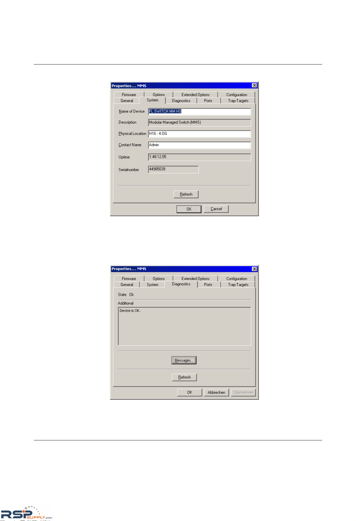
FL SWITCH MM HS
4-4
PHOENIX CONTACT 6874_en_16
System
Figure 4-4 "System" menu
In this menu, you can add additional information in the white fields, which will be saved on
the MMS/MCS. This information is also available via SNMP and WBM.
Diagnostics
Figure 4-5 "Diagnostics" menu
RSPSupply - 1-888-532-2706 - www.RSPSupply.com
http://www.RSPSupply.com/p-14178-Phoenix-Contact-2832357-FL-IF-2TX-VS-RJ-D-Media-Module-for-Modular-Switch.aspx
Page 85
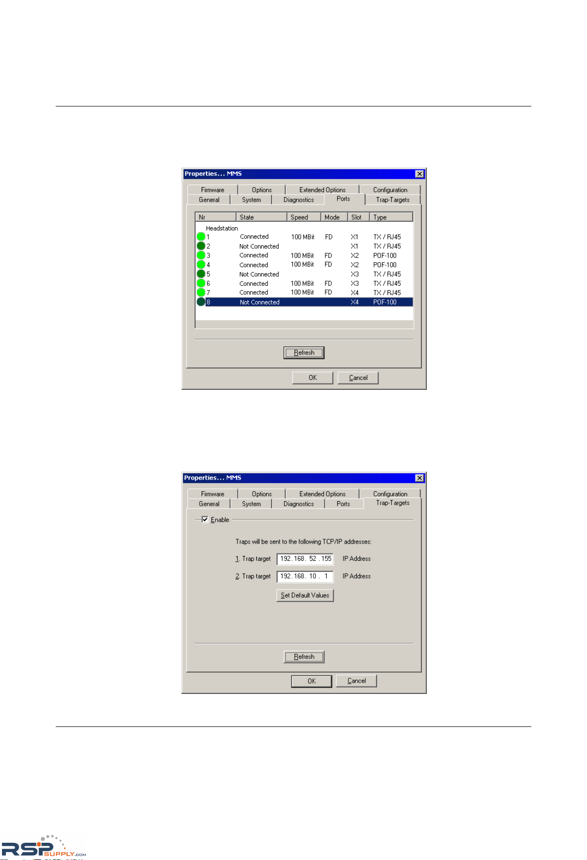
Configuration and diagnostics
6874_en_16 PHOENIX CONTACT 4-5
Information about the device status and redundancy is displayed here. All the messages for
this device are displayed under Messages.
Ports
Figure 4-6 "Ports" menu for the MMS
Comprehensive information, e.g., from interface types and states, through transmission
data to port levels, is displayed here. All information is automatically created and updated.
Trap Targets
Figure 4-7 "Trap Targets" menu
RSPSupply - 1-888-532-2706 - www.RSPSupply.com
http://www.RSPSupply.com/p-14178-Phoenix-Contact-2832357-FL-IF-2TX-VS-RJ-D-Media-Module-for-Modular-Switch.aspx
Page 86
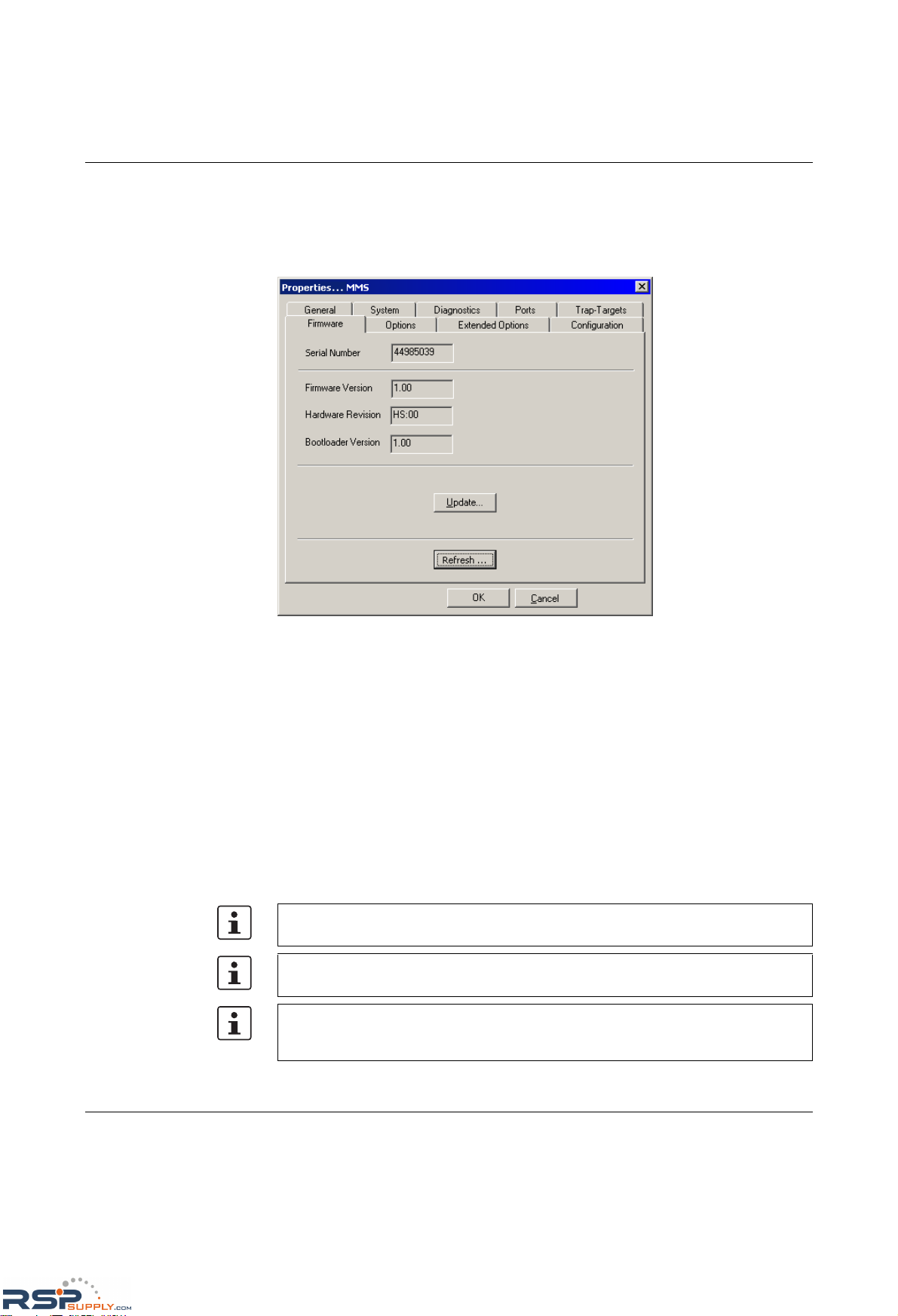
FL SWITCH MM HS
4-6
PHOENIX CONTACT 6874_en_16
Trap targets are displayed or set here, and the "send traps" function can be activated or
deactivated. Clicking on "Set Default Values" automatically activates the IP address of the
computer on which the Factory Manager is installed as the trap target.
Firmware
Figure 4-8 "Firmware" menu
Here you can view all information about the current device software (firmware). You can
also update the software/firmware using the Factory Manager.
Firmware update When you click on "Update", the following window appears, which contains information
about the firmware used.
During a firmware update, the current status is shown on the MMS display:
03 - Downloading firmware via the network.
04 - Saving the firmware in the MMS Flash memory.
05 - The new firmware has been saved successfully.
Display goes out.
bo - Device is booting and loading new firmware in the RAM.
Following a firmware update, a reset is executed automatically to activate the new
firmware.
Please make sure that the "TFTP Server" service program is activated in the toolbar.
You can monitor the download in the message window (25%, 50%, 75%, 100%). Always
wait until all the LEDs light up after approximately two minutes and the device is available
again after booting.
RSPSupply - 1-888-532-2706 - www.RSPSupply.com
http://www.RSPSupply.com/p-14178-Phoenix-Contact-2832357-FL-IF-2TX-VS-RJ-D-Media-Module-for-Modular-Switch.aspx
Page 87
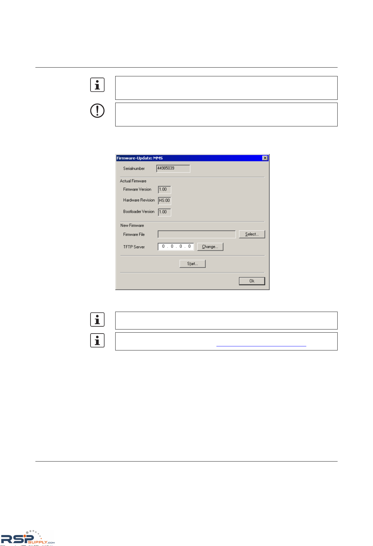
Configuration and diagnostics
6874_en_16 PHOENIX CONTACT 4-7
Update
Figure 4-9 "Update" menu
It is not ensured that all existing configuration data will be retained after a firmware
update/downgrade. Therefore, please check the configuration settings or return the
device to the settings default upon delivery.
NOTE: A voltage failure during a firmware update results in the destruction of the firmware
on the MMS/MCS. An update via XMODEM is required, see "Starting with faulty software
(firmware)" on page 4-127.
In order to enable a firmware update, the firmware image must be located in the
"Download" directory of the Factory Manager.
An application note for firmware update via TFTP (AH EN TFTP FIRMWARE UPDATE)
can be found in the Download Center at www.download.phoenixcontact.com
.
RSPSupply - 1-888-532-2706 - www.RSPSupply.com
http://www.RSPSupply.com/p-14178-Phoenix-Contact-2832357-FL-IF-2TX-VS-RJ-D-Media-Module-for-Modular-Switch.aspx
Page 88
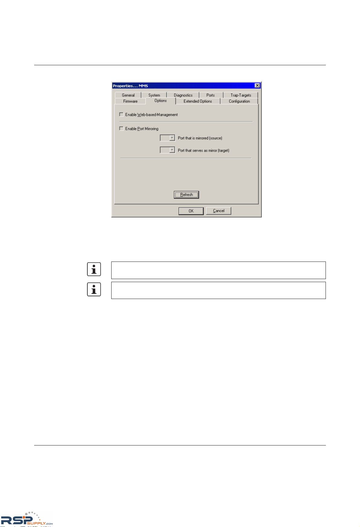
FL SWITCH MM HS
4-8
PHOENIX CONTACT 6874_en_16
Options
Figure 4-10 "Options" menu
Two functions are available for selection:
– Activate/deactivate the web server.
– Configure the port mirroring function.
If ports are set with the same value for the source and destination, port mirroring will be
disabled. The source port is set to "0".
Enter the destination port in the relevant multicast group in order to enable multicast
packets to be received at the set destination port.
RSPSupply - 1-888-532-2706 - www.RSPSupply.com
http://www.RSPSupply.com/p-14178-Phoenix-Contact-2832357-FL-IF-2TX-VS-RJ-D-Media-Module-for-Modular-Switch.aspx
Page 89
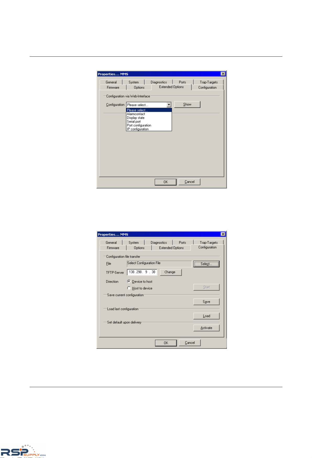
Configuration and diagnostics
6874_en_16 PHOENIX CONTACT 4-9
Extended Options
Figure 4-11 "Extended Options" menu
You can jump straight to the web interface from here via a selection menu. The relevant
function is described in "Web-based management (WBM)" on page 4-10 and onwards.
Configuration
Figure 4-12 "Configuration" menu
Various options are provided here for saving or loading the configuration.
RSPSupply - 1-888-532-2706 - www.RSPSupply.com
http://www.RSPSupply.com/p-14178-Phoenix-Contact-2832357-FL-IF-2TX-VS-RJ-D-Media-Module-for-Modular-Switch.aspx
Page 90
FL SWITCH MM HS
4-10
PHOENIX CONTACT 6874_en_16
4.2 Web-based management (WBM)
4.2.1 General function
Online diagnostics The user-friendly web-based management interface can be used to manage the switch from
anywhere in the network using a standard browser. Comprehensive configuration and
diagnostic functions are clearly displayed on a graphic user interface. Every user with a
network connection to the device has read access to that device via a browser. Depending
on the physical structure of the switch, a wide range of information about the device itself,
the set parameters, and the operating state can be viewed.
4.2.2 Requirements for the use of WBM
As the web server operates using the Hyper Text Transfer Protocol, a standard browser can
be used. Access is via the URL "http://IP address of the device".
Example: "http://172.16.29.112".
For full operation of the web pages, the browser must support JavaScript 1.2 and cascading
style sheets Level 1. We recommend the use of Microsoft Internet Explorer 6.0.
4.2.2.1 Structure of the web pages
The web pages are divided into four areas:
– Device type and device logo.
– Device name (assigned by the user) and loading time, to prevent mix-ups.
– Navigation tree on the left-hand side.
– Information tables, which contain current device information during runtime.
Most of the screenshots shown in Section 4.2, "Web-based management (WBM)" are for
the MMS. WBM for the MCS has the same configuration options; however the information
regarding extension modules does not apply (this is specific to the MMS).
Modifications can only be made by entering the valid password. By default upon delivery,
the password is "private".
For security reasons, we recommend you enter a new, unique password.
WBM can only be called using a valid IP address. By default upon delivery, the switch has
no valid IP address.
Settings are not automatically saved permanently. If the active configuration has not been
saved, a flashing floppy disk icon appears in the top-right corner in WBM. The icon is
linked to the "Configuration Management" web page. The active configuration can be
saved permanently by selecting "Save current configuration" on this web page.
RSPSupply - 1-888-532-2706 - www.RSPSupply.com
http://www.RSPSupply.com/p-14178-Phoenix-Contact-2832357-FL-IF-2TX-VS-RJ-D-Media-Module-for-Modular-Switch.aspx
Page 91
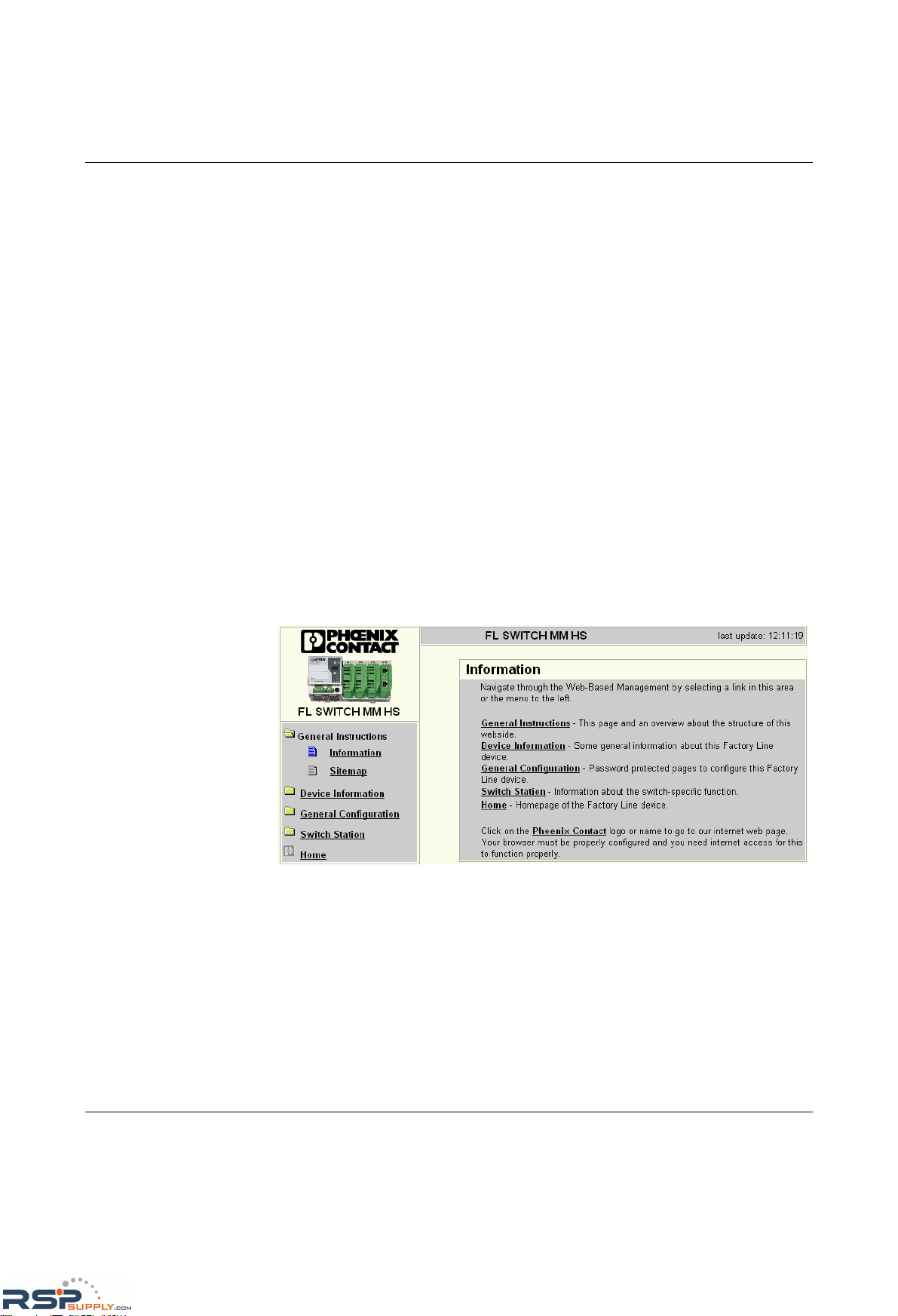
Configuration and diagnostics
6874_en_16 PHOENIX CONTACT 4-11
4.2.2.2 Password concept
After having entered the valid password, no further entry of the password is necessary for a
period of 300 s (default). After this period of time has elapsed or after clicking on "Logout",
the password must be re-entered.
The period of time can be set using the "flWorkFWCtrlLoginExpire" SNMP object within a
range of 30 s to 3600 s (default 300 s).
The concept is valid for the first ten users logged on at the same time. All other users must
confirm each configuration modification by entering the password, until less than ten users
are logged on.
4.2.3 Functions/information in WBM
The navigation tree provides direct access to the following four areas:
– General Instructions
Basic information about WBM.
– Device Information
General device information.
– General Configuration
Device configuration/device as a network device.
– Switch Station
Device-specific configuration and diagnostics.
4.2.3.1 General Instructions
Figure 4-13 "Information" web page for the MMS
General Instructions
Contains a brief description of WBM and a navigation tree (site map), which is linked to
every page of WBM.
RSPSupply - 1-888-532-2706 - www.RSPSupply.com
http://www.RSPSupply.com/p-14178-Phoenix-Contact-2832357-FL-IF-2TX-VS-RJ-D-Media-Module-for-Modular-Switch.aspx
Page 92
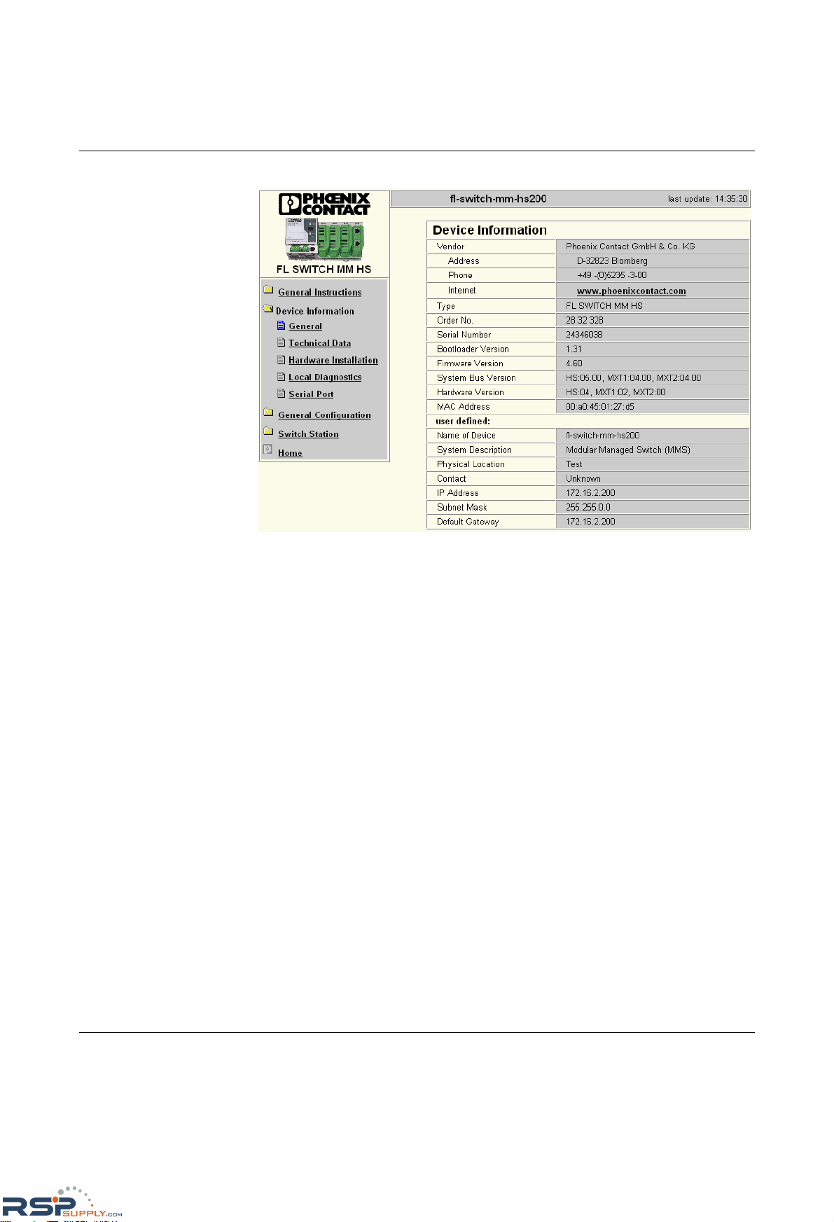
FL SWITCH MM HS
4-12
PHOENIX CONTACT 6874_en_16
4.2.3.2 Device Information
Figure 4-14 "Device Information" web page
"General" menu
This page contains a range of static information about the device and the manufacturer.
"Technical Data" menu
This page lists the main technical data.
"Hardware Installation" menu
This page contains a connection diagram for connecting the redundant power supply and
the alarm contact.
"Local Diagnostics" menu
This page describes the meaning of the switchable diagnostic and status indicators, and
lists the various display options for the 7-segment display.
"Serial Port" menu
This page lists the transmission parameters for serial communication.
RSPSupply - 1-888-532-2706 - www.RSPSupply.com
http://www.RSPSupply.com/p-14178-Phoenix-Contact-2832357-FL-IF-2TX-VS-RJ-D-Media-Module-for-Modular-Switch.aspx
Page 93
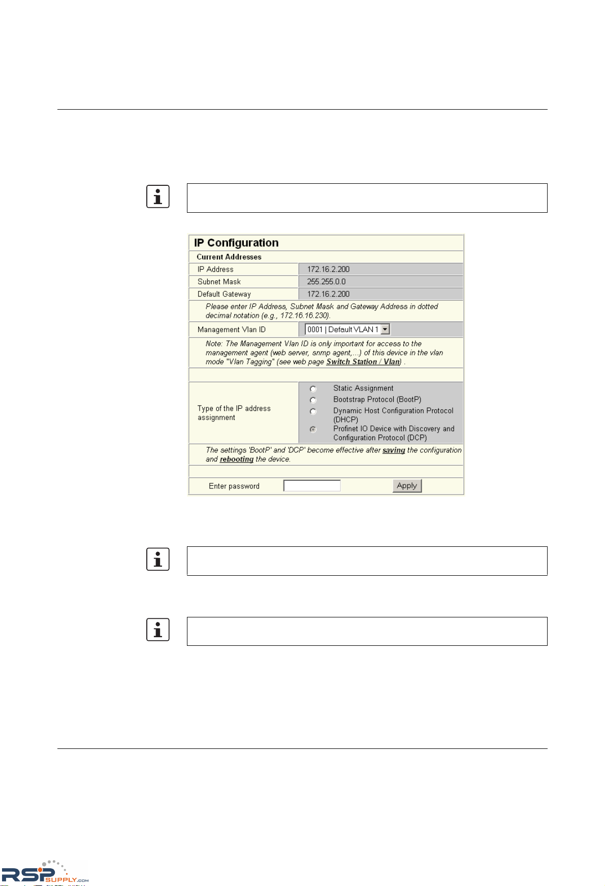
Configuration and diagnostics
6874_en_16 PHOENIX CONTACT 4-13
4.2.3.3 General Configuration
"IP Configuration" menu
This page displays the set IP parameters, management VLAN ID, and addressing
mechanism.
To change the IP parameters via WBM, "Static" assignment must be selected.
Figure 4-15 "IP Configuration" web page
IP address assignment
– Static Assignment
The switch can be accessed using the set IP address and does not send any kind of
requests on the receipt of IP parameters.
– Bootstrap Protocol (BootP)
The switch sends a BootP request after every restart and receives a BootP reply with
IP parameters. If the BootP reply is disabled, the switch starts after the third request with
the last IP parameters saved. If the switch has no saved IP parameters, the switch
continues to send BootP requests until it receives a response with a BootP reply.
The management VLAN ID specifies in which VLAN the switch can be accessed if it is
operating in "Tagging" VLAN mode.
While the switch waits for an IP address to be assigned - "01" or "dP" in the display - the
mode LED selected via the mode button also flashes.
If you modify the IP address and/or the other IP parameters via WBM, once you click on
"Apply" you will no longer have access via the IP address set in the browser.
RSPSupply - 1-888-532-2706 - www.RSPSupply.com
http://www.RSPSupply.com/p-14178-Phoenix-Contact-2832357-FL-IF-2TX-VS-RJ-D-Media-Module-for-Modular-Switch.aspx
Page 94
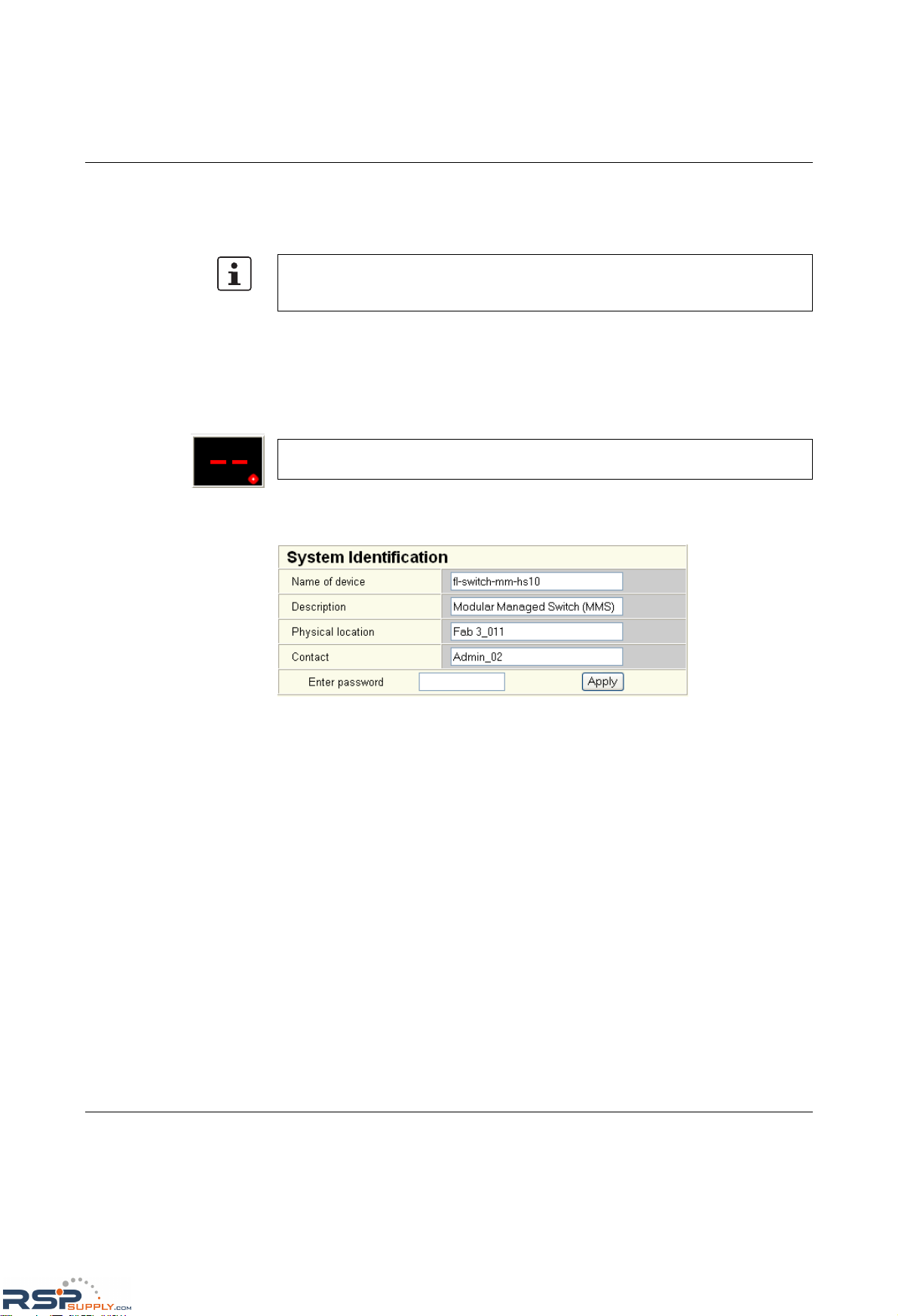
FL SWITCH MM HS
4-14
PHOENIX CONTACT 6874_en_16
– Dynamic Host Configuration Protocol (DHCP)
Once DHCP has been enabled, the switch attempts to apply network parameters from
a DHCP server. The setting, regardless of whether DHCP is enabled or not, is saved
permanently.
– Discovery and Configuration Protocol (DCP)
Mode for assigning IP addresses in PROFINET. After startup, the switch waits for the
startup of the IO controller or an engineering tool. This status is indicated by display
output "dP". The switch can only be accessed after configuration using the assigned IP
address. The assigned IP address is not saved permanently, which means that the
switch waits to be assigned an address every time the device starts. DCP is activated
automatically if "Profinet" mode is selected.
"System Identification" menu
This menu is used to display or modify user-specific device data, e.g., location, device
name or function. This device data is also available in SNMP.
Figure 4-16 "System Identification" menu
Once DHCP has be en enabled, th e di splay conta ins "01" and wait s for IP parame ters from
a DHCP server. As long as no IP parameters have been assigned by a DHCP server, the
switch can still be accessed via the previously set IP parameters.
If the MMS has established a PROFINET connection, a dot appears in the bottom-right
corner of the display.
RSPSupply - 1-888-532-2706 - www.RSPSupply.com
http://www.RSPSupply.com/p-14178-Phoenix-Contact-2832357-FL-IF-2TX-VS-RJ-D-Media-Module-for-Modular-Switch.aspx
Page 95
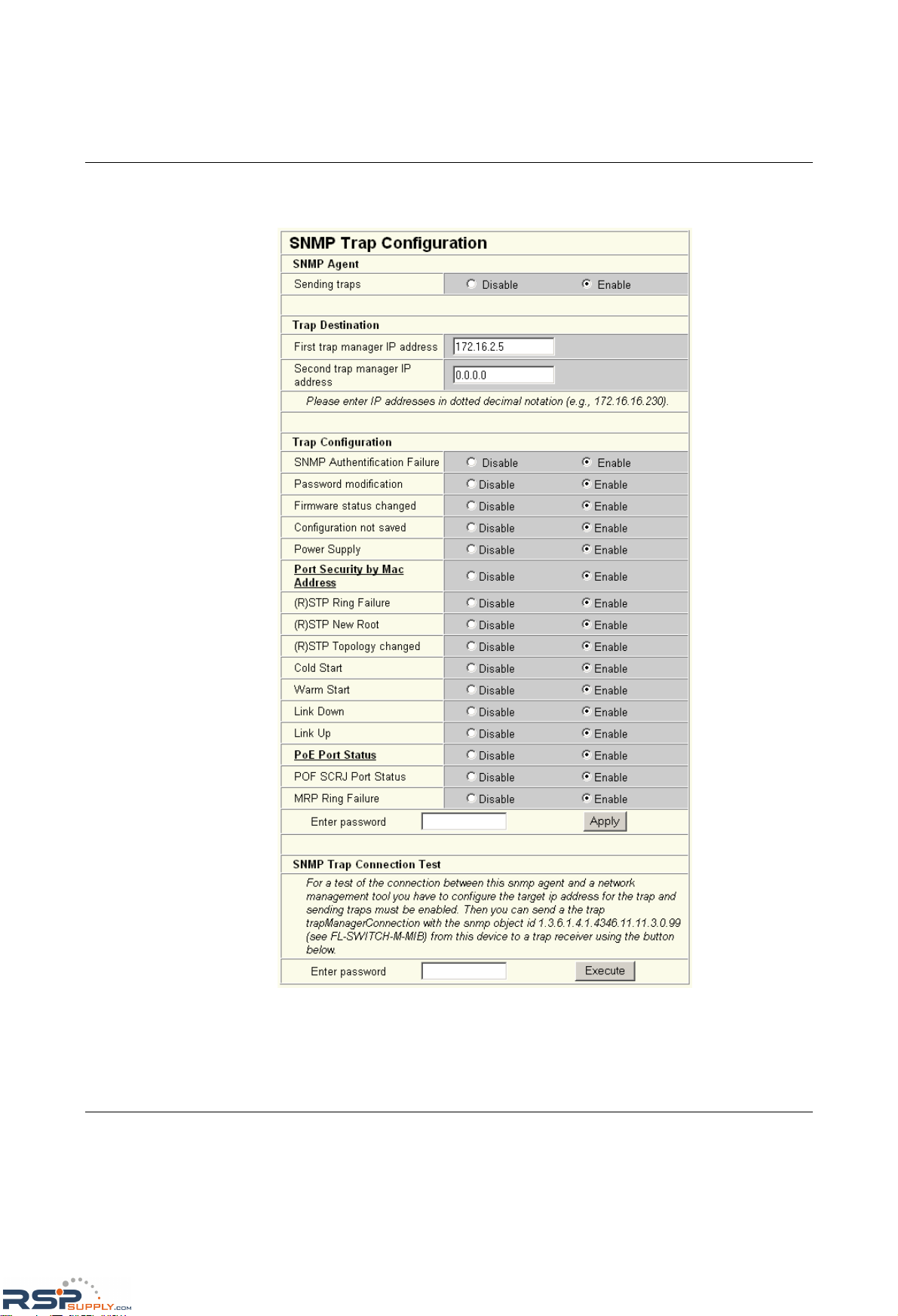
Configuration and diagnostics
6874_en_16 PHOENIX CONTACT 4-15
"SNMP Trap Configuration" menu
SNMP Agent The "send traps" function can be globally enabled/disabled here.
Figure 4-17 "SNMP Configuration" web page
Trap Destination This part of the table is used to view or modify the IP addresses of the two trap receivers.
RSPSupply - 1-888-532-2706 - www.RSPSupply.com
http://www.RSPSupply.com/p-14178-Phoenix-Contact-2832357-FL-IF-2TX-VS-RJ-D-Media-Module-for-Modular-Switch.aspx
Page 96

FL SWITCH MM HS
4-16
PHOENIX CONTACT 6874_en_16
Trap Configuration The "send traps" function can be disabled individually here.
SNMP Trap
Connection Test
Once the "send traps" function has been activated and the trap manager has been defined
using the IP addresses, test traps can now be sent using "Execute" to test the
communication path from the switch to the trap receiver.
4.2.3.4 "SNTP Configuration" menu
General information about SNTP
SNTP (Simple Network Time Protocol) is defined in RFC 4330 (SNTP clients in automation
technology) and is used to synchronize the internal system time with any NTP server, which
represents the "timer", i.e., the universal time. The aim is to synchronize all the components
in a network with the universal time and to thus create a uniform time base.
Time synchronization provides valuable assistance when evaluating error and event logs,
as the use of time synchronization in various network components enables events to be
assigned and analyzed more easily.
Clients should therefore only be used at the most extreme points of an NTP network. Time
synchronization is carried out at fixed synchronization intervals known as polling intervals.
The client receives a correction time by means of an SNTP server, with the packet runtime
for messages between the client and server being integrated in the time calculation in the
client. The local system time of the client is thus constantly corrected. Synchronization in the
NTP is carried out in Universal Time Coordinated (UTC) format.
The current system time is displayed as Universal Time Coordinates (UTCs). This means
that the displayed system time corresponds to Greenwich Mean Time. The system time and
the "UTC Offset" provide the current local time.
The switch supports the use of the SNTP protocol except in client mode, i.e., switches or
other network components only ever receive a time from a time server, but do not transmit
their own times.
– Each client synchronizes its system time with that of an SNTP server
– Time synchronization is carried out at fixed synchronization intervals
– The local system time of the client is thus constantly corrected
– Synchronization is carried out in Universal Time Coordinated (UTC) format
RSPSupply - 1-888-532-2706 - www.RSPSupply.com
http://www.RSPSupply.com/p-14178-Phoenix-Contact-2832357-FL-IF-2TX-VS-RJ-D-Media-Module-for-Modular-Switch.aspx
Page 97
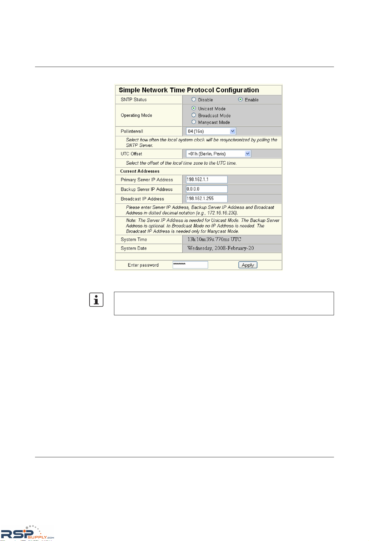
Configuration and diagnostics
6874_en_16 PHOENIX CONTACT 4-17
The parameters for automatic time synchronization using SNTP can be set here.
Figure 4-18 "Simple Network Time Protocol Configuration" menu
Configuration sequence
• Activate the SNTP function (Enable)
• Set the desired time zone with "UTC Offset"
• Under "Pollinterval", select the time slot pattern in which the system time is to be
updated
• Select the operating mode. Either:
Unicast Mode: The client receives its time from a fixed primary server.
Broadcast Mode: The client receives its time from broadcast messages, which were
transmitted by an NTP server and sent to several clients.
Manycast Mode: The client sends a broadcast message to several NTP servers. The
client selects the best response from the servers and then operates in unicast mode.
For the times in the event table, for example, make sure that the system time corresponds
to Greenwich Mean Time. The current local time is based on the system time and the "UTC
Offset".
RSPSupply - 1-888-532-2706 - www.RSPSupply.com
http://www.RSPSupply.com/p-14178-Phoenix-Contact-2832357-FL-IF-2TX-VS-RJ-D-Media-Module-for-Modular-Switch.aspx
Page 98
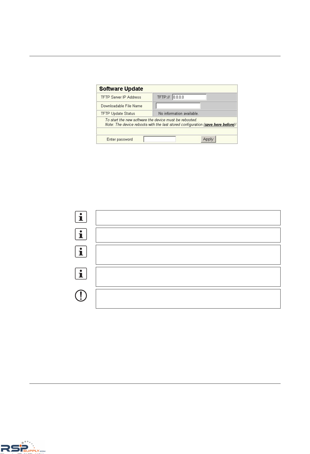
FL SWITCH MM HS
4-18
PHOENIX CONTACT 6874_en_16
4.2.3.5 "Software Update" menu
This page is used to view or modify the parameters for a software update and to trigger the
update.
Figure 4-19 "Software Update" web page
During a firmware update, the current status is shown on the MMS display:
03 - Downloading firmware via the network.
04 - Saving the firmware in the MMS Flash memory.
05 - The new firmware has been saved successfully.
Display goes out.
bo - Device is booting and loading new firmware in the RAM.
Following a firmware update, a reset is executed automatically to activate the new
firmware.
Please make sure that the "TFTP Server" service program is activated in the Factory
Manager toolbar.
You can monitor the download in the Factory Manager message
window (25%, 50%, 75%, 100%). Always wait until all the LEDs light up after
approximately two minutes and the device is available again after booting.
It is not ensured that all existing configuration data will be retained after a firmware
update/downgrade. Therefore, please check the configuration settings or return the
device to the settings default upon delivery.
NOTE: A voltage failure during a firmware update results in the destruction of the firmware
on the MMS/MCS. An update via XMODEM is required, see "Starting with faulty software
(firmware)" on page 4-127.
RSPSupply - 1-888-532-2706 - www.RSPSupply.com
http://www.RSPSupply.com/p-14178-Phoenix-Contact-2832357-FL-IF-2TX-VS-RJ-D-Media-Module-for-Modular-Switch.aspx
Page 99
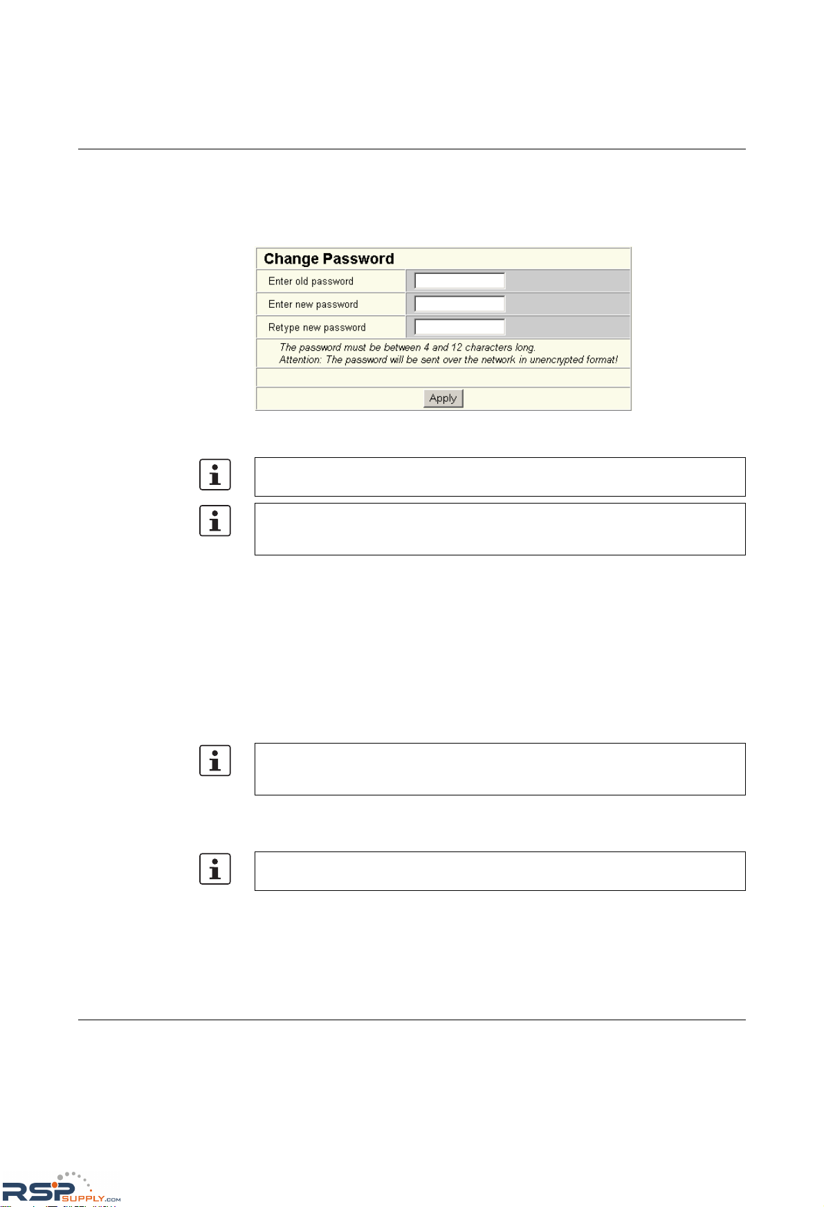
Configuration and diagnostics
6874_en_16 PHOENIX CONTACT 4-19
"Change Password" menu
This option can be used to specify the current password and then enter a new, unique
password. By default upon delivery, the password is "private" (please note that it is casesensitive). For security reasons, the input fields do not display your password, but instead
"*******" is displayed.
Figure 4-20 "Change Password" web page
"User Interfaces" menu
The following actions can be executed here:
– Activation/deactivation of the Telnet server.
– Activation/deactivation of the web server.
– Activation/deactivation of the SNMP agent.
– Activation/deactivation of the configuration pages for redundancy mechanisms.
– Activation/deactivation of the configuration pages for multicast filtering.
– Activation/deactivation of the configuration pages for VLAN.
– Activation/deactivation of the configuration pages for the DHCP relay agent.
– Setting the refresh intervals for the automatic update of the web pages. Here, you can
also set the refresh interval for automatic update of different web pages. If the interval
is set to "0", the pages will no longer be updated.
The password must be between four and twelve characters long. Please note that the
password is always transmitted via the network in unencrypted format.
Forgotten your password?
Call the Phoenix Contact phone number listed in the Appendix, making sure you have the
device serial number and MAC address to hand.
With the activation/deactivation of the configuration pages under "User Interfaces", only
the web pages for configuring the selected functions are enabled/disabled in the WBM
menu.
Automatic update of web pages is only possible when using Internet Explorer Version 5.5
or later.
RSPSupply - 1-888-532-2706 - www.RSPSupply.com
http://www.RSPSupply.com/p-14178-Phoenix-Contact-2832357-FL-IF-2TX-VS-RJ-D-Media-Module-for-Modular-Switch.aspx
Page 100
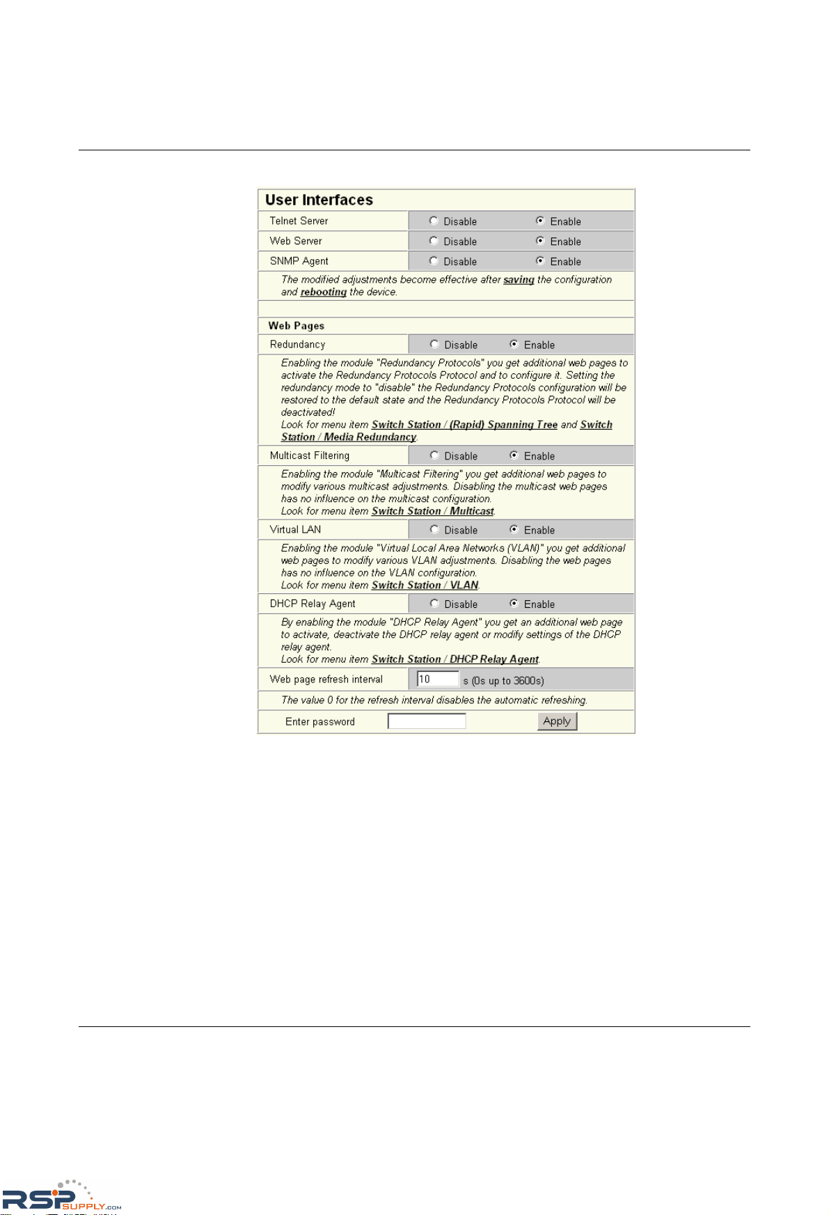
FL SWITCH MM HS
4-20
PHOENIX CONTACT 6874_en_16
Figure 4-21 "User Interfaces" web page
"Access Control" menu
Here you can specify the IP addresses from which access to the web interface is permitted.
To do so, enter the IP address in dotted notation and select whether read-only or read/write
access is to be assigned. As an option, another name can be assigned under "Description".
Access to WBM can be configured for a maximum of ten IP addresses.
RSPSupply - 1-888-532-2706 - www.RSPSupply.com
http://www.RSPSupply.com/p-14178-Phoenix-Contact-2832357-FL-IF-2TX-VS-RJ-D-Media-Module-for-Modular-Switch.aspx
 Loading...