

Page 1
AUTOMATION
UM QS EN FL SWITCH GHS for
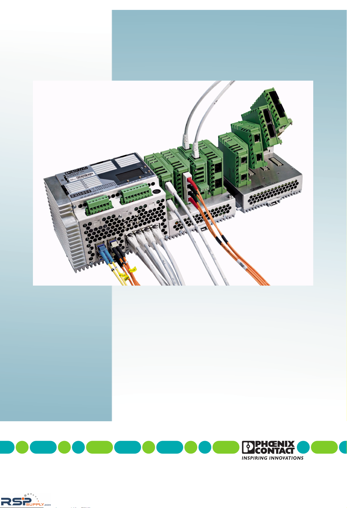
FL SWITCH GHS 12G/8
FL SWITCH GHS 4G/12
Quick Start Guide
Order No.: -
Gigabit Modular Switch
RSPSupply - 1-888-532-2706 - www.RSPSupply.com
http://www.RSPSupply.com/p-14161-Phoenix-Contact-2700271-FL-SWITCH-GHS-4G/12-Modular-Ethernet-Switch.aspx
Page 2

RSPSupply - 1-888-532-2706 - www.RSPSupply.com
http://www.RSPSupply.com/p-14161-Phoenix-Contact-2700271-FL-SWITCH-GHS-4G/12-Modular-Ethernet-Switch.aspx
Page 3

Designation:
Revision:
Order No.:
This user manual is valid for:
2010-03-03
AUTOMATION
8042_en_00 PHOENIX CONTACT
Quick start guide for access to the web-based management of the Gigabit Modular Switch
UM QS EN FL SWITCH GHS
00
—
Designation Revision Order No.
FL SWITCH GHS 2989200
FL SWITCH GHS 4G/12 2700271
FL FXT 2989307
Quick start guide
RSPSupply - 1-888-532-2706 - www.RSPSupply.com
http://www.RSPSupply.com/p-14161-Phoenix-Contact-2700271-FL-SWITCH-GHS-4G/12-Modular-Ethernet-Switch.aspx
Page 4
FL SWITCH GHS
PHOENIX CONTACT 8042_en_00
Please observe the following notes
In order to ensure the safe use of the product described, you have to read and understand
this manual. The following notes provide information on how to use this manual.
User group of this manual
The use of products described in this manual is oriented exclusively to qualified electricians
or persons instructed by them, who are familiar with applicable national standards and other
regulations regarding electrical engineering and, in particular, the relevant safety concepts.
Phoenix Contact accepts no liability for erroneous handling or damage to products from
Phoenix Contact or third-party products resulting from disregard of information contained in
this manual.
Explanation of symbols used and signal words
The following types of messages provide information about possible property damage and
general information concerning proper operation and ease-of-use.
This is the safety alert symbol. It is used to alert you to potential personal injury
hazards. Obey all safety measures that follow this symbol to avoid possible
injury or death.
DANGER
This indicates a hazardous situation which, if not avoided, will result in death or serious
injury.
WARNING
This indicates a hazardous situation which, if not avoided, will result in death or serious
injury.
CAUTION
This indicates a hazardous situation which, if not avoided, could result in minor or
moderate injury.
NOTE
This symbol and the accompanying text alerts the reader to a situation which may cause
damage or malfunction to the device, either hardware or software, or surrounding
property.
This symbol and the accompanying text provides additional information to the reader. It is
also used as a reference to other sources of information (manuals, data sheets, literature)
on the subject matter, product, etc.
RSPSupply - 1-888-532-2706 - www.RSPSupply.com
http://www.RSPSupply.com/p-14161-Phoenix-Contact-2700271-FL-SWITCH-GHS-4G/12-Modular-Ethernet-Switch.aspx
Page 5

8042_en_00 PHOENIX CONTACT
General terms and conditions of use for technical documentation
Phoenix Contact reserves the right to alter, correct, and/or improve the technical
documentation and the products described in the technical documentation at its own
discretion and without giving prior notice, insofar as this is reasonable for the user. The
same applies to any technical changes that serve the purpose of technical progress.
The receipt of technical documentation (in particular data sheets, installation instructions,
manuals, etc.) does not constitute any further duty on the part of Phoenix Contact to furnish
information on alterations to products and/or technical documentation. Any other
agreement shall only apply if expressly confirmed in writing by Phoenix Contact. Please
note that the supplied documentation is product-specific documentation only and that you
are responsible for checking the suitability and intended use of the products in your specific
application, in particular with regard to observing the applicable standards and regulations.
Although Phoenix Contact makes every effort to ensure that the information content is
accurate, up-to-date, and state-of-the-art, technical inaccuracies and/or printing errors in
the information cannot be ruled out. Phoenix Contact does not offer any guarantees as to
the reliability, accuracy or completeness of the information. All information made available
in the technical data is supplied without any accompanying guarantee, whether expressly
mentioned, implied or tacitly assumed. This information does not include any guarantees
regarding quality, does not describe any fair marketable quality, and does not make any
claims as to quality guarantees or guarantees regarding the suitability for a special purpose.
Phoenix Contact accepts no liability or responsibility for errors or omissions in the content
of the technical documentation (in particular data sheets, installation instructions, manuals,
etc.).
The aforementioned limitations of liability and exemptions from liability do not apply, in so
far as liability must be assumed, e.g., according to product liability law, in cases of
premeditation, gross negligence, on account of loss of life, physical injury or damage to
health or on account of the violation of important contractual obligations. Claims for
damages for the violation of important contractual obligations are, however, limited to
contract-typical, predictable damages, provided there is no premeditation or gross
negligence, or that liability is assumed on account of loss of life, physical injury or damage
to health. This ruling does not imply a change in the burden of proof to the detriment of the
user.
RSPSupply - 1-888-532-2706 - www.RSPSupply.com
http://www.RSPSupply.com/p-14161-Phoenix-Contact-2700271-FL-SWITCH-GHS-4G/12-Modular-Ethernet-Switch.aspx
Page 6

FL SWITCH GHS
PHOENIX CONTACT 8042_en_00
Statement of legal authority
This manual, including all illustrations contained herein, is copyright protected. Use of this
manual by any third party is forbidden. Reproduction, translation, and public disclosure, as
well as electronic and photographic archiving or alteration requires the express written
consent of Phoenix Contact. Violators are liable for damages.
Phoenix Contact reserves all rights in the case of patent award or listing of a registered
design. Third-party products are always named without reference to patent rights. The
existence of such rights shall not be excluded.
How to contact us
Internet Up-to-date information on Phoenix Contact products and our Terms and Conditions can be
found on the Internet at:
www.phoenixcontact.com
Make sure you always use the latest documentation.
It can be downloaded at:
www.phoenixcontact.net/catalog
Subsidiaries If there are any problems that cannot be solved using the documentation, please contact
your Phoenix Contact subsidiary.
Subsidiary contact information is available at www.phoenixcontact.com
.
Published by
Should you have any suggestions or recommendations for improvement of the contents and
layout of our manuals, please send your comments to
PHOENIX CONTACT GmbH & Co. KG
Flachsmarktstraße 8
32825 Blomberg
Germany
Phone +49 - (0) 52 35 - 3-00
Fax +49 - (0) 52 35 - 3-4 12 00
PHOENIX CONTACT
P.O. Box 4100
Harrisburg, PA 17111-0100
USA
Phone +1-717-944-1300
RSPSupply - 1-888-532-2706 - www.RSPSupply.com
http://www.RSPSupply.com/p-14161-Phoenix-Contact-2700271-FL-SWITCH-GHS-4G/12-Modular-Ethernet-Switch.aspx
Page 7

Table of contents
8042_en_00 PHOENIX CONTACT i
Table of contents
1 Mounting and installing the Gigabit Modular Switch ................................................................1-1
1.1 Mounting the head station ..................................................................................1-1
1.2 Mounting of the extension module......................................................................1-2
1.3 Installing the GHS...............................................................................................1-3
1.3.1 Connecting the supply voltage to the GHS ......................................... 1-3
1.4 Operability of the GHS........................................................................................1-4
1.5 Activating the default IP address ........................................................................1-4
1.6 Assigning IP parameters.....................................................................................1-5
1.6.1 Assigning IP parameters with IPAssign ...............................................1-5
1.7 Making contact between the GHS and PC for initial configuration......................1-7
1.7.1 Operation with static IP addresses ......................................................1-7
1.7.2 Requirements for the use of WBM ......................................................1-8
1.8 Web-based management...................................................................................1-9
RSPSupply - 1-888-532-2706 - www.RSPSupply.com
http://www.RSPSupply.com/p-14161-Phoenix-Contact-2700271-FL-SWITCH-GHS-4G/12-Modular-Ethernet-Switch.aspx
Page 8

FL SWITCH GHS
ii
PHOENIX CONTACT 8042_en_00
RSPSupply - 1-888-532-2706 - www.RSPSupply.com
http://www.RSPSupply.com/p-14161-Phoenix-Contact-2700271-FL-SWITCH-GHS-4G/12-Modular-Ethernet-Switch.aspx
Page 9
Mounting and installing the Gigabit Modular Switch
8042_en_00 PHOENIX CONTACT 1-1
1 Mounting and installing the Gigabit Modular Switch
1.1 Mounting the head station
Mount the head station on a clean DIN rail according to DIN EN 50 022 (e.g., NS 35 ... from
Phoenix Contact). To avoid contact resistance only use clean, corrosion-free DIN rails. Fix
the DIN rail tightly and secure it against twisting to avoid damaging the switch in applications
with a high level of mechanical strain (strong vibrations or shocks). When using "NS 35..."
rails with heavy loads, fix/screw the rails at a distance of about 75 mm.
Before mounting the modules, an end clamp (E/AL-NS 35, Order No. 1201662) should be
mounted on the left-hand side next to the head station to stop the modules from slipping on
the DIN rail. After installation of the modules, install one of the above end clamps to the right
of the station.
Assembly:
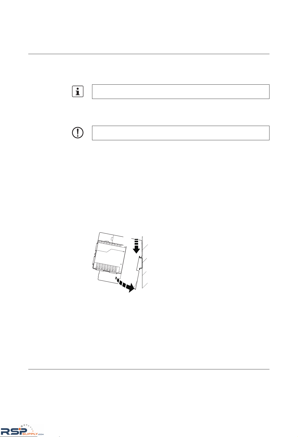
1. Place the module onto the DIN rail from above (A). The upper holding keyway must be
hooked onto the top edge of the rail. Push the module from the front towards the
mounting surface (B).
Figure 1-1 Snapping the head station onto the DIN rail
2. Once the module has been snapped on properly, check that it is fixed securely on the
rail. Check whether the positive latches are facing upwards, i.e., snapped on correctly.
Unless otherwise expressly stated, all information provided in this user manual always
applies to both the FL
SWITCH GHS 12G/8 and the FL SWITCH GHS 4G/12.
NOTE: Always switch off the supply voltage when mounting/removing the head station
and extension modules.
B
A
RSPSupply - 1-888-532-2706 - www.RSPSupply.com
http://www.RSPSupply.com/p-14161-Phoenix-Contact-2700271-FL-SWITCH-GHS-4G/12-Modular-Ethernet-Switch.aspx
Page 10
FL SWITCH GHS
1-2
PHOENIX CONTACT 8042_en_00
1.2 Mounting of the extension module
Mounting:
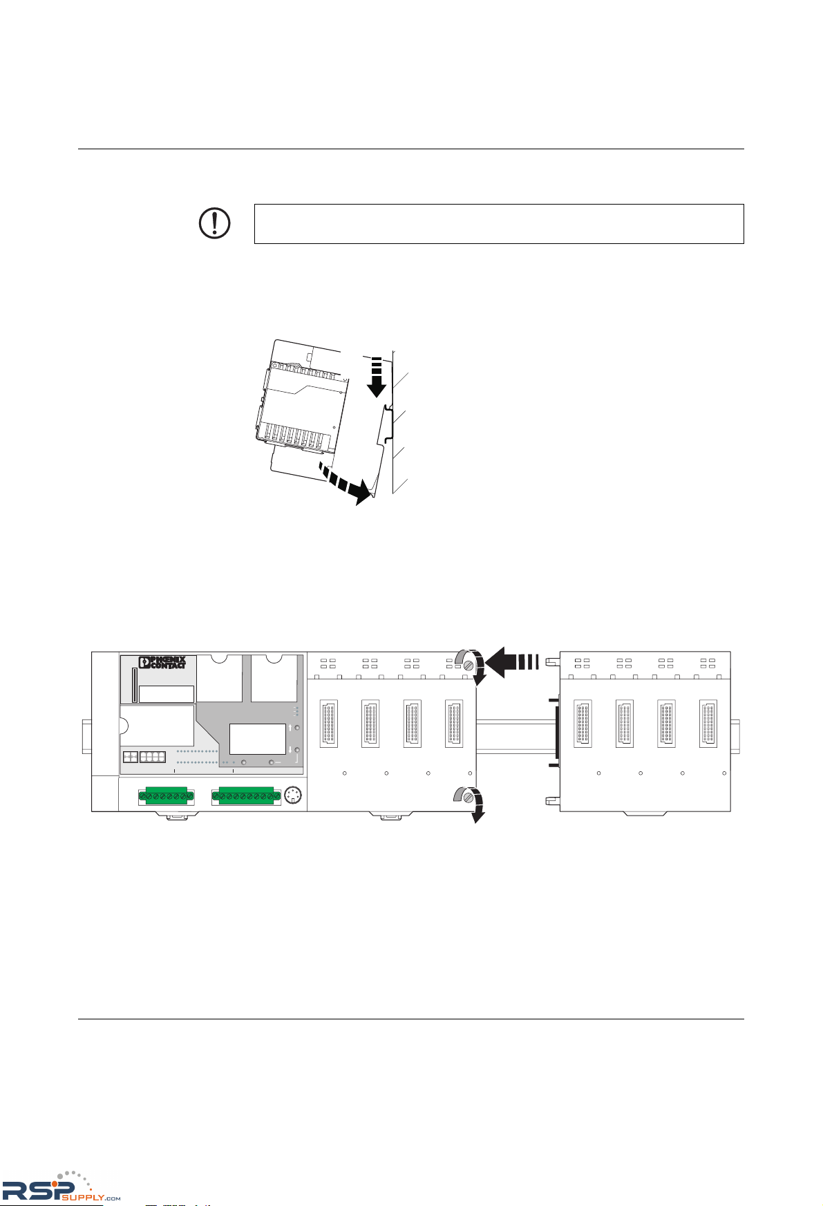
1. Place the module onto the DIN rail from above (A). The upper holding keyway must be
hooked onto the top edge of the rail. Push the module from the front towards the
mounting surface (B). Check that the positive latches have snapped on properly.
Figure 1-2 Mounting extension modules
2. Now that the extension module is snapped onto the DIN rail, push it along the DIN rail
towards the head station (A), until the male connector/female connector of the modules
are interlatched and the sides of the modules lie flush with one another. Secure the
connection using the two screws (B).
Figure 1-3 Mounting extension modules
NOTE: Always switch off the supply voltage when mounting/removing the extension
module.
B
A
MAC
Address
Ord.No.29 89 200
X29
MEM
FL SWITCH GHS 12G/8
X6X5X8X7X10X9X12
X11
X1
X3
X2
X4
X30 X31US1 UIGND
GNDI
GND DI2
MODE
LNK
X1
5
926
10
3711
4812
GNDI R2 R4 V.24
RESET
DI1
US1
US2
FAIL
DI2 UI
US2 DI1UI R1 R3 X32
A
B
B
RSPSupply - 1-888-532-2706 - www.RSPSupply.com
http://www.RSPSupply.com/p-14161-Phoenix-Contact-2700271-FL-SWITCH-GHS-4G/12-Modular-Ethernet-Switch.aspx
Page 11
Mounting and installing the Gigabit Modular Switch
8042_en_00 PHOENIX CONTACT 1-3
1.3 Installing the GHS
1.3.1 Connecting the supply voltage to the GHS
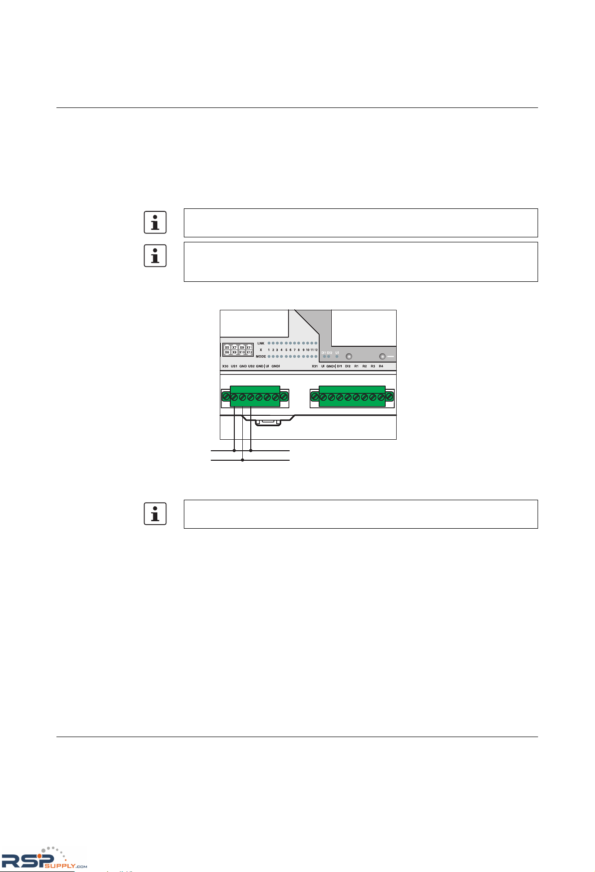
24 V DC The system is operated using a 24 V DC nominal voltage, which can be supplied from
separate power supply units if required.
1.3.1.1 Supplying the device from one voltage source
Figure 1-4 Supplying the system using one voltage source
Please refer to the UM EN FL SWITCH GHS user manual for information on how to
connect the redundant power supply, the sensor supply, and the alarm contacts.
If redundant supply voltage monitoring is active (default setting), an error is indicated if
only one voltage is applied. A jumper between US1 and US2 prevents this error message.
It is also possible to deactivate monitoring via the management interfaces.
Please refer to the UM EN FL SWITCH GHS user manual for information on how mount
and connect the interface modules as well as the SFP modules.
MAC
Address
Ord.No.2989 200
X29
MEM
FLSWITCH GHS 12G/8
X6X5X8X7X10X9X12
X11
X1
X3
X2
X4
X30 X31US1 UIGND
GNDI
GND DI2
MODE
LNK
X1
5
926
10
3711
4812
GNDI R2 R4 V.24
RESET
DI1
US1
US2
FAIL
DI2 UI
US2 DI1UI R1 R3 X32
US1
GND
RSPSupply - 1-888-532-2706 - www.RSPSupply.com
http://www.RSPSupply.com/p-14161-Phoenix-Contact-2700271-FL-SWITCH-GHS-4G/12-Modular-Ethernet-Switch.aspx
Page 12
FL SWITCH GHS
1-4
PHOENIX CONTACT 8042_en_00
1.4 Operability of the GHS
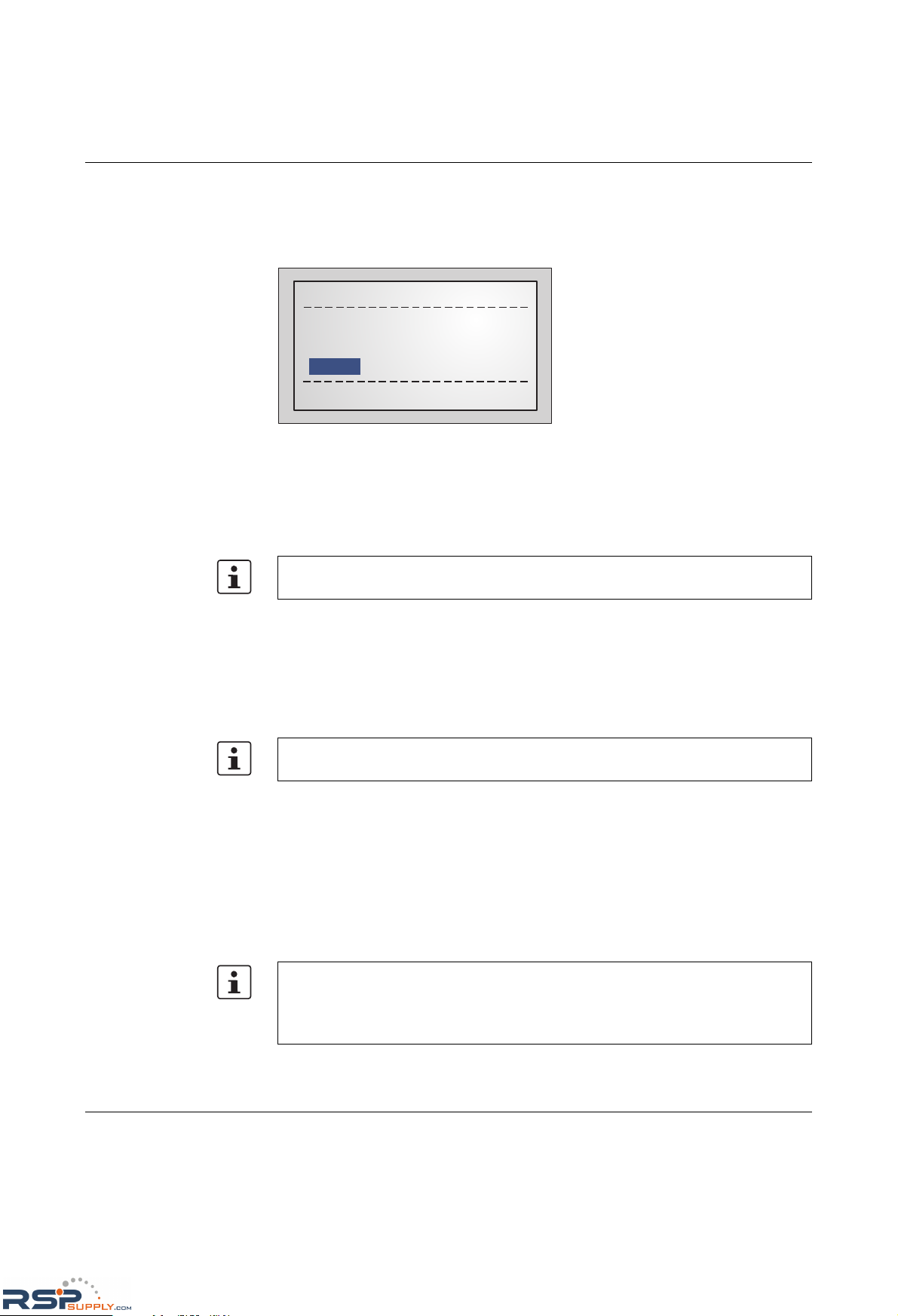
The device will boot automatically after you have connected the supply voltage. After a short
time the display will show the following:
Figure 1-5 Display after termination of the boot phase in default upon delivery
When the device is in the default upon delivery, it will send BootP requests. The GHS tries
to obtain IP addresses with these requests.
If your Switch displays something different, we recommend using the Smart Mode to reset
it to the default state upon delivery.
Before you can access the web-based management of the GHS, the device must be
assigned an IP address/IP parameters (see
"Assigning IP parameters" on page 1-5) or the
default IP address must be activated (see "Activating the default IP address" on page 1-4).
1.5 Activating the default IP address
After the boot phase, use the buttons/display to proceed as follows:
• Press "Menu".
• Select "IP Menu" and then press "Select".
• Select "IP Settings" and then press "Select".
• Select "Default IP" and then press "Set".
Now the Switch can be accessed with IP address: 192.168.0.100. You may have to adapt
your PC (see
"Making contact between the GHS and PC for initial configuration" on
page 1-7).
Please refer to the UM EN FL SWITCH GHS user manual for information on calling and
using the Smart Mode.
Please refer to the UM EN FL SWITCH GHS user manual for information on how to use
the display.
Please observe the following:
– The selection of the default IP is not saved retentively. Save the desired configuration
via the management interfaces.
– Make sure that there is only one device with the IP 192.168.0.100 in your network.
No IP assigned (01)
MENU
MODE
SPD FD
ACT
RSPSupply - 1-888-532-2706 - www.RSPSupply.com
http://www.RSPSupply.com/p-14161-Phoenix-Contact-2700271-FL-SWITCH-GHS-4G/12-Modular-Ethernet-Switch.aspx
Page 13
Mounting and installing the Gigabit Modular Switch
8042_en_00 PHOENIX CONTACT 1-5
1.6 Assigning IP parameters
The allocation of valid IP parameters is vital to the management function of the switch.
1.6.1 Assigning IP parameters with IPAssign
IPAssign is a free tool that does not require installation, but can be used to assign IP
parameters very easily using BootP. This tool can be found on the included CD or at
www.phoenixcontact.com.
Procedure
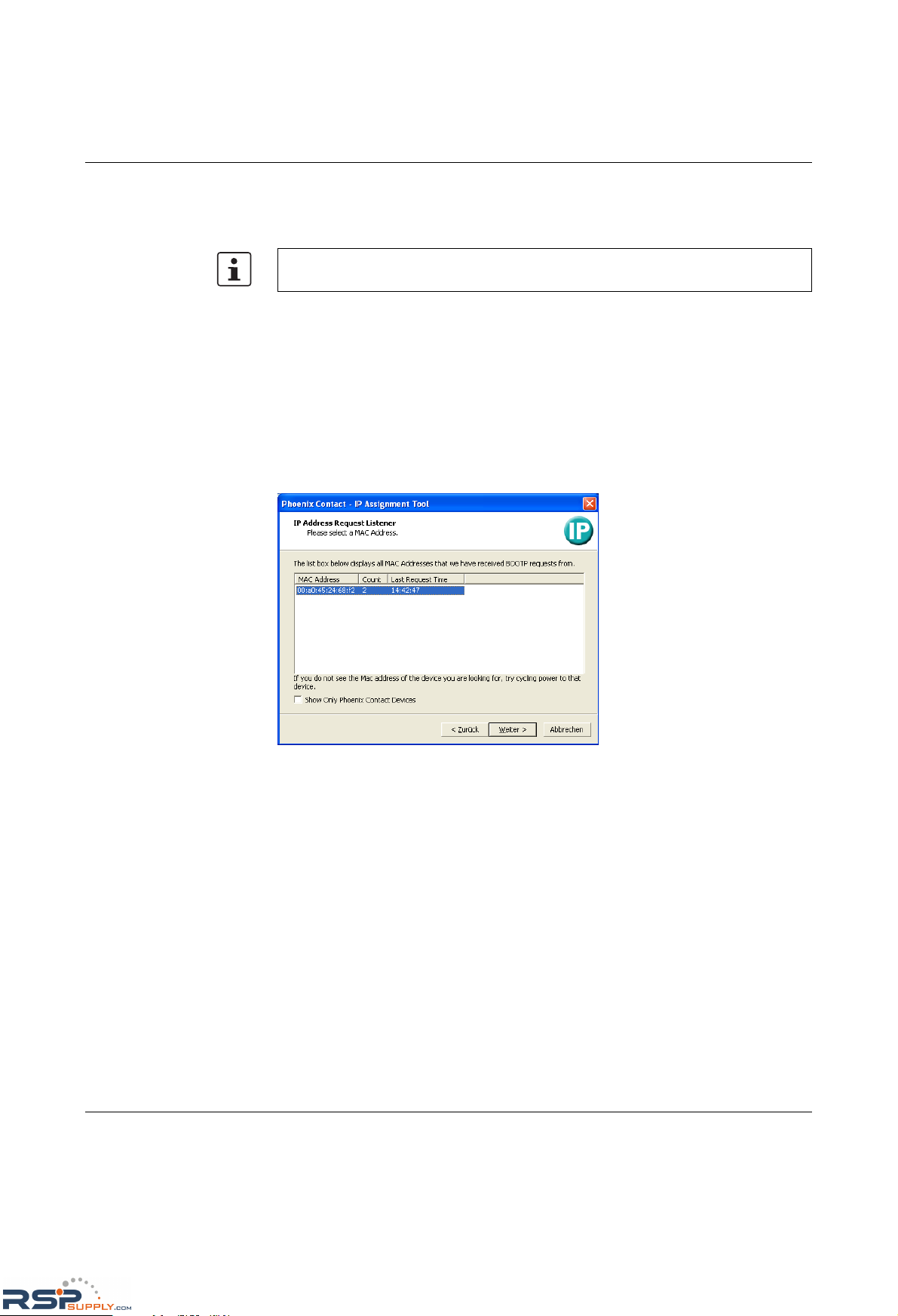
• Connect the switch to your PC and start IPAssign. The tool then displays the devices
that are sending BootP requests to assign an IP.
Figure 1-6 Devices sending BootP requests in IPAssign
If the switch has not been assigned valid IP parameters, "No IP assigned 01" will appear
in the display.
RSPSupply - 1-888-532-2706 - www.RSPSupply.com
http://www.RSPSupply.com/p-14161-Phoenix-Contact-2700271-FL-SWITCH-GHS-4G/12-Modular-Ethernet-Switch.aspx
Page 14
FL SWITCH GHS
1-6
PHOENIX CONTACT 8042_en_00
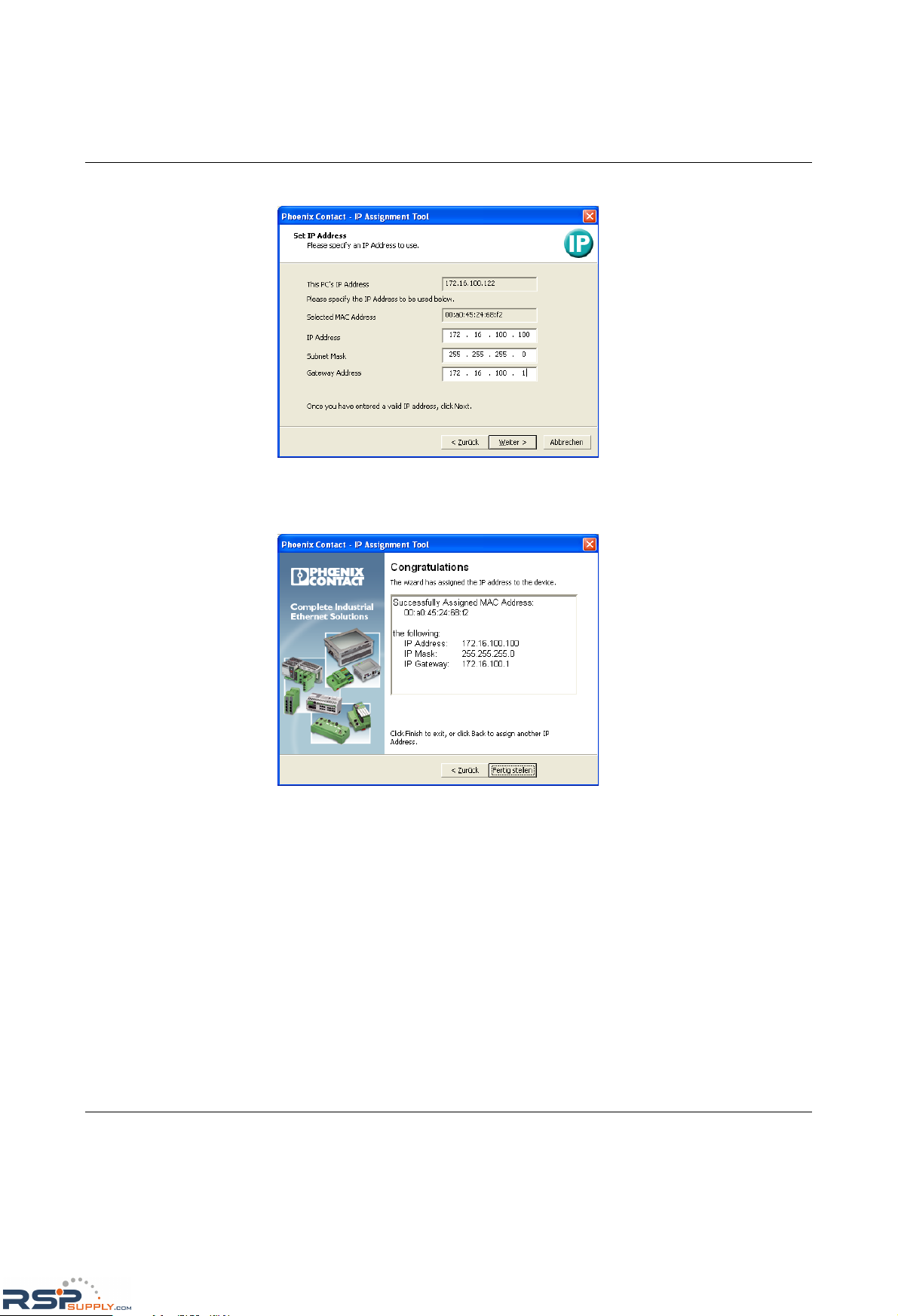
• Click "Next" and enter the desired IP parameters.
Figure 1-7 Mask for IP parameters
• Click "Next". If successful, this window is displayed.
Figure 1-8 Message in IPAssign
If you cannot access the web-based management of the GHS, you may have to adapt some
settings of your PC.
RSPSupply - 1-888-532-2706 - www.RSPSupply.com
http://www.RSPSupply.com/p-14161-Phoenix-Contact-2700271-FL-SWITCH-GHS-4G/12-Modular-Ethernet-Switch.aspx
Page 15
Mounting and installing the Gigabit Modular Switch
8042_en_00 PHOENIX CONTACT 1-7
1.7 Making contact between the GHS and PC for initial
configuration
1.7.1 Operation with static IP addresses
To enable the GHS to be accessed using the desired IP address, make sure that the
computer and the GHS are in the same IP subnetwork. In this case, for initial contact your
computer must be configured so that contact is possible. The following screenshots were
created under Windows XP Professional.
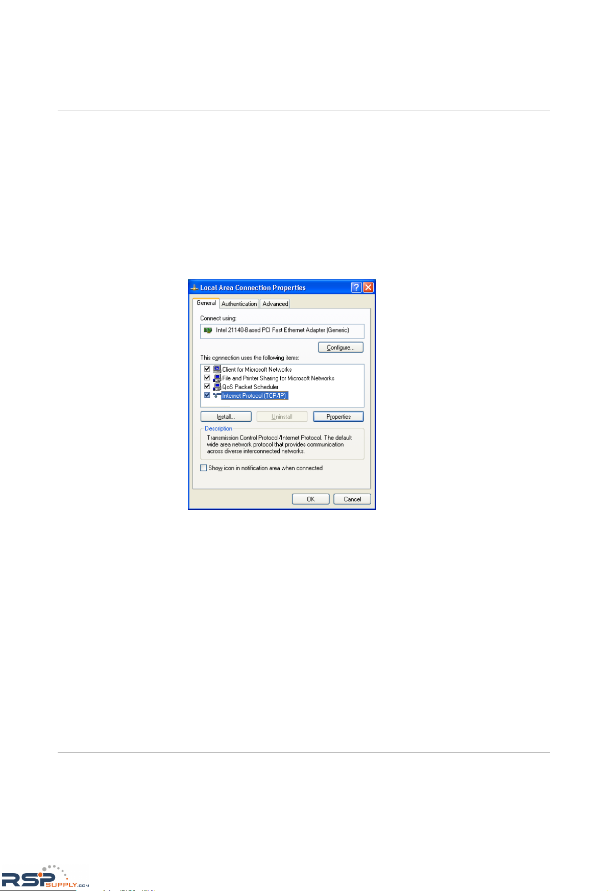
To set the IP parameters, open the Properties tab for your network adapter. Activate
"Internet Protocol (TCP/IP)" and then click on "Properties".
Figure 1-9 Properties dialog box for the network card
RSPSupply - 1-888-532-2706 - www.RSPSupply.com
http://www.RSPSupply.com/p-14161-Phoenix-Contact-2700271-FL-SWITCH-GHS-4G/12-Modular-Ethernet-Switch.aspx
Page 16
FL SWITCH GHS
1-8
PHOENIX CONTACT 8042_en_00
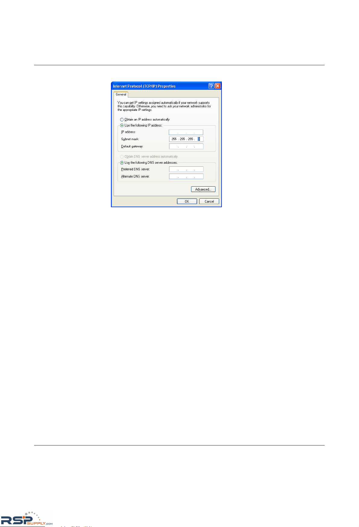
In the dialog box that opens, click on "Use the following IP address".
Figure 1-10 Internet Protocol Properties dialog box
Enter the desired IP address of your computer (not that of the GHS) in the "IP address" field
and the corresponding subnet mask. Close the dialog boxes with "OK".
The device can now be accessed via a web browser. In the address line of your browser,
enter the IP address of the GHS in the following format:
http://xxx.xxx.xxx.xxx
After entering the IP address in the browser, an overview page is displayed for the GHS
where no login is required.
After the correct user name and password have been entered the device configuration
pages are loaded.
1.7.2 Requirements for the use of WBM
As the web server operates using the Hyper Text Transfer Protocol, a standard browser can
be used. Access is via the URL "http://IP address of the device".
Example: "http://172.16.29.112".
For full operation of the web pages, the browser must support JavaScript 1.2 and cascading
style sheets Level 1. We recommend the use of Microsoft Internet Explorer 6.0.
RSPSupply - 1-888-532-2706 - www.RSPSupply.com
http://www.RSPSupply.com/p-14161-Phoenix-Contact-2700271-FL-SWITCH-GHS-4G/12-Modular-Ethernet-Switch.aspx
Page 17
Mounting and installing the Gigabit Modular Switch
8042_en_00 PHOENIX CONTACT 1-9
1.8 Web-based management
The user-friendly web-based management interface can be used to manage the switch from
anywhere in the network using a standard browser. To do this, http or https can be used,
this selection is made in the management interface. Comprehensive configuration and
diagnostic functions are clearly displayed on a graphic user interface. Every user with a
network connection to the device has read access to that device via a browser. Depending
on the physical structure of the switch, various information about the device, the set
parameters, and the operating state can be viewed.
You can now access the WBM of the GHS.
Modifications can only be made by entering the valid login details. By default upon
delivery, the user name is "admin" and the password is "private".
For security reasons, we recommend you enter a new, unique password.
Please refer to the UM EN FL SWITCH GHS user manual for information on how to use
the other management interfaces, (e.g., CLI, V.24).
RSPSupply - 1-888-532-2706 - www.RSPSupply.com
http://www.RSPSupply.com/p-14161-Phoenix-Contact-2700271-FL-SWITCH-GHS-4G/12-Modular-Ethernet-Switch.aspx
Page 18

FL SWITCH GHS
1-10
PHOENIX CONTACT 8042_en_00
RSPSupply - 1-888-532-2706 - www.RSPSupply.com
http://www.RSPSupply.com/p-14161-Phoenix-Contact-2700271-FL-SWITCH-GHS-4G/12-Modular-Ethernet-Switch.aspx
 Loading...