

Page 1

Page 2

Page 3
Please read this manual carefully before using the Phoenix Audio Technologies
MT700 - Stingray Distributed Array Mixer
Table of Contents
Introduction…....………………..…..…………………3
Product Overview.....………………..………………………4
Mixer Settings..................…………………………………..6
Dashboard Interface...…..…….….....……………………9
Mic Mixer Utility.........................….……………………..10
Line Mixer Utility.........................….……………………..12
SIP Client Setup..........……………………………..………14
Daisy Chaining and Zoning Concept……..………15
Warranty...................……………………………..………16
1
For additional help and updates, refer to our website www.phnxaudio.com
To contact Phoenix Audio for support, please send a detailed e-mail to support@phnxaudio.com
Page 4

Page 5
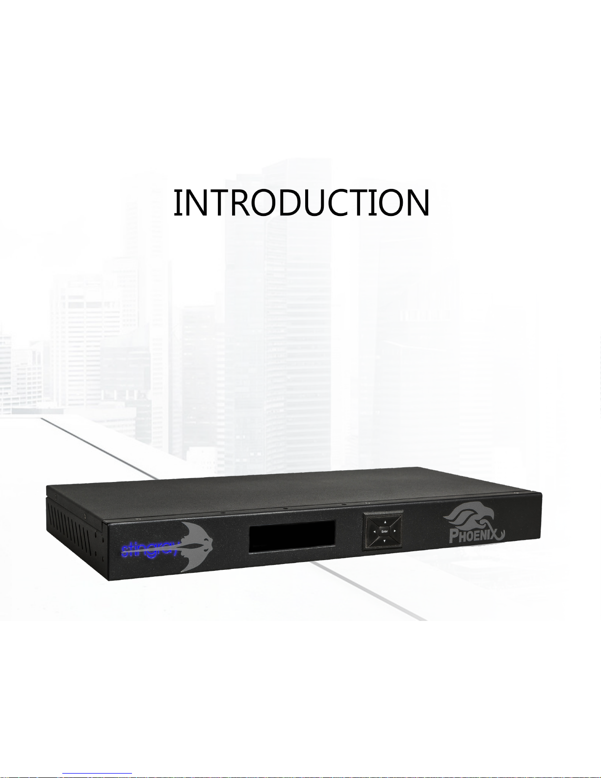
The Phoenix Audio Technologies - Stingray Distributed Array Mixer is an all-in-one smart mixer that uses
proprietary distributed array technology. The Stingray was designed to be a simple solution for the complex
needs of corporate and professional conferencing spaces. While focusing on this principle, we created a exible Distributed Array Mixer that can be a solution for any conferencing room setup. Even with the evolution
of variable number and size of conference rooms, the Stingray provides users with the ability to adapt to the
situation to create an environment where everyone can speak freely and naturally without compromising
audio quality.
Phoenix Audio Technologies believes that high quality audio should be easy to install and simple to use.
Users shouldn’t need to be audio experts to integrate or use our products. Our philosophy is that good
audio solutions should be complicated on the inside, so that they can be exible and simple solutions
that everyone can use. To perfect our craft, our company specializes in audio products for conferencing, which can be used either alone or to complement video solutions. We design and manufacture
products that address the fast pace changes in communication trends, conferencing environments, and
connectivity technologies.
3
Page 6
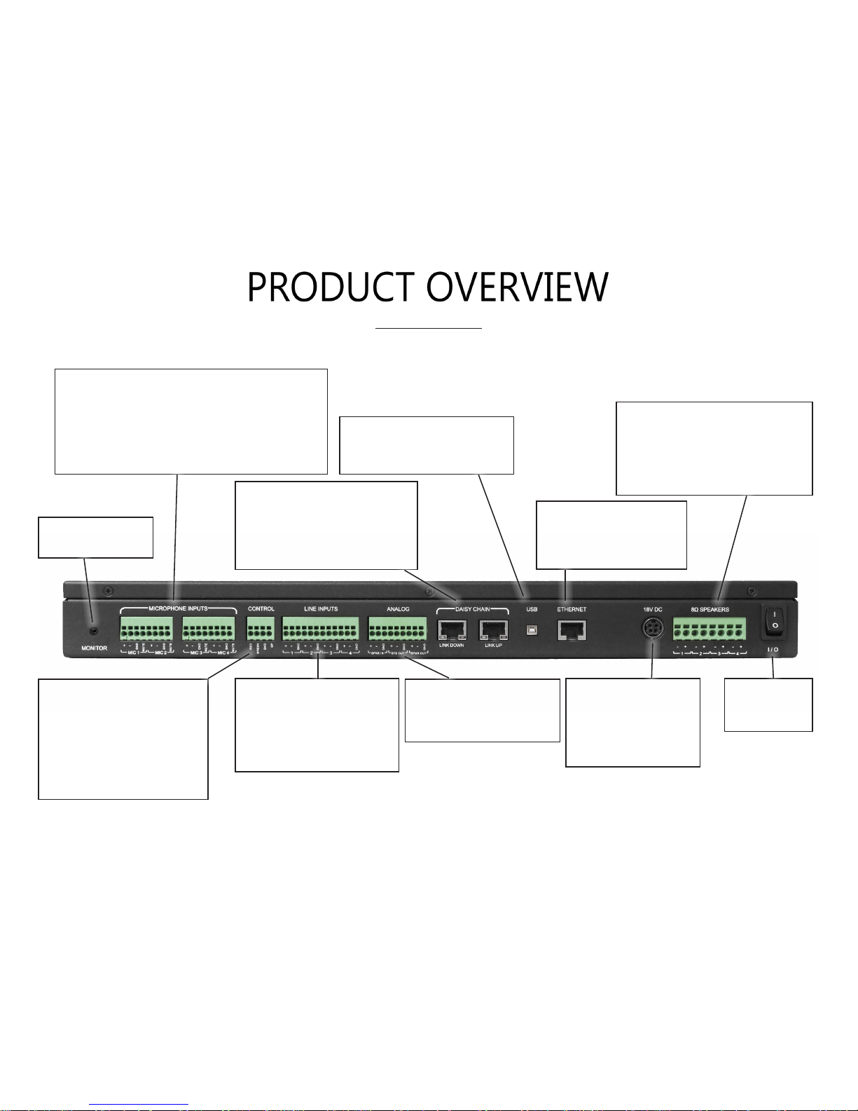
Specications
4
Four Microphone Level Inputs:
• Balanced
• 48V Phantom Power
• Gain: 14dB to 42dB in steps of 4 dB
• Separate mute request input: 10KΩ pull-up
resistor and should be short to GND to mute
Microphone Mute Control:
• Microphone mute request - Toggle initiated by
GND the input
• Three Output with logic
TTL. Can sink up to 200MA
to GND
Four Line Level Inputs:
• Balanced
• No Phantom
• Input level: 2V PTP
• Input Impedance: 20KΩ
Analog Input/Output:
• Balanced
• Line level: 2.3V PTP
Monitor Output:
3.5mm Audio Out
Daisy Chain - Link Up / Down:
• Proprietary Protocol
• Standard Cat 5/6/7 Cables
• Up to 15-Stingray units
• Data Only
Power:
• 110/220 through an
18V DC converter
• Each unit powered
separately
USB (Digital):
• Digital input to connect PC
• USB-B Connection
Ethernet - RJ45 Port:
SIP Interface connection
to be used with DTI.
Speaker Outputs:
• Balanced
• 8 Ω
• 15W / Channel can be used as
two pairs of stereo
Power Switch:
I - On
O - O
Page 7
5
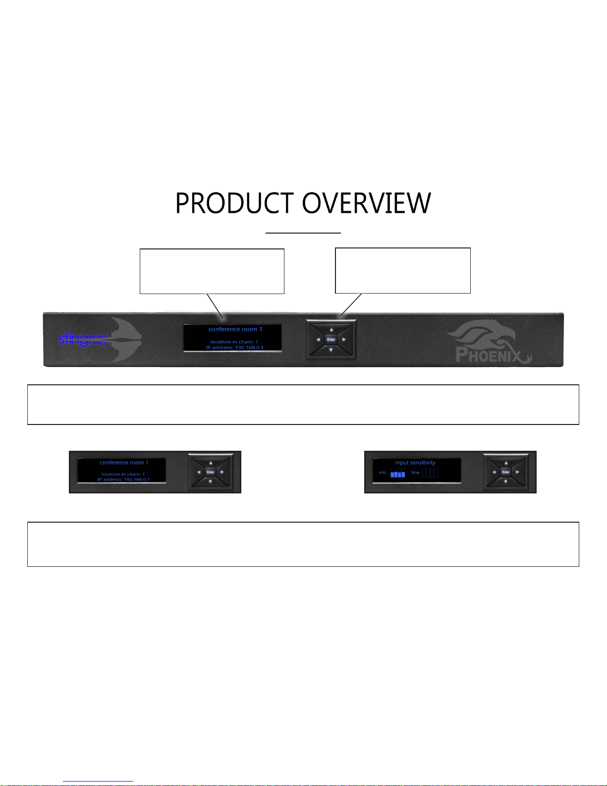
Specications
Directional Pad:
• Four-way directional buttons
with center button.
Power LED Screen:
• Options and setting menu
• Mixer and network information
The Stingray can be congured on the mixer using the directional pads and the menu
selections or through any browser on a device connected to the local network. In the following
pages, nd the options and settings that can be modied to t the needs of the conferencing space.
The LCD Screen displays the device name, the device chain location number and the local IP
address the device is connected. Using the directional keys will cycle the microphone and line out levels
screen and also the menu access screen. To access the menu screen, press the center “Enter” button.
Page 8

When accessing the menu, there will be seven selections which allow
the user to congure the mixer. In order to make the
selections, you can either press the center “Enter” key or the right di-
rection on the directional pad. To go back on the screen, press the left
direction to go back to the previous screen. The
selections and detailed descriptions are listed below.
1. primary/secondary selection
In order to select primary or secondary mixers within a daisy chain of Stingrays, you can identify the units within this menu selection. Note
that the primary mixer is the unit that is connected to the intended mode of communication (i.e. SIP, USB, or Analog) and when a specic
unit is selected as a primary, all units linked above in the daisy chain will be cut off from the unit. When the mixer is set to the primary mixer,
the connections to the intended mode of communications will turn on and the settings will be applied to all secondary units below. When
a mixer is set as a secondary unit, its connections to communication modes will be disabled and the settings will be inherited from the primary unit. Also if attempting to make a unit not connected to a daisy chain, an error message “can’t be set as secondary” will be prompted.
2. automatic mixer selection
Within this menu option, users will nd either the mixed microphone input or mixed line input options. When using mixed microphone input settings, the DSP will process and beamform the microphones inputs then add the line inputs. When using the
mixed line input option, the mixed microphone inputs will be disabled and the DSP processing will be dedicated to the line input.
3. microphone input setting
Users can control the microphone sensitivity within this menu as an entire group. There is a graphical representation of the ound levels the mixer detects from the microphone to better assist in adjusting the appropriate levels. Within
this menu, each microphone can be isolated and you can listen to the microphone that is highlighted on the LED Panel via
the monitor output or through the speaker outputs. The individual microphones can be selected with the directional pad.
6
Page 9

7
4. line input setting
The menu is congured with each line input channel with the option to mute, set as auxiliary or podium. The main difference between auxiliary or podium selection is that the auxiliary is used for outputs that do not pick up local sounds, which do not require
echo canceling. Podium mic function also has the capability to voice lift the user onto the local speakers.
5. speakers setting
The settings allow you to control the maximum output to the speakers with the master volume. Users can also balance the volume of audio inputs from USB or SIP from this menu.
6. general setting
Users can restore to factory default settings, set the display time out duration, and the display brightness.
When selecting the “restore factory default”, the user will be prompted with a message to ensure the intention of the reset.
The “display timeout” setting allows for durations of 30-second, 60-seconds (default), or 2-minutes.
For the “display brightness” setting, there are 6 levels of brightness available with the default set at the highest setting.
7. information
The information selection gives the programed settings in one location. The menu provides information if the Stingray is the
primary or secondary unit, mixed microphone or line input, current IP address, mac address, unit name, DSP version, SIP Version,
serial number and unit ID.
Page 10

The dashboard interface can be accessed from any browser on a device connected to the
local network, using the IP address displayed on the Stingray. It is recommended to use static IP addresses for Stingray units so it does not change. The dashboard gives the user remote access and control to the Stingray and allows for more setting options than directly on the device.
8
Device Setup:
Allows editing of the
settings of an individual
Stingray unit or any
number of units in daisy
chain.
SIP Client Setup:
Access controls to
conguration,
management, status
and diagnostics tabs
for Stingray units.
Menu:
Access Device/Chain
Setup or SIP Client
Setup via drop down
menu.
Quick Link to Phoenix
Audio Technologies
website.
www.phnxaudio.com
Page 11

9
On the “Device Setup” menu screen, users
will nd all Stingray mixers connected to the
primary IP address. You can select each individual device and modify the name of the
device, adjust primary and second settings
and edit the “Primary Parameters”.
Within the “Primary Parameters” selections,
users can adjust microphone sensitivity,
speaker Master Volume, input balance
levels, set individual line input volume balance and set them as podium or auxiliary.
Device Name
Page 12

10
Page 13

Mic Mixer Settings:
When using Mic Mixer selection, this allows the use of a total of four microphone
inputs and four line inputs. The four microphones inputs will have beam forming, noise
cancellation, echo cancellation, and automatic gain control applied and combined into a single
audio output. For this to function properly, all microphones being used must be the same model. In
the browser based dashboard interface, there are a number of different settings that can be adjusted.
Microphone Tab - Adjust microphone sensitivity for all microphones attached to the Stingray unit.
Adjuments will apply the sensitivity to all microphones as there is no individual sensitivity settings.
Speaker Tab - Adjust speaker output volume using the master volume slider tool which increases
overall volume. Users can adjust the balance of the speaker output of the USB, SIP, and Analog inputs
to create level sound. This is useful if multiple devices are bridged with different volume input levels.
Line Tabs - There are individual settings for each line input and users can set either “Podium” or “Auxiliary” for the inputs. If “Not Set” is selected, the line will not function. Hardware attached to the line
inputs will not have beam forming capabilities, but all other DSP processing will be applied.
The Podium setting input allows the users to make the input a priority speaker by allowing voice lift
which also broadcasts the user through the connected speakers. Users can also adjust the balance of
the local speakers, secondary levels, and the send out level. Noise Cancellation, echo cancellation, and
automatic gain control will be applied to this input.
The Auxiliary setting input allows the users to use the line for audio that does not require noise cancellation, echo cancellation, or automatic gain control. This is typically used for media like music, presentations with sound, or movie clips which allows the audio to be transmitted and output to the local speakers.
11
Page 14

12
Page 15

13
Line Mixer Settings:
When using Line Mixer selection, this disables the microphone inputs, reducing the number of inputs
to four. The Line Mixer settings will still receive noise cancellation, echo cancellation, and automatic
gain control applied to the audio. Like the Mic Mixer Setting, many of the adjustable eld are the same.
Speaker Tab - Adjust speaker output volume using the master volume slider tool which increases
overall volume. Users can adjust the balance of the speaker output of the USB, SIP, and Analog inputs
to create level sound.
Line Tabs - There are individual settings for each line input and users can set either “Podium”,
“Auxiliary” and “Mixer” for the inputs. If “Not Set” is selected, the line will not function. Hardware
attached to the line inputs will not have beam forming capabilities unless using the Mixer setting.
The Podium setting input allows the users to make the input a priority speaker by allowing voice lift
which also broadcasts the speaker through the connected speakers. Users can also adjust the balance
of the local speakers, secondary levels, and the send out level. Noise Cancellation, echo cancellation,
and automatic gain control will be applied to this input.
The Auxiliary setting input allows the users to use the line for audio that does not require noise cancellation, echo cancellation, or automatic gain control. This is typically used for media like music, presentations with sound, or movie clips which allows the audio to be transmitted and output to the local
speakers.
The Mixer setting allows users to beam form using the line input. In order for beam forming to work
properly, more than one line must be used and microphones must be the same model.
Page 16

When selecting “SIP Client Setup”, users will be prompted with a screen with Conguration, Management, and Status & Diagnostics tabs. You will nd the following settings under each menu.
Conguration:
-Quick Step
-Personal Settings
• Directory
• Speed Dial
• Tones
-Network Connections
• LAN Settings
-Voice Over IP
• Signaling Protocols
• Dialing
• Media Streaming
• Voice
• Line Settings
• Services
• Volume Settings
-Advanced Applications
•Date and Time
Management:
-Automatic Update
-Manual Update
• Conguration File
• Firmware Upgrade
-Administration
• Users
• Remote Control
• Restore Defaults
• Restart System
• Telnet
Status and Diagnostics:
-System Status
• Network Status
-History
• Call History
-System Information
• Versions
-Diagnostics
• Logging
• Recording
14
Page 17

The Stingray ability to adapt to variable conference room sizes through daisy chaining gives users the
capability to create multiple zones or combine the zones together to use all the hardware assets to
cover a large space. It is recommended all Stingray units are connected to a mode of communication
which allows the unit to become a primary unit. Illustrated below is the zoning concept which shows that
with ve units, you can either have ve seperate zones to one single large zone or any number inbetween
there with just a simple selection on our unit or any mechanical switch. This allows users to easily convert
their conference room sizes without the need to have an engineer rewire or recongure the equipment
that are already in place. This provides a solution that quickly and easily solves the changing spaces.
15
Page 18

In order to daisy chain Stingray units together, on the back panel will be two RJ45 ports marked “Link
Up” and “Link Down” under the daisy chain bracket. The “Link Down” port is used to connect a primary
unit to a secondary or a secondary to another secondary down the chain. The “Link Up” port is used
to connect to units above by connecting “Link Down” from the unit above to the secondary “Link Up”.
Connecting a secondary unit to the primary, the RJ45 cable will
leave the primary unit connected to “Link Down” and will connect into the secondary “Link Up” slot.
If the conference room setup requires to daisy chain more than
2 units, the third unit will connect to the secondary unit in the
chain with the RJ45 cable leaving the “Link Down” and connecting to the “Link Up” on the third unit.
Connecting additional units will follow the same procedures with a maximum of 15 Stingray units connected together (1 primary unit chained to 14 secondary units).
When changing one of the secondary units to a primary unit, the secondary units linked below the
new primary will now receive the settings from the new primary and the chain will seperate from
the units above the new primary unit. In order for a Stingray mixer to become a primary unit, it
must have connection to a mode of communication, either through USB, SIP or Analog connection.
To congure a Stingray mixer to a primary or secondary unit, it can be completed either directly on
the device (refer pg. 6), through the browser device dashboard (refer pg. 9) or a mechanical switch can
be congured to be used with the control port on the Stingray back panel.
*Recommend to use minimum CAT5 shielded cables with improved audio quality with CAT6 & CAT7 shielded cables.
16
Page 19

17
Zoning Notes
Unit set to Primary:
-Any unit can be congured to be a primary unit if it has a connection to a mode of communication
-Mode of communications will be turned on (USB, SIP, and Analog)
-Primary unit will dictate parameters to all secondary units below in the chain
-Daisy chain will be cut off at the next primary unit down the chain
-Podium and Auxiliary line channel features are enabled
Unit set to Secondary:
-Assume the settings of the primary unit
-Mode of communication connections are disabled
-Podium and Auxiliary line channel features are disabled, but ordinary line inputs function normally
*Note - A unit can have primary settings programed, but when switched to a secondary unit, the settings will be changed to the connected primary settings. The unit can switch to the primary unit at any
time and the unit will revert back to the programed primary settings as conguring a unit to secondary unitdoes not remove the primary settings of the unit.
Page 20

In order to obtain warranty coverage: (1) you must have proof of your properly-obtained limited warranty pursuant to Section 1 of this
limited warranty; (2) an excluded event must not have occurred with respect to the mechanical, electrical, or software defect, malfunction, or other failure in the product and/or its part(s); and (3) you must obtain a return authorization number and other return shipping
information from us to allow you to ship the product and/or part of the product back to us.
As part of these limited warranty services, we will offer (a) phone and e-mail support (see contact information in Section No. 6 below);
(b) free software upgrades for the purchased product, if applicable; and (c) no costs for any of the replacement parts or labor needed
to make the product function as warranted. No other services or repair work are included in this limited warranty other than the repairs
and services expressly described in this Section No. 4.
5. WHAT IS THE PERIOD OF COVERAGE?
This limited warranty begins on the date of your purchase of the product and lasts for two (2) years, subject to the requirements described in Section No. 1, subsections (a) through (c) of this limited warranty (the “Warranty Period”). The Warranty Period is not extended
if we repair or replace the product. We may change the availability of this limited warranty at our discretion, but any changes will not
cover periods before the chance went into effect.
6. HOW DO YOU OBTAIN LIMITED WARRANTY SERVICE?
To obtain limited warranty service, you must call (818) 937-4774 or email our Customer Service Department at support@phnxaudio.com
during the Warranty Period. No limited warranty service will be provided without satisfying the requirements described in Section No. 1,
subsections (a) through (c) of this limited warranty.
7. LIMITATION OF LIABILITY
EXCEPT FOR THE EXPRESS WARRANTIES CONTAINED IN THIS LIMITED WARRANTY STATEMENT, NO OTHER WARRANTY, EXPRESS OR
IMPLIED, INCLUDING WARRANTIES OF MERCHANTABILITY OR FITNESS FOR ANY PARTICULAR USE, APPLIES TO THE PRODUCT. THE
REMEDIES DESCRIBED ABOVE ARE YOUR SOLE AND EXCLUSIVE REMEDIES AND OUR ENTIRE LIABILITY FOR ANY BREACH OF THIS LIMITED WARRANTY. OUR LIABILITY SHALL UNDER NO CIRCUMSTANCES EXCEED THE ACTUAL AMOUNT PAID BY YOU FOR THE DEFECTIVE
PRODUCT, NOR SHALL WE UNDER ANY CIRCUMSTANCES BE LIABLE FOR ANY CONSEQUENTIAL, INCIDENTAL, SPECIAL OR PUNITIVE
DAMAGES OR LOSSES, WHETHER DIRECT OR INDIRECT. SOME STATES DO NOT ALLOW THE EXCLUSION OR LIMITATION OF INCIDENTAL OR CONSEQUENTIAL DAMAGES, SO THE ABOVE LIMITATION OR EXCLUSION MAY NOT APPLY TO YOU.
8. WHAT CAN YOU DO IN CASE OF A DISPUTE WITH US?
Any controversy or claim arising out of or relating in any way to this purchase or attempted purchase of this limited warranty
directly from us shall be brought on an individual, and not on a class actionbasis, shall be exclusively subject to binding
arbitration, which shall be administered by the American Arbitration Association, and decided by one (1) arbitrator, and
judgment upon the award rendered by the arbitrator may be entered in any court having jurisdiction thereof. By purchasing this limited
warranty, you further agree that the arbitrator, and not any federal, state, or local court or agency shall have exclusive authority to resolve any
controversies, claims, or other disputes arising out of or relating to the interpretation, applicability, enforceability or formation of this limited
warranty. By purchasing this limited warranty, you understand and agree that you are waiving and hereby waive your rights to maintain
other available resolution processes, such as a court action or administrative proceeding, to settle any disputes between you and us.
18
Page 21

19
THIS LIMITED WARRANTY GIVES YOU SPECIFIC LEGAL RIGHTS AND YOU MAY ALSO HAVE OTHER RIGHTS,
WHICH VARY FROM STATE TO STATE. THE LIMITED WARRANTY CAN ALSO BE FOUND ONLINE AT http://
www.phnxaudio.com/warranty/limitedwarranty.pdf OR IN THE DOCUMENTATION WE PROVIDE WITH
THE PRODUCT. WE WARRANT THAT DURING THE WARRANTY PERIOD, THE PRODUCT WILL BE FREE FROM
MECHANICAL, ELECTRICAL, AND SOFTWARE DEFECTS IN MATERIALS AND WORKMANSHIP. WE LIMIT
THE DURATION AND REMEDIES OF ALL IMPLIED WARRANTIES, INCLUDING WITHOUT LIMITATION THE
WARRANTIES OF MERCHANTABILITY AND FITNESS FOR A PARTICULAR PURPOSE TO THE DURATION
OF THIS EXPRESS LIMITED WARRANTY. SOME STATES DO NOT ALLOW LIMITATIONS ON HOW LONG AN
IMPLIED WARRANTY LASTS, SO THIS LIMITATION MAY NOT APPLY TO YOU. OUR RESPONSIBILITY FOR
THE DEFECTIVE PRODUCT IS LIMITED AS DESCRIBED BELOW IN THIS LIMITED WARRANTY STATEMENT.
1. WHO MAY USE THIS LIMITED WARRANTY?
Phoenix Audio Technologies, located at address 16 Goodyear Suite 120, Irvine, California 92618 (“we”, “us”, “our”, or its derivations) extends this
two (2) year limited product warranty (this “limited warranty”) only to the consumer who originally purchased the product to which this limited
warranty applies (“you”, “your”). It does not extend to any subsequent owner or other transferee of the product. It does not cover anyone not
located in the United States at the time coverage is sought under this limited warranty. To obtain coverage under this limited warranty, you must
(a) purchase the product which this limited warranty covers (and provide us with a sales receipt or other evidence acceptable to us showing
your purchase); (b) provide us with the serial number of the product for which you purchased the warranty; and (c) provide us with information
about you, if we request it. This limited warranty is expressly conditioned upon and valid only upon the satisfaction of the foregoing requirements of (a) through (c), and our receipt of any and all required payments in connection with the foregoing requirements of (a) through (c).
2. WHAT DOES THIS LIMITED WARRANTY COVER?
This limited warranty covers mechanical, electrical, or software defects in materials and workmanship of the product purchased by you from us (the
“product”) for the Warranty Period as dened below, and this limited warranty is specic to the product for which you purchased this limited warranty.
3. WHAT DOES THIS LIMITED WARRANTY NOT COVER?
This limited warranty does not cover any damage (“excluded events”) due to: (a) incidental events (e.g., coffee spills, water damage, damage re-
sulting from dropping the product, or re damage); (b) transportation; (c) storage; (d) improper use; (e) failure to follow the product instructions
or to perform any preventive maintenance; (f) modications; (g) unauthorized repair; (h) normal wear and tear; (i) misuse; ( j) external causes such
as accidents, abuse, or other actions or events beyond our reasonable control; or (k) damages or repairs that, in our opinion, result from similar
events. This limited warranty does not cover incidentals, general customer dissatisfaction (such as in the case of “buyer’s remorse”), lost peripherals
(e.g., misplaced cables or power supplies needed to use the product), or any damage not caused by a mechanical, electrical, or software defect.
4. WHAT WILL WE DO UNDER THIS LIMITED WARRANTY/WHAT ARE YOUR REMEDIES?
In the event of a mechanical, electrical, or software defect, malfunction, or other failure of the product not, in our opinion, the result of
excluded events, we will remedy the failure or defect without charge to you. We can choose to:
• Repair the product or defective, malfunctioning, otherwise failing parts in the product within a reasonable time as solely determined
by us; OR
• Replace the product or defective, malfunctioning, otherwise failing parts in the product within a reasonable time as solely determined
by us.
 Loading...