

Page 1
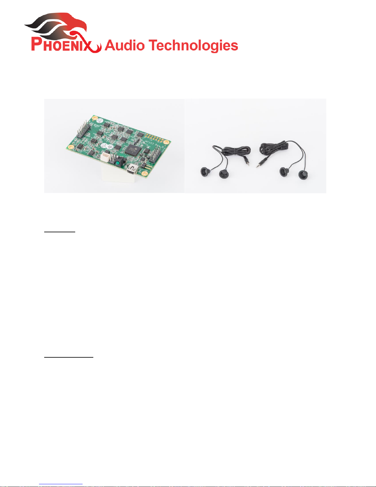
MT103KSK Four Microphone, Beamforming, & Echo
Canceling Kiosk Kit
The MT103KSK is a DSP based, four microphone, beamforming, stereo, and echo canceling
daughter board ideal for Kiosk solutions.
Features
The MT103KSK is a four microphone, beamforming, single output, stereo, 8KHz Noise Canceling/Echo Canceling
solution
The MT103KSK utilizes two, two-split Phoenix Audio microphones and your own loudspeaker. It provides both
analog and digital outputs
The 4 microphones are connected through a 0.1” pitch header. User can design the board to mount on its
motherboard with mating connector, or connect to the MT103KSK through wires
Controllable input level and phantom power supply via free downloadable utility
Analog output through a 0.1” pitch header. User can design the board to mount on its motherboard with
mating connector, or connect to the MT103-KSK through wires
Digital output through USB connection
Phoenix’s proprietary echo canceling, beamforming, noise canceling, and AGC algorithms with no gating, to
prevent the loss of critical information
Specifications
16KHz sampling frequency; 100Hz-8KHz bandwidth
Two levels of Echo Canceling aggressiveness and three levels of Echo Canceling speed
Controllable tail length – up to 200 ms.
Three levels of noise reduction: 8dB (Low), 14dB (Medium), and 20 dB (High), selectable through the free
control software
Residual noise suppressed to the environment noise level to prevent pumping noise
Phoenix Audio Technologies, 16 Goodyear Suite 120, Irvine, CA 92618; Tel (818) 937-4774
Fax (818) 859-1054
www.phnxaudio.com
Page 2

Eight preset color filters for both the output and the speaker signal
Low latency (10msec)
The 4 microphone inputs are connected to pins 1, 2, 3, & 4 of J1. The following microphone settings are
available using the setup software:
o Mic level (140mV peak-to-peak)
o Line level (2V peak-to-peak)
o Add 6dB boost
o Optional 2.8V power supply (phantom) , via 1 KOhm resistor
*Units are preset to Mic level without 6dB boost; Phantom On
Note: User has the option to use a single microphone connected to either pin 1, 2, 3, or 4 of J1. However, it is
recommended that the provided microphones are used and that all four are connected to maximize beamforming
and audio clarity.
o Far-End Inputs connected to USB and J1 pin 6. The input setting is Line level (2V peak-to-peak)
Notes:
1) Far-End Input will be received through the USB channel only.
System Output connected to the pin12 of J1 and USB. The following output settings are available using the
setup software:
o Line level: 2V peak-to-peak
o Mic level: 200mV peak-to-peak
*Units are preset to Line level
Note: Output will be transmitted through the USB and pin 12 of J1 and USB.
Speakers – (Far-end out signal) is connected to pin 11 and pin 13 of J1. The output setting is Line level: 2V
peak-to-peak
Phoenix Audio Technologies, 16 Goodyear Suite 120, Irvine, CA 92618; Tel (818) 937-4774
Fax (818) 859-1054
www.phnxaudio.com
Page 3
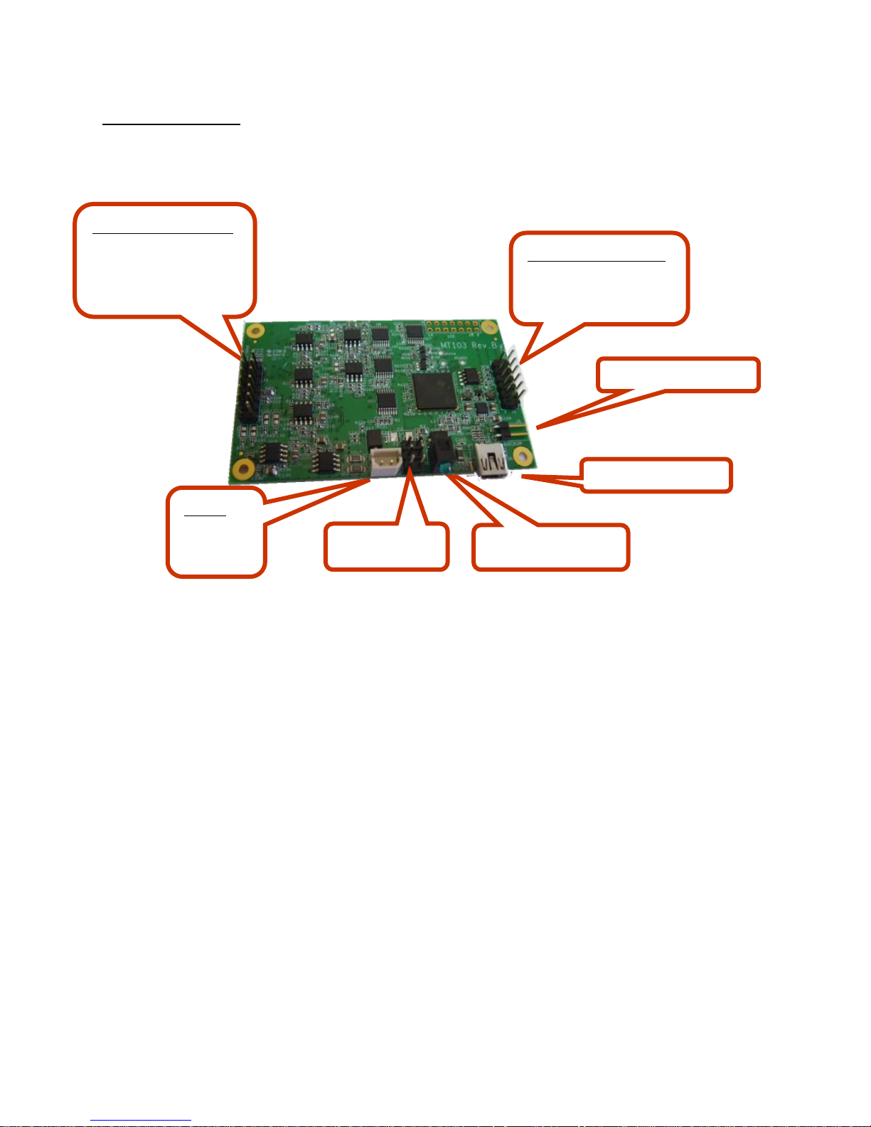
How to Connect:
Digital connector (J2)
Analog connector (J1)
Backup Reboot
USB
Power Indicator LED
Power
Alt Power (J6)
Microphone input
Far end inputs
Analog outputs
Reset
Shut Down
5V
DGND
Phoenix Audio Technologies, 16 Goodyear Suite 120, Irvine, CA 92618; Tel (818) 937-4774
Fax (818) 859-1054
www.phnxaudio.com
Page 4

Analog Connector (J1) Pin Definition
Pin
Name
Function
Level
Rating
1
IN1
Mic 1 In
Mic/Line
Mic = 140/280 mV ptp
Phantom 1K 2.8V
Line = 2/4V ptp
Input Impedance 24K
AC Coupled
Max Rating 4Vptp
2
IN2
Mic 2 In
Mic/Line
3
IN3
Mic 3in
Mic/Line
Mic = 140 mV ptp
Phantom 1K 2.8V
Line = 2 V ptp
Input Impedance 24K
AC Coupled
Max Rating 4Vptp
4
IN4
Mic 4 in
Mic/Line
5
IN5
NA Max Rating 4Vptp
6
IN6
Far-End In
Line = 2V ptp
7
3.3V
OUT
8
AGND
AGND
Input Amp Ground
9
AD0
10 bit A/D converter
AD0
Input level 0V-3V
Maximum Rating 4.5V
10
AGND
AGND
Output Amp Ground
11
OUT1
SPKL (FarEnd out)
line
Line = 2V ptp
12
OUT3
System Out
Line
Line = 2V ptp
13
OUT2
SPKR (FarEnd out)
Line
Line = 2V ptp
14
OUT4
N/A
N/A
N/A
Phoenix Audio Technologies, 16 Goodyear Suite 120, Irvine, CA 92618; Tel (818) 937-4774
Fax (818) 859-1054
www.phnxaudio.com
Page 5

Pin
I/O
Function
Notes
Nominal Rating
Max Rating
1 I N/A
Pulled Up – 100K
VIn Low<0.8V
Vin High>2V
0V – 4.5V
2 I N/A
Pulled Up – 100K
3 I N/A
Pulled Up – 100K
4 I N/A
Pulled Up – 100K
5 I N/A
Pulled Up – 100K
6 O SDA(I2C)
Pulled Up – 5K
VIn Low<1.0V
Vin High>2.3V
0V – 4.5V
7
I/O
SCL(I2C)
Pulled Up – 5K
VIn Low<1.0V
Vin High>2.3V
8 I
Shut Down
Active High,
Pulled Down
VIn Low<0.7V
Vin High>2.0V
0V – 5.0V
9 O N/A
Vout Low <0.4
Vout High >2.5
I Out
Max 4mA
10 O N/A 11 O N/A
12 I Reset
Active Low, Pulled
up 100K
VIn Low<0.7V
Vin High>2.0V
Pin
Function
Notes
Nominal Rating
Max Rating
1
Power GND
2
Vout
Connected to pin 4
4.75V-5.25V;
100 mAmp
0-7V
3
Vout Via 4.7Ohm
4
Vout
Connected to pin 2
4.75V-5.25V
100 mAmp
0-7V
5
NC 6
NC
GND connection recommendation
Improper GND connection can generate unwanted ground noise. In most cases we
recommend that you connect both analog grounds (pin 8 and 10) to your motherboard’s
power supply ground – and short the two as close as possible to the source (motherboard).
Digital Connector (J2) Pin Definition
Alternative Power Connector (J6) Pin Definition
Note: Pins 2 or 4 can be used as VIN to power the MT103, but the supply must be through
a Diode (0.5A)
Phoenix Audio Technologies, 16 Goodyear Suite 120, Irvine, CA 92618; Tel (818) 937-4774
Fax (818) 859-1054
www.phnxaudio.com
Page 6

Ideally 2in. (can be
between 1-3in)
Note: Horizontal
included
1in
Microphone Specifications & Set up
It is recommended that the four microphones delivered by Phoenix Audio are used in the setup for maximum quality.
The following is a guideline for placement and set up of the microphones to ensure the highest quality audio possible.
The microphones come with 3.5mm jacks and requires dismantling and consequential soldering/wiring to the pins.
(*It is advised that only trained engineers tend to such a task in order to ensure the quality of the final product)
If indeed you chose to use your own microphones, ensure that they have boots, and are identical in all aspects.
Place the microphones in the horizontal axis. (Do not place them vertically)
The spacing between the microphones should be 2in for optimal performance. However, they could be placed
1-3in apart. (Do not place closer than 1in apart)
Mount the microphone by drilling the holes onto the kiosk console or in a microphone box, and mount with
the microphone boots. (*ensure that the microphone enclosure has ample space and that the microphones
are facing the front of the kiosk, directly in front of where microphone input is received)
A cloth, foam cover, or grill should be placed in front of the microphones to reduce wind distractions and
increase pick up clarity
Layout. Plastic
Console not
Phoenix Audio Technologies, 16 Goodyear Suite 120, Irvine, CA 92618; Tel (818) 937-4774
Fax (818) 859-1054
www.phnxaudio.com
Page 7

Modifying System Parameters Through the SDK
As mentioned in the Specification section, some of the MT103KSK parameters can be controlled, modified, and
stored on the unit using a software setup utility which we refer to as the SDK.
The SDK is a graphic software utility, available for Windows operating systems that can be downloaded for free from
our website. The SDK communicates with the MT103KSK through a standard USB link.
Once the settings have been modified using the SDK, the user can save the new settings onto the device (by clicking
Save). The parameters that can be modified with the SDK include:
Input level (mic / line / 6dB boost)
Phantom power supply (yes / no)
Output level (mic / line).
Muting of any mic or speaker
These parameters can be controlled by “double clicking” the specific icon (for example the input amplifier) or
through the software’s menu.
Phoenix Audio Technologies, 16 Goodyear Suite 120, Irvine, CA 92618; Tel (818) 937-4774
Fax (818) 859-1054
www.phnxaudio.com
Page 8

MECHANICAL DRAWING IN DFX
For additional information please refer to our website at www.phnxaudio.com or contact us directly
Phoenix Audio Technologies, 16 Goodyear Suite 120, Irvine, CA 92618; Tel (818) 937-4774
Fax (818) 859-1054
www.phnxaudio.com
 Loading...