

Page 1

VX3-350-SCW-DAT
MASS STORAGE SUBSYSTEM
Technical Information
Copyright Phoenix International 1996. All Rights Reserved
812 W. Southern Avenue, Orange, CA 92865
Page 2

PREFACE
A number of conventions are used throughout this manual in order to provide clarity and
descriptive accuracy. These include:
1. The use of an 'H' (character) suffix to a number indicates that the number reference is in
hexadecimal notation.
2. The use of a '-' (minus) postfix to a signal name indicates that the signal is either true when the
signal is at a logic 0 level or that the signal initiates actions on a high-to-low signal transition.
DISCLAIMER
The information contained within this document has been carefully checked and is believed to be
entirely reliable and consistent with the product that it describes. However, no responsibility is assumed
for inaccuracies. Nor does Phoenix International assume any liability arising out of the application
or use of any product or circuit described herein. Phoenix International reserves the right to make
changes to any product and product documentation in an effort to improve performance, reliability or
design. Furthermore, the information contained herein is of a proprietary nature and is not to be
reproduced without prior written consent of Phoenix International.
TRADEMARKS
IBM, PC/XT, PC/AT, EGA, CGA, and VGA are registered trademarks of International Business
Machines Corporation. MS-DOS is a registered trademark of Microsoft Corporation. Hercules is a
trademark of Hercules Corporation.
REV 2.1
DATE 7-94
Page 3

Table of Contents
Chapter 1 Manual Organization and Introduction 1-1
Scope 1-3
Manual Organization 1-3
VX3-350-SCW-DAT Introduction 1-3
Chapter 2 Features and Specifications 2-1
Scope 2-3
Features 2-3
SCSI Interface Description 2-3
VX3-350-SCW-DAT Specifications 2-4
Chapter 3 Configuration, Installation, and Operation 3-1
Scope 3-3
Drive Hardware Configuration 3-3
Tape Hardware Configuration 3-3
Hard Drive Hardware Configuration 3-3
Considerations for Installation 3-3
VMEbus Slot Requirements 3-3
VMEbus Backplane Requirements 3-3
Power Supply Requirements 3-3
Installing the VX3-350-SCW-DAT 3-3
Drive Software Configuration 3-4
Tape Drive Software Configuration 3-4
Hard Drive Software Configuration 3-4
Termination 3-4
Terminator Power Configuration 3-4
DIFFSNS Voltage operation 3-4
Operation 3-4
Chapter 4 Hard Disk Drive Details 4-1
Scope 4-3
Introduction 4-3
Key Features 4-3
Physical Configuration 4-3
Drive Performance 4-3
Read/Write Performance 4-3
Power Requirements 4-4
Physical Characteristics 4-4
Environmental Characteristics 4-4
Reliability 4-4
Shock and Vibration 4-4
Functional Description 4-4
Error Correction 4-4
Option Jumpers 4-4
Power Connectors 4-4
SCSI Interface Connector 4-4
Page 4

Chapter 5 DAT Drive Details 5-1
Scope 5-3
Introduction 5-3
Key Features 5-3
Physical Configuration 5-3
Drive Performance 5-3
Power Requirements 5-3
Physical Characteristics 5-3
Environmental Characteristics 5-4
Reliability 5-4
Shock 5-4
Functional Description 5-4
Power Connector 5-4
Host Interface Connector 5-4
Chapter 6 Product Support, Service and Warranty 6-1
Scope 6-3
Warranty Statement 6-3
If You Have a Problem 6-3
Product Repairs 6-3
Obtaining an RMA 6-3
Shipping the Product 6-3
Providing a Product Defect Report 6-4
Warranty Repairs 6-4
Non-warranty Repairs 6-4
Product Updates 6-4
Tables
Figures
Table 2-2 SCSI Pin Definition 2-3
Table 2-3 P2 Pin Definition 2-5
Figure 1-1 VX3-350-SCW-DAT Front Panel 1-4
Figure 1-2 VX3-350-SCW-DAT Jumper Configuration 1-5
Page 5

Chapter 1
Manual Organization
and Introduction
Page 6

This page intentionally left blank.
Page 7

Scope
This chapter describes the organization of this manual and gives an overview of the VX3-350-SCW-DAT.
Manual Organization
This manual is organized as follows:
Chapter 1 MANUAL ORGANIZATION AND INTRODUCTION
Contains an overview of the manual organization and provides a brief product description.
Chapter 2 FEATURES AND SPECIFICATIONS
Describes the product features, compatibility, and electrical specifications.
Chapter 3 CONFIGURATION, INSTALLATION AND OPERATION
Provides information on how to configure and install the VX3-350-SCW-DAT.
Chapter 4 SCSI HARD DISK DETAILS
Contains specific details about the hard disk drive used on the VX3-350-SCW-DAT.
Chapter 5 DAT DRIVE DETAILS
Provides specific details about the tape drive used on the VX3-350-SCW-DAT.
Chapter 6 PRODUCT SUPPORT, SERVICE AND WARRANTY
Describes what to do if you have trouble and how we will support you.
VX3-350-SCW-DAT Introduction
The VX3-350-SCW-DAT has been designed to provide a complete disk/tape drive subsystem which is mechanically compatible with the VMEbus. It has been designed specifically to interface with VMEbus processors with an embedded SCSI
Host Adapter. Together with the processor, a complete system can be installed in only four standard VMEbus system
slots. The VX3-350-SCW-DAT provides a DAT drive and a hard disk drive within the same module making it very convenient to have fixed and removable data storage. The drives used on board the VX3-350-SCW-DAT were chosen for their
compatibility, ruggedness and reliability.
Manual Organization and Introduction 1-3
Page 8
HD
S
C
S
I
2
1 3
0 4
7 6
6
UNIT 0
ID
2
1 3
0 4
7 6
6
UNIT
ID
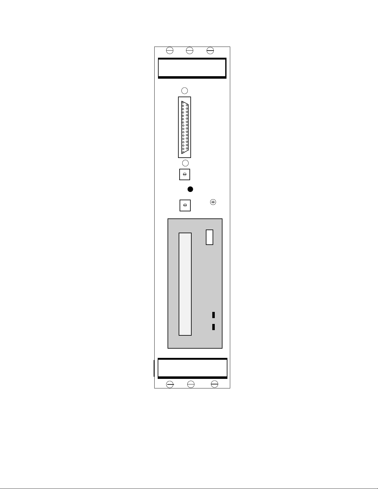
Figure 1-1: VX3-350-SCW-DAT Front Panel
VX3-350-SCW-DAT User's Manual1-4
Page 9

DAT Drive
Fixed Hard Drive
Figure 1-2: VX3-350-SCW-DAT Jumper Configuration
Manual Organization and Introduction 1--5
Page 10

Chapter 2
Features and
Specifications
Page 11

This page intentionally left blank.
Page 12

Scope
This chapter describes the overall features and specifications of the VX3-350-SCW-DAT.
Features
The VX3-350-SCW-DAT incorporates a very compact winchester disk drive and a DDS-4 DAT drive within a single
module. The tape drive is physically compact, occupying only 3 1/2” of panel in the half-height form factor. The hard
disk drive is a high-performance winchester type with embedded disk drive control electronics. This embedded controller is on the hard disk and the tape drive are microprocessor controlled and compatible with ANSI X3.131-1986
SCSI commands. The hard drive is a very high performer, with an average track-to-track access times of less than 6
milliseconds. It incorporates at least an embedded 2 Mbyte buffer which is operated in “look ahead” mode, providing
buffering for sequential sector operations. The tape drive is DDS-4 compatible. Both the hard drive and the tape drive
have been carefully packaged with suitable control cables and power distribution connectors for direct attachment to
single board computers in the VME chassis or to external devices.
SCSI Interface Description
In order to provide a method of embedding the disk drive control electronics within the hard disk drive, several disk
drive manufacturers jointly defined an interface specification. This specification for the
face
has become known throughout the industry as “SCSI”. Basically, the SCSI interface consists of the required
address, data and control signals from an SCSI Host Adapter. Since a goal of the specification is to allow the disk drive
to be connected via standard cable, the specification required buffering of all signals so that the drive could be mounted
a suitable distance from the board interface. This distance, however, is limited to 12 meters. The specification provides all signals via a 68 pin header connector for use with standard 68 conductor cable and connectors. Table 2-2 is a
description of the Ultra-160 SCSI pin definition. The direction indicated is relative to the host(IN=From Host/Out=To
Host).
Pin Signal Direction Description Pin Signal
1 +DB (12) In/Out Bidirectional data line 12 35 -DB(12)
2 +DB (13) In/Out Bidirectional data line 13 36 -DB(13)
3 +DB (14) In/Out Bidirectional data line 14 37 -DB(14)
4 +DB (15) In/Out Bidirectional data line 15 38 -DB(15)
5 +DB (P1) In/Out Bidirectional data line P1 39 -DB(P1)
6 +DB (0) In/Out Bidirectional data line 0 40 -DB(0)
7 +DB (1) In/Out Bidirectional data line 1 41 -DB(1)
8 +DB (2) In/Out Bidirectional data line 2 42 -DB(2)
9 +DB (3) In/Out Bidirectional data line 3 43 -DB(3)
10 +DB (4) In/Out Bidirectional data line 4 44 -DB(4)
11 +DB (5) In/Out Bidirectional data line 5 45 -DB(5)
12 +DB (6) In/Out Bidirectional data line 6 46 -DB(6)
13 +DB (7) In/Out Bidirectional data line 7 47 -DB(7)
14 +DB (P) In/Out Bidirectional data line P 48 -DB(P)
15 GND - Ground reference 49 GND
16 DIFFSNS (1) - 50 GND
17 TERMPWR - Terminator Power 51 TERMPWR
18 TERMPWR - Terminator Power 52 TERMPWR
19 RESERVED - Reserved for future use 53 RESERVED
20 GND - Ground reference 54 GND
21 +ATN In/Out Attention 55 -ATN
22 GND - Ground reference 56 GND
23 +BSY In/Out Busy 57 -BSY
24 +ACK - In Acknowledge 58 -ACK
25 +RST In Reset 59 -RST
26 +MSG Out Message 60 -MSG
27 +SEL In/Out Select 61 -SEL
28 +C/D Out Control/Data 62 -C/D
29 +REQ Out Request 63 -REQ
30 +I/O Out Input/Output 64 -I/O
31 +DB (8) In/Out Bidirectional data line 8 65 -DB(8)
32 +DB (9) In/Out Bidirectional data line 9 66 -DB(9)
33 +DB (10) In/Out Bidirectional data line 10 67 -DB(10)
34 +DB (11) In/Out Bidirectional data line 11 38 -DB(11)
Table 2-2: SCSI Pin Definition
NOTES:
(1) The DIFFSNS voltage level determines single-ended or LVD operation.
(2) The minus sign next to the signals indicates active low, plus indicates active high.
Small Computer System Inter-
Features and Specifications 2-3
Page 13

VX3-350-SCW-DAT Specifications
The following table provides the specifications of the complete VX3-350-SCW-DAT. Individual disk/DAT drive specifications are given in their respective chapters.
General
Model: VX3-350-SCW-DAT
Description: Hard disk/DAT drive module compatible with LVD/SE SCSI commands.
Interface: DAT drive: LVD/SE Ultra-160 SCSI
Hard Drive: LVD/SE Ultra-160 SCSI
Drive Type: Tape drive:..Digital Audio Tape drive
Hard Drive: (depends on capacity ordered)
Hardware Compatibility:VMEbus Double Eurocard (6Ux12HP)
Electrical
Power: +5VDC .200A(max)
+12VDC (applicable to mounted device only)
Power figures are with both drives R/W
Physical
Size: 160mm x 234mm (Double Eurocard)
12HP (3 Standard Slots)
Construction: Steel/Double-sided Printed Circuit
Environmental
Temperature: 0-55oC Inlet Air (Operating)
-20oto 60oC (Non-operating)
Humidity: 8-80% RH, Non-condensing
Shock: Unit will withstand shock exceeding the specifications of
devices mounted.
Features and Specifications2-4
Page 14

P2 Connector Pin Definitions
P2 Pin Row A Signal P2 Pin Row C Signal
1 -DB0 1 +DB0
2 -DB1 2 +DB1
3 -DB2 3 +DB2
4 -DB3 4 +DB3
5 -DB4 5 +DB4
6 -DB5 6 +DB5
7 -DB6 - 7 +DB6
8 -DB7 8 +DB7
9 -DBP 9 -DB8
10 +DBP 10 -DB9
11 +ATN 11 -DB10
12 +SBSY 12 -DB11
13 +SACK 13 -DB12
14 +SRST 14 -DB13
15 +SMSG 15 -DB14
16 -ATN 16 -DB15
17 GROUND 17 -DBP1
18 -BSY 18 TERMPWR
19 -ACK 19 +DB8
20 -RST 20 +DB9
21 -MSG 21 +DB10
22 -SEL 22 +DB11
23 -C/D 23 +DB12
24 -REQ 24 +DB13
25 -IO 25 +DB14
26 26 +DB15
27 27 +DBP1
28 28 +SEL
29 DIFFSNS 29 +C/D
30 30 +REQ
31 31 +I/O
32 32 P2ONL
Table 2-3 P2 Pin Definitions
Features and Specifications 2-5
Page 15

Chapter 3
Configuration, Installation,
and Operation
Page 16

This page intentionally left blank.
Page 17

Scope
This chapter describes how to configure, install and operate the VX3-350-SCW-DAT mass storage subsystem module.
DAT Drive Hardware Configuration
The DAT drive can be set so that it is activated by the SCSI unit 0-F, as is required to maintain compatibility with the SCSI
software. The drive installed on the VX3-350-SCW-DAT utilizes the Ultra-160 SCSI interface. It is possible to connect
another type of SCSI device via the interface cable and to connect 14 other units to the SCSI interface if needed. Please
call Phoenix International Customer Support if you need assistance.
Hard Disk Drive Hardware Configuration
The hard drive can be set so that it is activated by the SCSI unit 0-F, as is required to maintain compatibility with the SCSI
software. The hard drive installed on the VX3-350-SCW-DAT utilizes the Ultra-160 SCSI interface. It is possible to connect another type of SCSI device via the interface cable and to connect 14 other units to the SCSI interface if needed.
Please call Phoenix International Customer Support if you need assistance.
Considerations For Installation
There are several considerations before installing the VX3-350-SCW-DAT into your system.
VMEbus Slot Requirements
The VX3-350-SCW-DAT requires three adjacent slots in a standard VMEbus 6U card cage. Since the drives are mounted on an steel panel, this could potentially cause a shorting problem. If you are going to have a VMEbus card located in
the next adjacent slot, you should carefully check it to make sure that no leads are likely to touch the VX3-350-SCW-DAT.
VMEbus Backplane Configuration
The VMEbus P1 connectors supply all operating power to the VX3-350-SCW-DAT and shunts the daisy-chain signals on
the P1 connectors. However, no other VME signals are connected on board. Therefore, you must check your VMEbus
backplane for all daisy-chain signals continuity at the two slot positions occupied by the VX3-350-SCW-DAT.
Power Supply Requirements
Make sure that your VMEbus power supply has adequate capabilities to support the operation of the VX3-350-SCW-DAT
when it is installed with all other cards in your VMEbus system. Pay particular attention to the +12 volt power requirement. The specifications listed in Chapter 2 should be consulted for the maximum current requirements. Your power
supply must be capable of providing sufficient current for the hard disk drive motor to spin up during initial operation
(approximately 5 seconds).
Installing the VX3-350-SCW-DAT
Make sure that all power is removed from the backplane before inserting the boards. Prior to inserting the VX3-350SCW-DAT into the card cage, it is necessary to verify the cable connections to the SCSI host/processor. Once you have
connected and properly seated the associated cable assemblies, you should insert the host/processor into the VMEbus
card cage. Now install the VX3-350-SCW-DAT into the VME chassis and mate the P1 connector properly. The P2 connector should also be aligned. Then connect the VX3-350-SCW-DAT to the SCSI host/processor with a 68 pin Micro-D
cable or via the P2 connector on the backplane with the proper Phoenix International adapter module.
Configuration, Installation, and Operation 3-3
Page 18

Drive Software Configuration
Initially you will need to run a device setup program in order to configure the software and hardware to properly recognize
the drives on the VX3-350-SCW-DAT. You should consult the host/processor manual and/or operating system manuals
for a description of the utility required to properly format and use your mass storage subsystem.
DAT Drive Software Configuration
The DAT drive can be installed as SCSI unit 0-15 (F). It has a formatted compressed storage capacity of up to 40 Gigabytes. You can assign the logical unit designation from the SCSI setup utility.
Hard Drive Software Configuration
The hard disk drive can be installed as SCSI unit 0-15(F). The disk drive characteristics are described in detail in Chapter
4. It operates using the Ultra-160 SCSI interface and has to be configured by the host operating system software for
proper operation.
Termination
The Multimode termination required for the LVD/SE SCSI-3 bus is on the VX3 module. The SensiTermTMcircuitry will
automatically configure the termination for the SCSI bus. It determines if the SCSI bus signals are received from the P2
connector or from the Micro-D connector on the front panel and sets the termination at the correct end of the SCSI bus. If
the module is in the middle of a SCSI bus route, the SensiTermTMcircuitry automatically disables all on board termination.
DIFFSNS Signal
The voltage level of the DIFSNS signal determines if the drives will run in a Single Ended SCSI configuration or a Low
Voltage Differential configuration. With a DIFFSNS voltage level of 0 Volts (Ground), the unit will terminate the bus in the
Single Ended SCSI mode. If the DIFFSNS line can be driven to 1.3 volts, indicating that the Host adapter is LVD capable,
the bus will be terminated in the Low Voltage Differential mode. If any SCSI unit attached to the bus is only Single Ended
SCSI capable, the bus will terminate in the Single Ended mode.
Terminator Power
Terminator power for the drives is routed from the front panel uD68 pin connector to the termination circuitry and to the P2
connector, Pin C18. The Terminator power has to be generated at the SCSI Host adapter.
Operation
Once the VX3-350-SCW-DAT has been configured properly and the software has been set up, operation is identical to
that of a standard SCSI storage subsystem. No specialized software is required.
Configuration, Installation, and Operation3-4
Page 19

Chapter 5
SDT 11000 DAT Drive
Details
Page 20

Scope
This chapter describes the SONY SDT 11000 DAT drive in detail.
Introduction
The SDT 11000 is a high performance 3.5" low profile 40 Gigabyte (compressed) DAT drive that is designed to
operate with a SCSI host adapter or equivalent. The drive features low power requirements enabling operation
in portable environments. The drive uses the industry standard Small Computer System Interface (SCSI-2).
Key Features
• Low power requirements enabling operation in portable applications
• Typical streaming transfer rate of 4.7 Mbytes/second.
• 10 Mbyte data buffer
• Automatic error detection and correction
• Read-after-write error detection and correction
• Synchronous and asynchronous communication modes
• Embedded Wide Ultra LVD/SE SCSI connection
• No operator maintenance: incorporates Sony's patented Super Head Cleaner
TM
technology
• Supportted formats: DDS-4, DDS-3, DDS-2, DDS, DDS-DC and DCLZ
Physical Configuration
Bytes per Block: Variable or fixed
Formatted Capacity: Up to 40 gigabytes(compressed mode)
Drive Interface: Wide Ultra LVD/SE SCSI
Cache Buffer Size: 10 Mbyte
Drive Performance
Move to Start: 3.5 seconds
Change direction: 2.1 seconds
Write (full reposition) 4.2 seconds
Max rewind to BOP: Less than 55 seconds
External Transfer Rate: 10 Mbyte/sec (synchronous)
SDT 11000 DAT Disk Drive Details 5-3
Page 21

Power Requirements
+ 12 Volt Start-up: 0.75 Amps
+ 12 Volt Typical: 0.25 Amps
+ 5 Volt Typical: 1.00 Amps
Typical Usage: 8.0 Watts
Physical Characteristics
Height: 1.625 inches
Length: 5.75 inches
Width: 4.00 inches
Weight: 1.41 pounds, without cartridge
Environmental Characteristics
Temperature: 5º C to 40º C (operating)
Thermal Gradient: 10º C per hour maximum
Humidity: 20% to 80% RH, non-condensing
Altitude: 0 to 15,000 feet (operating)
Reliability
-40º C to +70º C (non operating)
0 to 50,000 feet (non-operating)
MTBF: 250,000 hours (POH)
MTTR: 10 minutes (typical)
Shock and Vibration
Shock: 5 G's (operating)
maximum duration of 3 msec (half sinewave)
90 G's (non-operating)
maximum duration of 11 msec (half sinewave)
Vibration: 5-500 Hz @ 0.25 G (operating)
5-22 Hz @ 0.040 inches
22-400 Hz @ 2.00 G's
Functional Description
The SDT 11000 contains all necessary mechanical and electronic parts to interpret control signals, position the
recording heads over the desired track, read and write data, and provide a contaminant free environment for the
heads and disks.
Power Connector
The SDT 11000 has a 4 pin DC power connector equivalent to that of a standard disk drive. It uses a mating
connector, AMP 1-480424-0 with AMP 350078-4 pins.
Functional Description
The SDT 11000 has a 68 pin SCSI connector. Two drives or other SCSI devices may be daisy chained together
with a maximum cable length of 18 feet, by using the SCSI connector on the front panel of the VX3-350-SCWDAT Mass Storage Subsystem.
5-4 SDT11000 DAT Drive Details
Page 22

Chapter 6
Product Support,
Service and Warranty
Page 23

This page intentionally left blank.
Page 24

Scope
This chapter describes Phoenix International’s product support program. It states our product warranty and provides
details about what to do if you have a problem with the product.
Warranty Statement
Phoenix International VMEbus products come with a “return-to-factory” warranty which covers defects in materials and
workmanship for a period of seven years from the date of product shipment to the customer, provided the product is
unmodified and has been subject to normal and proper use. Warranty on non-Phoenix International manufactured
devices incorporated into Phoenix VMEbus products is restricted to that provided by their manufacturer only.
If You Have a Problem
If you are having a problem with a Phoenix International product, you should call our main number, (714) 283-4800, and
ask for Customer Service. Please be prepared to supply as much detail as you can concerning the nature of the problem
and the conditions in which the problem appeared.
Obtaining an RMA
In order to return the product for repair, the following steps are necessary:
1. Obtain a return materials authorization number (RMA#)
from Phoenix International Customer Service.
2. Ship the product prepaid to the designated repair point.
3. Provide with the product a written description ofthe
claimed defect.
Shipping the Product
Any product returned to Phoenix International should be in its original shipping carton if possible. Otherwise the product
should be carefully packaged in a conductive packing material and placed in a cushioned corrugated carton suitable for
shipping. Please mark the shipping label with the RMA number and return it to:
Phoenix International
812 W. Southern Avenue
Orange, CA., 92865
Attn: Customer Service Department
RMA #: ___________
Product Support, Service and Warranty 6-3
Page 25

Providing a Product Defect Report
When you are returning a product for repair, it is very important to include a written report which details the nature of the
problem in order to expedite the repair. Please make sure that the following information is included:
RMA # _________________
Product: _________________
Serial Number: _________________
Contact: _________________
Phone: _________________
Description of the problem/defect:
Warranty Repairs
Any product returned and found to be under warranty will be repaired or replaced at the discretion of Phoenix International within five working days of receipt and shipped freight prepaid to the Customer.
Non-warranty Repairs
If a product is found not to be under warranty, we will notify you of the non-warranty situation and provide you with a fixed
cost and a schedule for the repair. Non-warranty repairs require that a purchase order be issued to Phoenix International
for the amount of the repair before repairs are undertaken.
Product Updates
In an effort to improve product performance and reliability, Phoenix International reserves the right to make product modifications provided they do not negatively impact either the performance or operation of previous versions. If a product
update is for the purpose of correcting a design flaw, all customers shall be notified in writing as to the nature of the flaw
and the requirements for the update.
Product Support, Service and Warranty6-4
 Loading...