

Page 1

VP1-250X
Single-Slot 3U Open-VPX
Rugged SATA/SAS Disk Module
USER’S MANUAL
Copyright © 2016 Phoenix International Systems, Inc. All Rights Reserved
Page 2

Table of Contents
Introduction _____________________________________________________________
Features ________________________________________________________________
Part Number Key _________________________________________________________
Module and Backplane Profiles ______________________________________________
Handling ________________________________________________________________
Installation ______________________________________________________________
Functional Block Diagram __________________________________________________
Module Layout ___________________________________________________________
Option Configuration ______________________________________________________
Connector Pin Definitions __________________________________________________
Specifications ____________________________________________________________
Warranty and Support _____________________________________________________
3
3
3
3
4
4
5
6
6
7
9
10
Disclaimer
The information contained within this document has been carefully checked and is
believed to be entirely reliable and consistent with the product that it describes.
However, no responsibility is assumed for inaccuracies. Nor does Phoenix
International assume any liability arising out of the application or use of any product
or circuit described herein. Phoenix International reserves the right to make
changes to any product and product documentation in an effort to improve
performance, reliability or design. Furthermore, the information contained herein is
of a proprietary nature and is not to be reproduced without prior written consent of
Phoenix International.
VP1-250X User’s Manual - 2 - Revision E, September 2016
Page 3
Introduction
Phoenix International’s VP1-250X Serial Attached SCSI (SAS)/Serial ATA (SATA) based VPX
blade delivers high capacity, high performance data storage for military, aerospace and
industrial applications requiring rugged, secure and durable mass data storage.
The VP1-250X is a 3U VPX storage module that can support either a rotating or solid-state hard
drive. When used with supporting media, the VP1-250X supports the “purge” input signal to
destroy the media or the “Zeroize” that performs a DOD approved erasure of the media.
The VP1-250Xs outstanding performance and versatility is enabled by Phoenix Internationals
state-of-the-art technology which provides very high transfer and I/O rates, enhanced
endurance and maximum data integrity.
Features
Supports SAS or SATA Solid State Disk or Hard Disk Devices
Conduction, REDI Conduction and Air Cooled Configurations
Front Panel Drive Activity Indicator
Remote Drive Activity Indicator
Up to 80,000 Feet Operational Altitude
Operational Temperature from -40° to 85°C
Meets Military and IRIG 106-07 Declassification Standards
Optional AES 256 Encryption
Support for Purge, Zeroize, Triggered Write Protect, and Other Optional Features
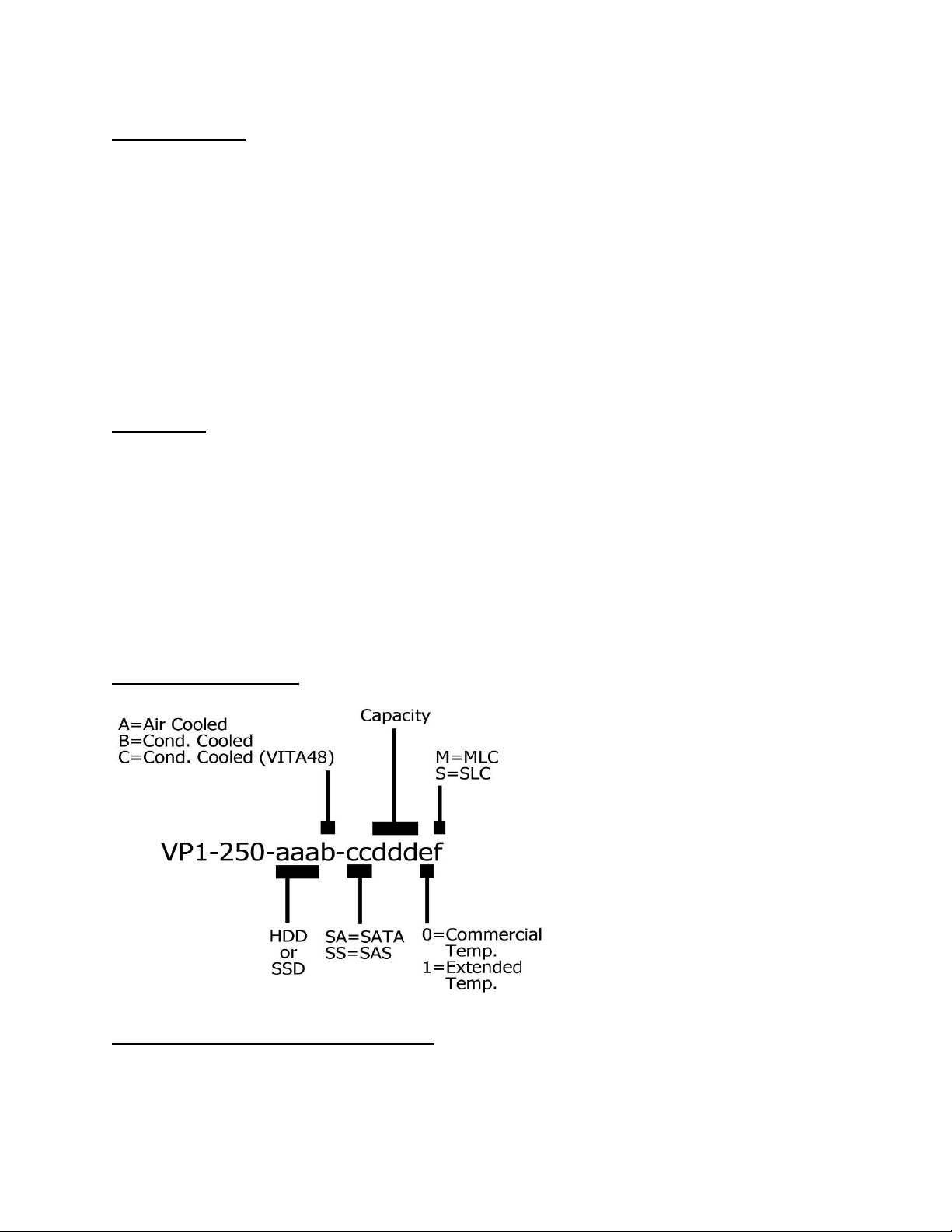
Part Number Key
Module and Backplane Profile
The VP1-250X is compatible with the following VITA profile: MOD3-STO-1U-16.5.1-2
VP1-250X User’s Manual - 3 - Revision E, September 2016
Page 4

Handling
To prevent damaging the module, be aware of the precautions you need to follow when
handling or installing the module. A discharge of static electricity from a finger or other
conductor may damage static-sensitive devices. This type of damage may reduce the life
expectancy of the device.
To prevent electrostatic damage:
- Avoid hand contact by transporting and storing products in static-safe containers.
- Keep electrostatic-sensitive parts in their containers until they arrive at static-protected
workstations.
- Place parts in a static-protected area before removing them from their containers.
- Avoid touching pins, leads, or circuitry.
- Always be properly grounded when touching a static-sensitive component or assembly.
Grounding methods to prevent electrostatic discharge
Several methods are used for grounding. Use one or more of the following methods when
handling or installing electrostatic-sensitive parts:
- Use a wrist strap connected by a ground cord to a grounded workstation or computer
chassis. Wrist straps are flexible straps with a minimum of 1 Megaohm (± 10 percent)
resistance in the ground cords. To provide proper ground, wear the strap snug against
the skin.
- Use heel straps, toe straps or boot straps at standing workstations. Wear the straps on
both feet when standing on conductive floors or dissipating floor mats.
- Use conductive field service tools.
- Use a portable field service kit with a folding static-dissipating work mat.
Installation
Ensure that all power is removed from the VPX backplane before inserting the module. Prior to
inserting the VP1-250X into the card cage, it is necessary to verify the slot the module will be
inserted into is compatible with the module. VPX modules are typically keyed to prevent the
insertion of a module into the wrong card cage slot. The VP1-250X utilizes two guide modules
with keying. In the standard configuration both guide modules are not keyed. Caution must be
used to ensure the module is not inserted into a slot that will cause damage to either the
module, the backplane, or any other device attached to the system. Guide module keying is
available with no key, 0°, 45°, 90°, 270°, and 315°.
Considerations for airflow provided to the module are important. Ensure that proper airflow is
provided to air-cooled modules. Conduction cooled modules should only be used in a properly
configured conduction cooled card cage. Operation of a conduction cooled VPX module in an air
cooled environment can result in overheating of the storage device.
VP1-250X User’s Manual - 4 - Revision E, September 2016
Page 5

Functional Block Diagram
VP1-250X User’s Manual - 5 - Revision E, September 2016
Page 6

Module Layout
Option Configuration
Purge/Zeroize, PCB location P3:
The Purge and Zeroize connections are provide to allow for triggering optional features of an
attached drive (dependent on drive capabilities). These connections, which are routed to the
VPX P1 connector, are not limited to these functions. They can be utilized to take advantage of
other drive dependent options such as write protect, or used for custom sensor or warning
circuits.
Safety Ground, Jumpers JP1 & JP2:
By installing jumpers at locations JP1 and JP2 the ground plane of the VPX module will be
connected to the VPX key guides. This allows for the option of connecting the VPX module
ground plane directly to the VPX chassis ground plane.
VP1-250X User’s Manual - 6 - Revision E, September 2016
Page 7

Connector Pin Definitions
P0
A B C D E F G
1
NC
NC
NC
NC
+12V
+12V
+12V
2
NC
NC
NC
NC
+12V
+12V
+12V
3
+5V
+5V
+5V
NC
+5V
+5V
+5V
4
NC
NC
GND
NC
GND
NC
NC 5 NC
NC
GND
NC
GND
NC
NC
6
NC
NC
GND
NC
GND
NC
NC 7 NC
NC
GND
NC
NC
GND
NC
8
GND
NC
NC
GND
NC
NC
GND
P1
A B C D E F G
1
NC
NC
GND
NC
NC
GND
NC
2
GND
NC
NC
GND
GND
NC
GND
3
NC
NC
GND
NC
NC
GND
NC
4
GND
NC
NC
GND
GND
NC
GND
5
NC
NC
GND
NC
NC
GND
NC
6
GND
NC
NC
GND
GND
NC
GND
7
NC
NC
GND
NC
NC
GND
NC
8
GND
NC
NC
GND
GND
NC
GND
9
RXP0_P
RXP0_N
GND
TXP0_P
TXP0_N
GND
DRIVE_LED
10
GND
NC
NC
GND
GND
NC
GND
11
NC
NC
GND
NC
NC
GND
PURGE
12
GND
NC
NC
GND
GND
NC
GND
13
RXS0_P
RXS0_N
GND
TXS0_P
TXS0_N
GND
ZEROIZE
14
GND
NC
NC
GND
GND
NC
GND
15
NC
NC
GND
NC
NC
GND
NC
16
GND
NC
NC
GND
GND
NC
GND
Pin
Description
1
Purge
2
Zeroize
3
Ground
VPX Connector P0:
VPX Connector P1:
Connector P3:
VP1-250X User’s Manual - 7 - Revision E, September 2016
Page 8

SAS/SATA Connector J1:
Pin
A
P1
NC
P2
NC
P3
NC
P4
GND
P5
GND
P6
GND
P7
+5V
P8
+5V
P9
+5V
P10
GND
P11
DRV_LED
P12
GND
P13
+12V
P14
+12V
P15
+12V
Pin
A
S1
GND
S2
RP+
S3
RP-
S4
GND
S5
TP-
S6
TP+
S7
GND
S8
GND
S9
RS+
S10
RS-
S11
GND
S12
TS-
S13
TS+
S14
GND
SAS/SATA Signal SAS/SATA Power
VP1-250X User’s Manual - 8 - Revision E, September 2016
Page 9

Specifications
Physical:
Form Factor:
3U VPX bus 6.30" (160mm), 3.94" (100.0mm)
Module Interface:
SATA or SAS
Flammability:
UL94V-0 – PCB made in the USA by a UL recognized manufacturer
Environmental:
Air Cooled Temperature:
0° to 55° C (Air flow requirement as measured to be greater than 200 LFM)
Conduction Cooled Temperature:
-40 to 85° C (Module MUST operate in a fully installed Conduction Cooled rack)
Conduction-cooled with REDI (Vita 48) covers Temperature:
-40° to 85° C (Module MUST operate in a fully installed Conduction Cooled, REDI cover
rack)
Vibration:
1g2/Hz, 15Hz-2KHz random; 10g Peak, 15Hz-2KHz sine
Shock:
20Gs each axis, 40g Peak, Sawtooth @ 11mSec
Storage Temperature:
-55° to 105° C
Relative Humidity:
5 to 95 percent, noncondensing
MTBF:
24,800,000 Hours @ 25° C (without drive).
* Must use a Solid State drive capable of temperature range and shock and vibration.
Compliance Specifications:
The VP1-250X SATA/SAS Drive Module is designed to meet CE Emissions specification EN
55022, CE Immunity specification EN 50082-2 and FCC 47 CFR, Part 15, Class A when tested in
a shielded enclosure. Meets VITA 46.0, 48.2 and 65: VPX System Specifications and Practices.
VP1-250X User’s Manual - 9 - Revision E, September 2016
Page 10

Warranty and Support
Warranty Statement
Phoenix International VPX products come with a “return-to-factory” warranty which covers
defects in materials and workmanship for a period of three years from the date of product
shipment to the customer, provided the product is unmodified and has been subject to normal
and proper use. Warranty on non-Phoenix International manufactured devices incorporated into
Phoenix VPX products is restricted to that provided by their manufacturer only.
If You Have a Problem
If you are having a problem with a Phoenix International product, you should call our main
number, (714) 283-4800, and ask for Customer Service. Please be prepared to supply as much
detail as you can concerning the nature of the problem and the conditions in which the problem
appeared.
Obtaining an RMA
In order to return the product for repair, the following steps are necessary:
1. Obtain a Return Materials Authorization number (RMA#) from Phoenix International
Customer Service.
2. Ship the product prepaid to the designated repair point.
3. Provide with the product a written description of the claimed defect.
Shipping the Product
Any product returned to Phoenix International should be in its original shipping carton if
possible. Otherwise the product should be carefully packaged in a conductive packing material
and placed in a cushioned corrugated carton suitable for shipping. Please mark the shipping
label with the RMA number and return it to:
Phoenix International
812 W. Southern Avenue
Orange, CA., 92865
Attn: Customer Service Department
RMA #: ___________
VP1-250X User’s Manual - 10 - Revision E, September 2016
 Loading...