

Page 1
Trans-O-Con@
Forged Branch
Connections
Specifications.. . . . . . . . . . . . . . . . . . . . . . . . . . . . . . 15
Trans-O-Con Features&Applications.. . . . . . . . . . 16
Trans-O-Con IndustryStandard Consolidation. . . . 17
Butt-Weld. . . . . . . . . . . . . . . . . . . . . . . . . . . . . . . . . 18
Threaded. . . . . . . . . . . . . . . . . . . . . . . . . . . . . . . . . . 18
Socket Reducing. . . . . . . . . . . . . . . . . . . . . . . . . . . . 19
Elbow&LateralConnections.................. 19
Page 2
PHOENIX TRANS-O-CON@ transition pipe connections are used successfullyin
numerous types of product distribution installations. The structurally reinforced design of our
~ products insures a connection that is equal in strength to the originalpipe. Material costs and
installationtime can be greatly reduced by usingTRANS-a-CON connections in new
construction as well as for plant conversions and in maintenance operations.
Facilitiesnow usingour branch connections include:power generating stations, commercial
& industrial buildings,chemical & petrochemical plants and refineries.
STRENGTH RATINGS
TRANS-a-CONconnectionshavestrengthratingsequalto seamlesssteel pipe.
Theseratingsarebasedonthe ASMECodefor PressurePiping,B31,the ASMEBoilerConstructionCode and
For example,an extra-strong TRANS-a-CON applied to extra-strong pipe pf the equivalent material provides 100%pipe
strength. A standard weightTRANS-a-CON provides 100%pipe strength when used on standard weight pipe.
TRANS-a-CON connections are manufactured according to the requirements of the ANSIstandard for Steel Butt Welding
Fittings(B16.9,latest modification);the ASMEstandard for Forged Fittings,SocketWelding andThreaded Fittings
(B16.11,latest modification),the ANSI standard for Pressure Piping(B31,latest modification),and MSSSP-97.
When TRANS-a-CON connections are installed as recommended, their bursting strength exceeds the computed bursting
strength of pipe or the designated weight or schedule number and material.
Certifications are provided upon request. 24-hour acces to specifications through electronic MTR'son our web site.
ANSI/ASME B36.1 O.
SPECIFICATIONS
Approval listings on file.
IDENTIFICATION AND MARKING
TRANS-a-CON connections are forged from carbon steel hot rolled bar to meet A-IOSmaterial specifications.
Everyconnection is individuallyinspected and stamped with header size, outlet size, material specification,
pressure rating, manufacturer's symbol and identification number.
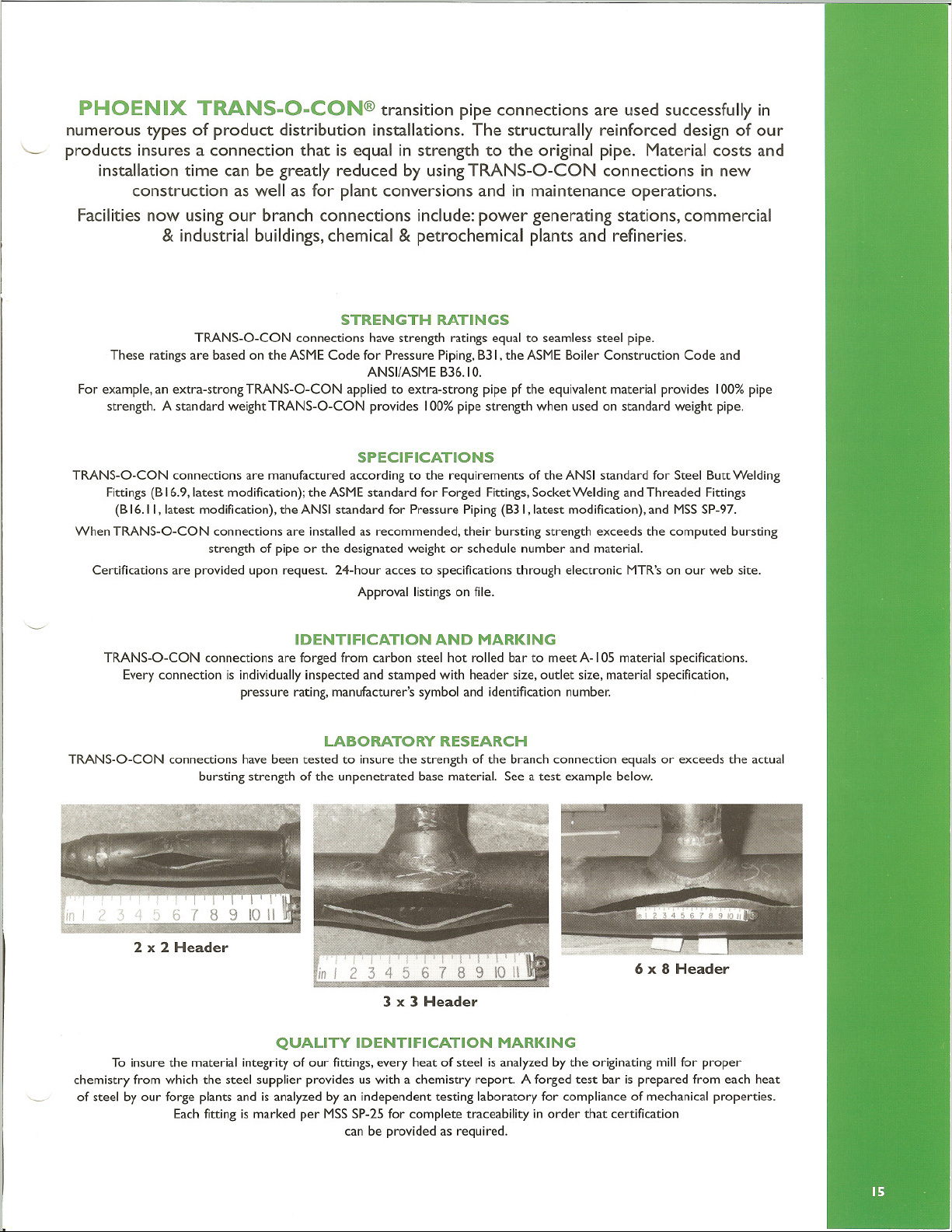
LABORATORY RESEARCH
TRANS-a-CONconnectionshavebeentested to insurethe strengthof the branchconnectionequalsor exceedsthe actual
burstingstrengthofthe unpenetratedbasematerial.See a test examplebelow.
2 x 2 Header
in j
3 x 3 Header
QUALITY IDENTIFICATION MARKING
To insure the material integrity of our fittings,every heat of steel is analyzed by the originating millfor proper
chemistry from which the steel supplier provides us with a chemistry report. A forged test bar is prepared from each heat
' ' of steelbyour forgeplantsandisanalyzedbyanindependenttestinglaboratoryforcomplianceof mechanicalproperties.
Eachfittingis marked per MSSSP-25 for complete traceability in order that certification
can be provided as required.
Page 3

...
. .
......................................................................................................................
+
ASME SA10S1 A3S0-LF21 MSS SP-97 1 POWER PIPINGASMEB31.1
LIQUIDTRANSPORTATION.ASME B31.41 ASTM A10S1 NACEMR017S
Phoenix Trans-a-Con@Conventional Butt-Weld Size Range
BUTT-WELD (STD & X STRONG) OUTLET SIZE-INCHES
REFININGASMEB31.31GASTRANSMISSIONASMEB31.8
ASME B16.91 ASME B16.111 ASME B1.20.1
5" 6" 8" 10" 12" 14"
14- 12"
36- 24" 24 - 20" 36" 36" 36" 36"
10
20 -16 18 -16 24" 24"
8
5 8 8
14 -12 14 - 12 20" 20" 20" 24" 24"
6 10 10 18" 18" 18" 20"
6 14"
TRANS-O-CON @ design provides
100% pipe strength and unrestricted fluid flow
TRANS-a-CON connections maintain the
strength of the run pipe and optimize
flow characteristics of the entire system.
The cutawaydrawing shows exactly
how this isaccomplished.
Additional TRANS-O-CON
Advantages:
.TAPERED TRANSITION
FROM BRANCH TO HEADER
AND HEAVY JUNCTURE
MINIMIZES STRESS
CONCENTRATIONS.
·Low Initial Cost
· Fast,EasyInstallation
· No Cutting, Shapingor Beveling
· Easyto Align
· Strength and quality Properties
Found Only in a Forged Product
.WIDE FOOTING IMPROVES
MECHANICAL STRENGTH TO
WITHSTAND VIBRATIONAL STRESSES.
16" 16"
14" 14" 16"
12" 12"
10"
J
~
16" 18"
30" 30"
24"
18" 18"
16"
.SHORT HEIGHT
PERMITS ACCESS TO
INSIDE SURFACE
TO INSPECT FOR
FULL-PENETRATION
WELD.
36"
20"
...................................................................................................................................
...................................................................................................................................
TRANS-O-CON @ Applications
Use TRANS-O-CON connectors instead of
·WeldingTees · Reinforced Branches · Non-Reinforced Branches
TRANS-a-CON transition pipe connections can be used in all of these applications to advantage.
Not only is the cost lower,but consider the TRANS-a-CON benefits shown below.
Why TRANS-O-CON connections
are better than welding tees:
·Quicker Fabrication time
·Pipe can be run before branch
connections are attached
·Gradual transition from header to branch
improves stress distribution
·Lower material costs
Why TRANS-O-CON connections
are better than Reinforced and
Non-Reinforced Miter Branches:
·Quicker installation
·Provides perfectly contoured internal joint
·Requires no shaping
·Requires less cutting and welding
·Eliminatesmetal-to-metallapped
surfaces and sharp corners
·Reduces overall cost of installation
TRANs-a-coN WELDING TEE
TRANs-a-coN MITERBRANCH
Page 4

...
Phoenix Trans.O.Con@ ASME SA105 I A 350-LF21 MSS SP-97 I POWER PIPING ASME831.1
Indust
Standard Consolidation LIQUIDTRANSPORTATIONASME 831.41 ASTM A1051 NACEMR0175
ry
REFINING ASME 831.31 GAS TRANSMISSION ASME 831.8
. .
+
Straight Bore Branch Connections ASME 816.91 ASME816.111 ASME 81.20.1
BUTT-WELD (STD)
I/)
1/4"
w
36-318" 36 -3/4" 36 -11/4" 36 -21/2" 36 -2" 36 -8" 36 -4" 36 -8" 36 -12" 36 -16" 36 -22" 42 -36"
N
1/4" 1/2
3/a" 1/2" 3/4"
_ 3/8" I -1/2" 2 -3/4" 31/2" -11/4"
OUTLET SIZE. INCHES
I" 11/4" 11/2" 2" 21/2" ]" 4" 6"
6 -21/2" 31/2" -2" 6-31/2" 10- 5" 14- 8" 20 - 12" 34 - 26"
- I" 2 - 11/2" 11/2" 3 -21/2" 4 -3" 6 -5" 10-8" 24 -20"
I/)
Z
:I
BUTT-WELD (EXTRA STRONG)
II:
1/4"
36-114" 36-1/2" 36 - I" 36 - 2" 36 - 2" 36- 6" 36- 4" 36- 8" 36 - 12" 36- 16" 36 - 22" 42 - 36"
w
a.
3/a" 1/2" 3/4" I"
3/8" 3/4"- 1/2" 11/2"_3/4"
3"- 11/4" 5 - 21/2" 31/2"- 2" 6 - 31/2" 10- 5" 14- 8"
I" 2 - 11/4" 11/2"
11/4"
OUTLET SIZE. INCHES
11/4"
11/2" 2" 21/2" ]" 4" 6"
-
a.
SOCKET-WELD (3000#)
I/)
1/4"
w
36 -318" 36 -3/4"
N
1/4" 1/2_3/8" 1/2"
-
I/)
Z
:I OUTLET SIZE
SOCKET-WELD (6000#)
II:
1/4" 3/a"
36 -1/4"
w
a.
-
a.
THREADED (3000#)
I/)
1/4" 3/8" 1/2" 3/4" 11/4" 11/2"
w
36 - 112" 36 -11/4" 36 -314"
N
3/8 -1/4"
I/)
Z
THREADED (6000#)
:I
II:
1/4" 3/8"
-112" 36 - 11/4"
36
w
3/8- 1/4"
a.
-
3/8"
36 -3/8" 36 -3/4" 36- 11/4" 36- 3" 36- 5"
1/2"
36 -3/4"
1/2" 3/4" I" 11/4"
1/2" I- 3/4"
3/4" I" 11/4" 11/2"
36 - 11/2" 36 -3" 36 -4" 36 -6" 36 -8"
11/4_314" 21/2-11/4" 31/2-2"
I"
21/2 - 11/4" 4- 11/2" 5- 3" 6 - 4" 18-6" 26- 12" 14- 10"
I" 11/4"
I"
-11/2" 36 -3" 36 -4" 36 -6" 36 -8" 36 -10" 36 -16" 36 -22"
36
I -3/8" 1/2"
1/2"
36 -314" 36- 11/2" 36 - 3" 36 - 10" 36- 6" 36 - 8"
I - 3/8" 1/2"
11/4
_ 314" 21/2-11/4"
I"
3/4" I"
21/2- I" 21/2-11/4"
-I" 31/2 -2" 21/2-2"
3/4"
11/4
a.
OUTLET SIZE -INCHES
5- 3" 6-4" 8-6" 14- 8" 20- 12"
11/2 - 11/4"
OUTLET SIZE. INCHES
31/2- 2" 5 - 3"
11/2- 11/4" 21/2- 2"
OUTLET SIZE
11/4" 11/2"
8 - 4"
11/2-11/4"
21/2 -2"
11/2"
11/2" 2"
36- 6" 36- 8" 36- 20" 36- 28" 36- 16"
21/2-2" 31/2 -21/2"
11/2" 2" 3 -21/2" 5 -4" 5"
11/2"
-INCHES
5- 3"
11/2" 2" 5 -4" 4" 6"
2"
3 - 21/2" 4 - 3" 6- 5" 10- 8" 24 - 20"
2"
2" 21/2" ]" 4"
31/2 -21/2"
2"
21/2" 4 -31/2"
3" 4" 14- 12"
21/2" 4 - 31/2"
3" 4" 14-12"
- 10" 36 - 16" 36 -22"
36
5 -4" 6 -5" 10-8"
31/2 -3" 4 -31/2" 6 -5"
21/2" 3" 4"
-INCHES
21/2"
5 -31/2" 10-6" 8 -6"
2" 21/2"
6- 4"
8 - 6" 14- 8" 20 - 12"
31/2- 21/2" 5 -4" 6- 5" 10- 8"
2"
2" 21/2" ]" 4"
31/2 -3" 4 -31/2" 6 -5"
21/2" 3" 4"
36- 28" 36 - 14"
6- 4" 26 - 12" 12-8" 18-12"
-21/2" 10-6" 6 -5" 10-8"
31/2
31/2 -3" 31/2" 5"
21/2" 3" 4"
]" 4"
31/2 -3"
]" 4"
6 -5" 18 -16"
10"
8"
6"
20- 12" 34- 26"
6- 5" 18- 16"
10"
8"
6"
FLATSI
available
I/a" thro.
6" pipe
outlet.
Tradition
line of ru
pipe size
available
on inquir
Size on
Size are
4"
conventi.
funneled
inlet desi
36- 20"
ES
gh
al
n
y.
nal
gn.
1/16"(~~hAP
MAXIM ~
1 <-. 36"RUNPIPE
SKIRT GAP
HOW CONDENSED SIZE WORKS:
Eachforged outlet size listed on the chart is designed to
fit a range of pipe run sizes.
For example: The 1/2"fitting marked 36-3/4" will fit each pipe
run size from 3/4" to 36". There will be a maximum 1/16"gap as
illustrated in diagrams. This gapis negligible when welding and
has no adverse effect on the integrity of the connection.
MINIMIZE WARHOUSE INVENTORY
CROTCH GAP
3/4" - 36" RUN PIPE
Page 5

...
. .
. . . . . . . . . . . . . . . . . . . . . . . . . . . . . . . . . . . . . . . . . . . . . . . . . . . . . . . . . . . . . . . . . . . . . . . . . . . . . . . . . . . . . . . . . . . . . . . . . . . . . . . . . . . . . . . . . . . . . .
+
STANDARD
1/4" .652 .364 .625 .302
3/a" .750 .493 .750 .423
1/2" .750 .622 .750 .546
3/4" .875 .824 .875
I" 1.063 1.049 1.063 .957 .50
11/4"
11/2" 1.313 1.610 1.313 1.500
2" 1.500 2.067 1.500 1.939 1.29 1.35
21/2" 1.625 2.469 1.625 2.323 1.75 1.82
3" I.750 3.068 1.750 2.900 2.63 2.75
4" 3.000 4.026 2.000 3.826 4.30 4.45
5" 2.125 5.047 2.125 4.813 9.59 6.39
6"
8"
10" 3.06 10.02 3.69 9.750 27.22 36.19
12" 3.38 12.00 4.06 11.750 34.00 67.00
14" 3.50 13.25 3.94 13.000 56.00 72.25
16" 3.69 15.25 4.18 15.000 76.00 102.10
18" 3.81 17.25 4.38 17.000 97.00 129.75
20" 4.00 19.25 4.69 19.000 120.00 166.00
24" 4.56 23.25 5.50 23.000 194.61 262.00
1.250 1.380 1.250 1.278
2.375 6.065 2.375 5.761 12.00 17.60
2.750 7.981 3.875 7.625 23.00 34.80
TRANS-O-CON@Butt-Weld Reducing Sizes
EXTRASTRONG I
.08 .10
.09
.35 .40
.742
.40
.70 .80
.75 .85
MSS SP-97
.15
.45
.60
STRAIGHT
THRU
BORE
.....................................................................................................................................
.....................................................................................................................................
TRANS-O-CON@Threaded Reducing Sizes
MSS SP-97
.
.
I/a" .750 .328 .875
1/4" .750 .437 .875 .10
3/a" .813 .562 1.000 .16
1/2" 1.000
3/4" 1.063 .906 1.438 1.438 .906
I"
11/4" 1.359 1.469 2.188 1.469 .90 1.50
11f2" 1.375 1.719 2.436 1.688 1.719 3.000 1.40 1.90
2" 1.531 2.188 2.938 2.063 2.188 3.625 1.80 5.00
21/2" 1.813 2.528 3.438 3.00
3" 2.000 3.203 4.125 4.35
4" 2.250 4.203 5.125 7.10
1.313 1.141 1.813 1.563 1.141 2.250 .70 1.20
NOTE: NPTThreads
to 81.20.1.
IItH-.
6000# ul
.703 1.250 1.250 .703 1.563
1.813
,"J;j;{.>.«.~::H
IiI.I'J~I.J,.'"
11111"1__.1"111-'
.10
.25 .40
.38 .70
~ NEW FORGING
TECHNOLOGY ~
i:SOO::'4.i:j674.p~~~~~.I~~.~i~..:... i:ssii.7.44:ij26L~~i;i.~~~...
Page 6

. .
...
TRANS.O.CON@Socket Reducing Sizes
MSS SP-97
.
I/a" .750 .364 .10
1/4" .750 .364 .10
3/a" .813 0493 .16
1/2" 1.000
3/4" 1.063
I" 1.313 1.049 1.563 .8153 .70 1.10
J1/4" 1.359 1.380 1.625 1.160 .90 1.50
11/2" 1.375 1.610 1.668 1.338 1040 1.80
2"
21/2" 1.563 20469 2.75
3" 1.750 3.068 3.80
4" 1.875 4.026 7.25
1/16" NOTE: Socket minimum depth per ANSI B 16.11.
1111I-.
.622 1.250 0464 .25
.824 10438 .612
1.531 2.067 2.063 1.687 1.80 4.70
+
6000#
'11I'.;__.11111I-.
AS
.38 .70
.....................................................................................................................................
.....................................................................................................................................
TRANS.O.CON@Elbow. Lateral Connections
3000# for 90° long radius pipe elbows ButtWeld / Socket / Threaded
SIZES SIZE WEIGHT
(INCHES) (INCHES) C
ELBOW
36 -3/4" 1/2"* 1.500
36 - I" 3/4"* 1.813
36- 2" I" * 2.250 2.188
36- 2" 11/2" 3.125
36- 3" 2" 4.188
45° LATERAL
THREADED
LATERAL
CONNECTION
I OUTLET .-wl[)]IIMIE::INS:1I[O.]NS:1...n..
1/2"*
12-3 12 - 6 12 -6 12 -6 12 -10 12 - 10
21/2
-11/4 5 -3 5 -3 5 -3
3/4"* 11/4" 11/2"1"* 2"
21/2- 2 21/2- 2 21/2- 2 5-4 5-4
*Available in 6000#
SOCKET
LATERAL
CONNECTION
E
1.594 .50
1.875 .70
2.625 2.65
3.185 5.25
APPROX.
POUNDS
1.15
8-6 8-6
THREADED
FULL
PENETRATION
WELD
SOCKET
FULL
PENETRATION
WELD
NOTE: Butt-Welding end dimensions to ANSI B16.9 and ANSI B 16.25.
.Ui:800-44.:j.74'p;.;;;YI~';';j~.U:..i:...:7.;':,'ii6.':;';;~i';;';;.. u. U 00 0000 ... . U U U. 00 U. U U. U U. U U U 00 00.00 0000.001
 Loading...