

Phoenix SPC10e Instruction Manual

Instruction & Maintenance Manual Sheet 1.21
INSTRUCTION MANUAL
For the
Phœnix
‘SPC10e’
Self Propelled
Metering
Chipping Spreader
Section 1.2
Drive Controls,
Engine & Transmission System
Phoenix ‘SPC10e’ Self Propelled Metering Chipping Spreader 03/12

Instruction & Maintenance Manual Sheet 1.22
Blank
Phoenix ‘SPC10e’ Self Propelled Metering Chipping Spreader 03/12

Instruction & Maintenance Manual Sheet 1.23
1.2.1 Operator’s Position -
Layout of Controls & Instruments
Always enter the Operator’s (Driver’s) position by climbing the
access steps to the front on either side. Normally enter the
machine from the LH side as the armrest and joystick obstructs
access for the RH side.
A second seat allows for an additional person to be carried.
However, there are no operating functions for this person. Any
person in this seat must not distract the operator.
HAZARD WARNING
DO NOT CARRY other persons, other than where the
seat is provided.
DO NOT ALLOW any person to climb onto or off the
machine whilst it is moving, including use of the
normal access steps.
AT NO TIME leave the operator’s position with the
machine still moving. ALWAYS place drive control to
neutral and apply the parking brakes.
ALWAYS ENTER & EXIT the operator’s position via the
access steps unless in an emergency you are unable
to do so.
Once seated in the main operator’s position, the controls
necessary to operate the machine are grouped around the seat.
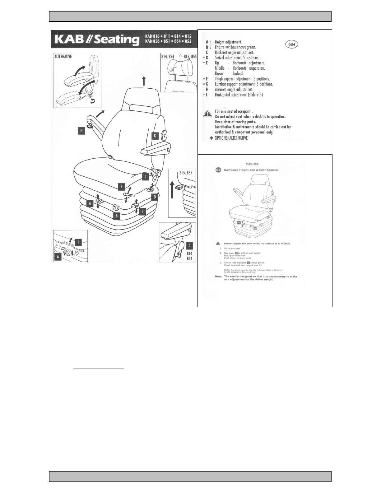
Seat and Front Steering Column
The operators seat is fitted with a self contained air suspension
to protect the operator from the immediate vibration of the
machine’s motion. The seat is adjustable for height,
forward/rearward position, back rake and posture.
The front steering column and console is adjustable for angle so
that it can be moved towards the seat or towards the
windscreen. A locking screw on the LH side under the main
console slackens the column to allow adjustment.
Phoenix ‘SPC10e’ Self Propelled Metering Chipping Spreader 03/12
Instruction & Maintenance Manual Sheet 1.24
A new operator should adjust the seat and column to their
individual comfort and to ensure that all controls are easily at
hand without, particularly ensuring the foot brake can be
reached in an emergency.
IMPORTANT
Ensure the column is locked and secure BEFORE
moving off.
DO NOT attempt to adjust the column with the
machine in motion.
The cab floor, either side of the centre is glazed with Perspex to
allow the centre spread feedroller to be visible. The Perspex
panels are hinged and a square key is provided to allow them to
be opened for cleaning.
Phoenix ‘SPC10e’ Self Propelled Metering Chipping Spreader 03/12

Instruction & Maintenance Manual Sheet 1.25
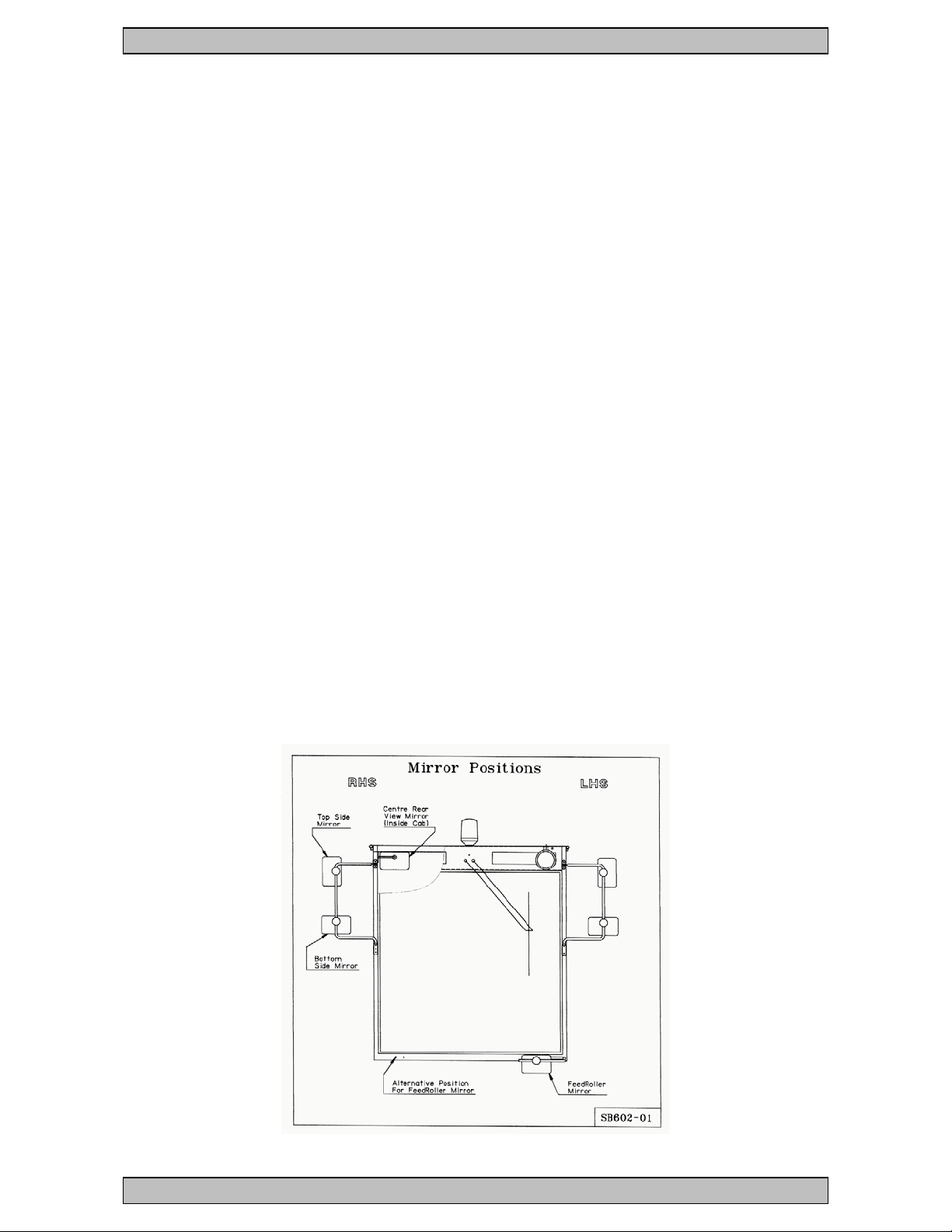
Visibility & Mirrors
Five mirrors are provided on the cab frame to give full side and
rear visibility. These should be set so that the full envelope of
the machine; over the rear receiving hopper; across to the
extension spreading hoppers & down the sides of the machine;
can be viewed, particularly any person moving around the
machine.
When correctly adjusted, using all five mirrors together, it is
possible to see a person continuously as they move around the
machine remaining close to the side and back; i.e. within
300mm
[1 ft]. However the area immediately behind the rear receiving
hopper can be partly obscured and may require the rear hopper
sides to be in the lowered position.
HAZARD WARNING
With the rear folding sides in their raised position,
the area immediately behind the machine may not be
fully visible. When reversing, either lower the folding
sides to give make this area fully visible or move the
machine one metre forward to check the reversing
area is clear before starting the reverse manoeuvre.
Always ensure when carrying out reversing
manoeuvres that the area to the rear and immediately
to the sides into which the machine is moving is clear
of any persons or obstruction. STOP IMMEDIATELY if
your visibility is restricted into this area.
Convex mirrors distort perspective - people and
objects may be closer than they appear in the
mirrors.
IMPORTANT
The mirrors must all be present and adjusted, as
stated below before using the machine.
There are FIVE rear view mirrors fitted to the machine that must
be adjusted as follows –
Rear view inside cab gives a view over the operator’s
shoulder. Adjust so that both sides of the rear receiving
hopper are visible when lowered. The view should also
allow the inside of the raised body of the supply truck to be
seen when being towed.
Phoenix ‘SPC10e’ Self Propelled Metering Chipping Spreader 03/12
Instruction & Maintenance Manual Sheet 1.26
Top side mirrors (LH & RH), located at top of mirror arms,
give a rear view along the side of the machine so that the
area immediately behind the front hopper and back is
visible. Adjust so the top of the rear tyre is visible in the
centre inside of the mirror. This gives a view into the top of
the front spreading hopper of the machine on the inside of
the mirror and a view into and over the rear receiving
hopper folding side on the top inside of the mirror.
Bottom side mirrors (LH & RH), located at bottom of the
mirror arms, give a side view immediately outward of the
front spread hopper and back along the side, including the
extension spreading hopper when out. Adjust so the area
immediately to the side of the machine (side of front
spreading hopper) is visible. Approximately 3 metres
further to the side of the machine and rearward to the
centre of the machine should be visible.
A further sixth mirror is located at the level of the
operator’s platform, front LHS or RHS, attached to its own
arm. It is placed to view the centre spreading feedroller. It
can be adjusted to see about 2/3rds of the feedroller and
the aggregate falling to the road surface. It can be placed
on either side of the cab as desired. This mirror is not
required for safe manoeuvring of the machine. It is however
of the same type as the side mirrors and may be used to
replace them should the need arise.
Phoenix ‘SPC10e’ Self Propelled Metering Chipping Spreader 03/12

Instruction & Maintenance Manual Sheet 1.27
Reverse Warning Bleeper
The reverse warning bleeper will sound at a high pitch to attract
the attention of anybody close to the machine. When reverse is
selected it will sound to alert anybody to the side or behind the
machine that it is immediately about to manoeuvre backwards.
The volume emitted by the bleeper will increase as background
noise increases.
IMPORTANT
DO NOT obstruct the reverse warning bleeper, as this
may effect the sound level emitted.
Daily, before starting to use the machine the reverse
warning bleeper MUST be tested to ensure its
operation.
There is no manual OFF switch provided and the
reverse warning bleeper must always sound when
reversing.
Hazard Warning
DO NOT use or continue to use the machine unless the
reverse warning bleeper is working.
DO NOT rely on the reverse bleeper sounding to ensure
that people move clear of the machine. Always check and
continue to look all around the machine with the visibility
aids supplied.
DO NOT allow the machine to roll back without selecting
reverse gear, as the bleeper will not sound.
Phoenix ‘SPC10e’ Self Propelled Metering Chipping Spreader 03/12
Instruction & Maintenance Manual Sheet 1.28
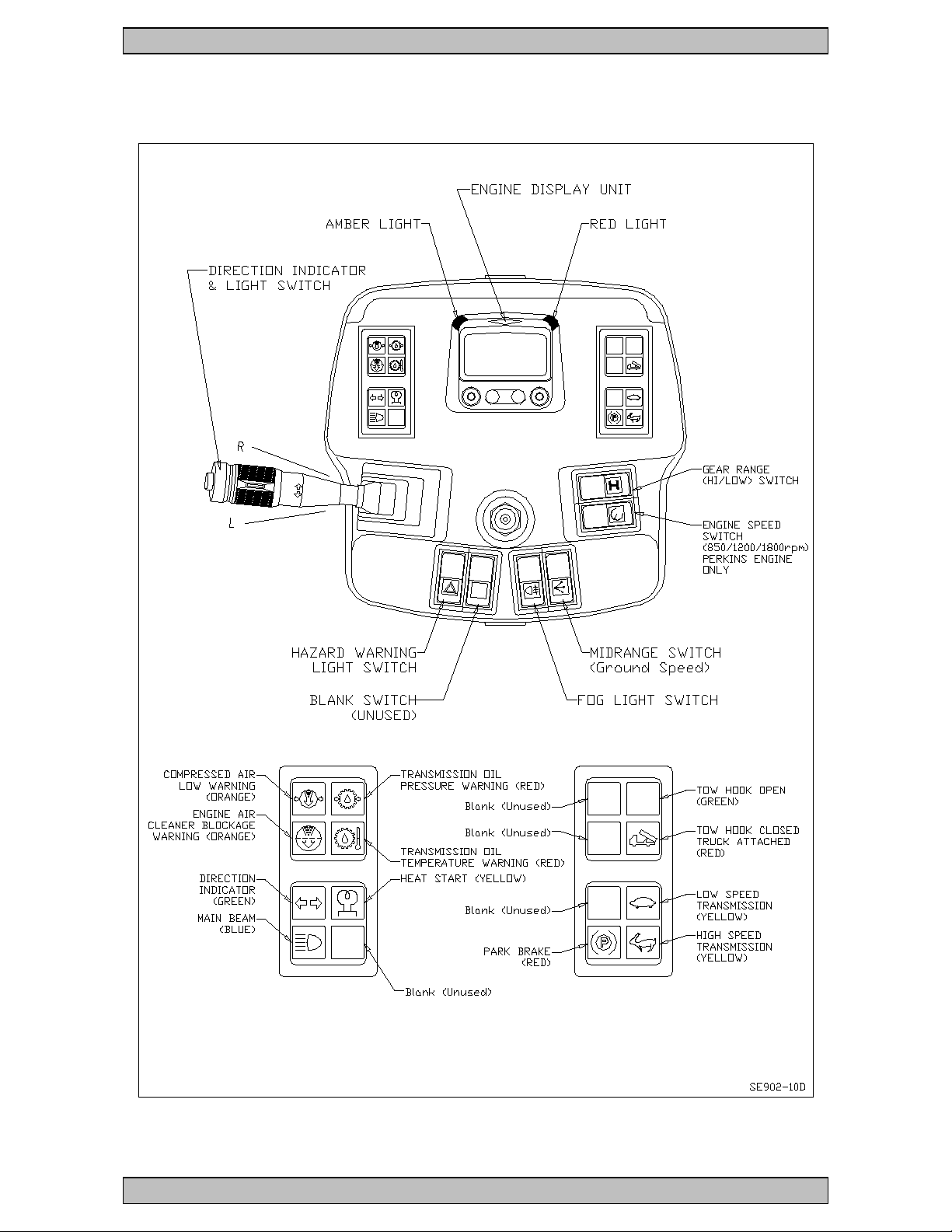
Controls Layout – Front Console
H
H
Phoenix ‘SPC10e’ Self Propelled Metering Chipping Spreader 03/12

Instruction & Maintenance Manual Sheet 1.29
Control & Gauge Types and Locations
The following engine and transmission controls are provided for
the operator of the ‘SPC10e’. They are located in either the –
Front steering column and console, immediately to
front
Stack on steering wheel column
Side arm console (part of seat arm rest)
Foot controls in floor under the front console
Right (RH) console adjacent to right armrest
Overhead console above the windscreen
Location
Ignition switch (key switch) front console
Engine throttle control switch - PERKINS front console
Engine throttle control switch - JCB RH console
Parking Brake RH console
Brake foot pedal (service brake) floor
Steering control (wheel) front console
Joystick with additional switches side arm console
Speed control switch (Low/High) front console
Ground Speed Adjuster RH console
Ground Speed ON/OFF switch RH console
Indicator/headlamp dip/horn stalk stalk
Headlamp/sidelamp switch front console
Headlight dip/mainbeam control stalk
Horn warning switch stalk
Hazard beacon switch. front console
Fog light (rear) switch front console
Windscreen wiper switch overhead console
Windscreen washer switch. overhead console
Working lights – Cab roof overhead console
MidRange Speed switch front console
See Fig. SE902-10,
SE902-05B (PERKINS) &
SE902-26D (JCB)
Phoenix ‘SPC10e’ Self Propelled Metering Chipping Spreader 03/12
 Loading...