

Page 1
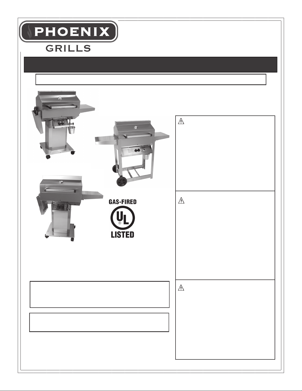
Owner’s Manual
Assembly and Maintenance Instructions
THIS GAS APPLIANCE IS DESIGNED FOR OUTDOOR USE ONLY.
FOR YOUR SAFETY
If you smell gas:
1. Shut off gas to appliance.
2. Extinguish any open flame.
3. Open Lid.
4. If odor continues, immediately
call your gas supplier or your
fire department.
FOR YOUR SAFETY
MH49347
Model: SDRIVDD - SDRIV4LDD - SDWELD
THESE INSTRUCTIONS SHOULD BE LEFT WITH
THE CUSTOMER. KEEP THESES INSTRUCTIONS
FOR FUTURE REFERENCE.
YOU MUST READ THIS OWNERS MANUAL BEFORE
OPERATING YOUR GAS GRILL.
1. Do not store or use gasoline or
other flammable vapors and liquids in the vicinity of this or any
other appliance.
2. An LP cylinder not connected
for use shall not be stored in
the vicinity of this or any other
appliance.
FOR YOUR SAFETY
Follow all leak-test procedures
carefully in this manual before using. Do this even if the grill was
dealer assembled. Do not try to
light this appliance without read-
ing the “Lighting” instructions in
this manual.
3/17
Page 2
Note To Customer:
We recommend that you “break in” your grill by cooking the first two or three times at medium or low
temperature settings. This allows the cast aluminum drip pan to “season/break in’.
Caution: We recommend after each use, you turn the control knobs to HIGH (with the lid closed)
and run the grill for approximately 10 minutes. This will allow the accumulated fats and greases to
cook off, and avoid a possible flare up on the next use. HINT: The fats and greases are cooked off
when no more smoke is flowing from the grill vents.
READ this book first!
SAVE this manual for future reference!
Safety
Your new gas grill is a safe, convenient appliance when assembled and used properly. However, as with all
gas-fired products, certain safeguards must be observed. Failure to follow these safeguards may result in
hazardous fire or an explosion causing serious bodily injury or property damage. If you have any questions concerning the assembly or operation of this appliance after reading these instructions thoroughly, consult your dealer, gas appliance serviceman, or your propane gas company.
CALIFORNIA PROPOSITION 65 WARNING: Chemicals known to the Sate of California to cause
cancer, and birth defects or other reproductive harm are created by the combustion of propane, charcoal,
wood products, or natural gas used with this grill, and in the preparation of grilled foods.
The SAFETY symbol identifies the most important safety messages in this manual. When you see
the SAFETY symbol, Be Alert to the possibility of personal injury and carefully read the messages that follow.
Installer: This instructions MUST be left with the consumer.
Consumer: Retain these instructions for future use.
SAFETY
For Your Safety
Never check for gas leaks with a lighted match or open flame.
-This grill is for outdoor use only.
-Never leave a lit grill unattended.
-Do not let children operate or play near your grill.
-This grill is for use with propane gas only.
-Always leave filled cylinders outdoors.
Plan The Location Carefully
This grill is for outdoor use only. The grill is not to be used in a building, garage or any other enclosed area.
Installation of this appliance must be in accordance with all applicable local codes and gas utility requirements. In the absence of local codes, installation must be in accordance with current National Fuel Gas Code,
Z223,I/NFPA54 (Latest Edition) or CAN/CGA-B149.1, Natural Gas Installation Code or Can/CGA-B149.2 Propane Installation Code.
This appliance is for outdoor installation only in a well ventilated space. This grill is not intended to
be installed in or on any recreational vehicle and/or boats.
2
Page 3

SAFETY
IMPORTANT!
Check for compliance to these safety rules before each use!
-Maintain a minimum clearance of 24 inches
(61 cm) from sides and back of the grill to
any combustible construction.
-Do not use this appliance under overhead
combustible surfaces.
-Always keep the area around the grill clear
from any combustible materials, gasoline,
and other flammable gas and liquids.
-Do not block air to the appliance.
-Do not block ventilation openings.
LP Gas Cylinder
The LP Gas Cylinder which you purchase separately for use with this grill must meet the following requirements and be equipped with a
listed Overfilling Protection Device.
All LP gas cylinders used with this appliance
must be approximately 12" (30.5 cm) in diameter and approximately 18" (45.7 cm) in height.
The maximum fuel capacity shall be 20 lbs.
(9.1 kg) of Propane (43.7 lbs. normal water capacity). The propane tank must be provided
with a shut-off valve terminating in a propane
gas tank valve outlet and be provided with an
overfilling protection device.
Please Note: Your Propane Tank accepts a
Type I, also known a “Quick Connect
Valve”
SAFETY
OPD—Overfilling Protection Device
As stated, the cylinder you purchase must be
equipped with an overfilling protection device.
This type of cylinder can be identified by its triangular shaped tank valve and handle (see
page 9 for diagram of tank valve and handle).
Be Certain if you exchange your cylinder, that
the cylinder you receive in exchange has this
new OPD safety device.
The cylinder must be arranged for vapor withdrawal and remain in the upright position. The
cylinders must include a collar to protect the
cylinder valve.
All LP gas cylinders used with this appliance
must be marked in accordance with the specifications for LP gas cylinders of the US Depart-
ment of Transportation (DOT), or the National
Standard of Canada CAN/CSA-B339 Cylinder, Spheres and Tubes For Transportation of
Dangerous Goods, and Commission as Applicable.
Use of LP Cylinder
Refer to the assembly instructions section
and the label on the LP cylinder for guidance on proper installation and disconnection of the LP cylinder.
SAFETY
Use of Cylinder Dust Cap
The cylinder dust cap provided with your tank
must be used whenever the cylinder tank is
not connected to the grill gas system. Install
the dust cap onto the tank valve. Always use
the tank dust cap and be sure the tank valve
is closed when storing or transporting the
tank.
NOTE:
-The tank valve must be closed even when
using the dust cap.
-Always transport, store and use the tank in
an upright position.
-DO NOT take or store the tank in a building,
garage or enclosed area.
-Always keep the tank valve closed when the
grill is not in use.
-When removing the dust cap, do so slowly
and only after checking to ensure that the
tank valve is still closed.
-Read and follow all safety rules in your in struction books and on cylinder tank.
SAFETY
Filling the LP Cylinder
Have the tank filled by a reputable propane
gas dealer. The air must be purged from the
tank by your propane gas dealer before the
first filling. Have your propane gas dealer
check the relief valve after filling to ensure
that it remains free to function, and check for
leaks.
SAFETY Storage
DO NOT store the LP cylinder in direct sunlight. When the grill is to be stored indoors,
the propane tank MUST be disconnected. The
propane tank must be stored outdoors in a
3
Page 4

well ventilated space, NOT in a building, garage, or any other enclosed area. It must be out
of reach of children. A dust cap MUST be used
whenever the tank is disconnected from the
grill. When grill is not in use, close propane tank
cylinder valve.
When the propane tank is connected, the grill
must be stored outdoors in a well ventilated
space, not in a building, garage or any other
enclosed area. Always close the propane tank
before disconnecting it from the grill or when
the grill is not in use.
If the grill is going to be stored for winter or for
an extended period of time, we suggest you follow these steps:
-The burner should be cleaned and coated
lightly with cooking oil to prevent from rusting.
-The venturi openings should be covered with
aluminum foil to prevent small insects from
entering the opening during storage and must
be removed before using.
-The grill should be covered if it is left outdoors.
Grill covers are available as an accessory.
-Follow the cleaning procedures.
Hose and Regulator
The pressure regulator and hose assembly supplied with the appliance must be used. This
pressure regulator is preset for an outlet pressure of 11 inches (27.9 cm) water column.
Therefore, this pressure regulator MUST be
used with your Phoenix Grill. Before each use
of the grill inspect the hose for wear, cracking
and examine for any cuts. If any these conditions exist, do not use, purchase a new hose
and regulator. If a replacement is needed, refer
to the parts list for the part number and contact
the dealer where your grill was purchased. Refer to “Connecting the Cylinder to the Grill”
for details of hooking up your regulator to the
LP gas cylinder. Make sure a leak test is performed every time you have your LP gas cylinder refilled, and visibly inspect for excessive
wear and damage on a regular basis. Always
follow the directions for the “Leak Test”.
Natural Gas
Your grill may be converted to natural gas by
replacing the LP Valve with the appropriate Natural Gas Valve. (Part #HHVLV32-SD). A conversion should only be made by an authorized
Phoenix Grill dealer or local gas utility in accordance with all applicable codes. CAUTION:
Any additions, changes, or conversions required in order for the appliance to satisfactorily
meet the application needs must be made by a
Phoenix dealer or local gas utility using factory
specified and approved parts. Always remember to shut gas off at gas connection when grill
is not in use.
SAFETY
Leak Test
Check for leaks before lighting the grill for the
first time, after storing the grill between seasons
and after refilling the propane cylinder.
Take your grill outdoors into a well ventilated area. Do not use or permit sources of ignition in the area during this test, this includes smoking. Use only a soap and water
solution to test for leaks.
Leak Test Check List
-Tank valve (all over) including area that
screws into the tank and the welds.
-Regulator fitting
-Hose connections
-Valves
Mandatory Leak Test
1. Have propane tank filled with propane gas
only by a reputable propane gas dealer.
2. Attach regulator fitting to tank valve.
3. Tighten regulator fitting securely.
4. Turn the control knobs to the right, clockwise.
This is the “OFF” position.
5. Make a solution of half liquid detergent and
half water.
6. Turn gas supply “ON” at the tank valve
(counter clockwise).
7. Brush soapy mixture on all connections listed
in the Leak Test Check List.
8. Observe each place for bubbles caused by
leaks.
9. Tighten any leaking connections, if possible.
If leak cannot be stopped, DO NOT USE
THE GRILL. Order new parts from an
authorized Phoenix dealer. Do not use the
grill until after the new parts are installed.
After installing new parts, perform complete
leak test.
10. Turn gas supply “OFF” at the tank valve.
4
Page 5

Phoenix Grill WARRANTY
LIMITED LIFETIME WARRANTY ON THE FOLLOWING:
(Against Rust Through)
Welded Stainless Steel Grill Top & Bottom
10-YEAR WARRANTY ON THE FOLLOWING:
(Against Rust Through)
• Riveted Stainless Steel Grill Top & Bottom • Stainless Steel Control Panel •
Stainless Steel Column & Base • Stainless Steel Burner • Stainless Steel Cooking
Grid • Stainless Steel Side Shelves • Cast Aluminum Drip Pan
1-YEAR WARRANTY ON THE FOLLOWING:
(Against Rust Through)
All other Components including; • Igniter System • Gas Valves • Knobs • Drain Valve
• Temperature Gauge • Grease Bucket • Hose & Regulator
• Wheels • Hood Handle
WHAT IS NOT COVERED:
Surface Corrosion and Discoloration • Transportation and shipping cost • Labor for replacement or repairs • Damage from accident, misuse, alteration, abuse, improper installation or
storage • Removal and reinstallation costs • Finishes on surface that are damaged by improper installation, improper storage, accident, misuse, abuse or alteration • Inoperable due
to improper installation or storage • The costs of a service call to diagnose a problem • All
warranties are non-transferable and apply only to the original purchaser • Warranties are
null and void if grills are put into commercial or community use. This warranty does not imply or assume any responsibility for consequential damages that might result from use, misuse, or improper installation of this cooking appliance. This warranty does not cover claims,
which do not involve defective workmanship or materials, bill of sale, cancelled check, or
payment record should be kept to verify purchase date and establish warranty period.
MODEL IDENTFICATION
Your Phoenix Grill is identified by a model number and a serial number located on the left side of the control panel. Always
use both the model and serial numbers when contacting ProFire Grills about your grill. For future reference, take the time
now to record the model and serial numbers below:
MODEL NUMBER: ______________SERIAL NUMBER: ________________DATE PURCHASED:__________________
How to contact us: phone: 1-888-781-4657, fax: 1-800-781-3965, E-mail: info@profiregrills.com or write: Customer
Service, ProFire Grills 5565 North 124th Street, Butler, WI 53007.
5
Page 6
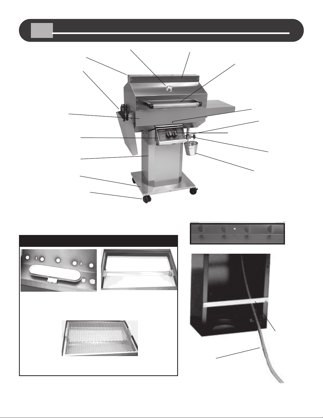
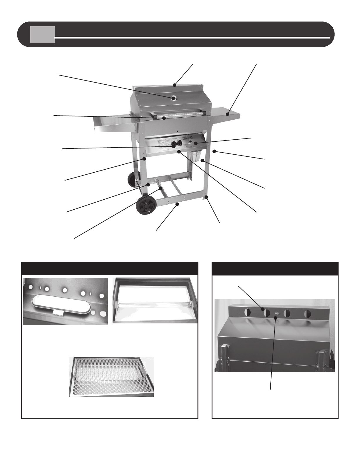
GETTING TO KNOW YOUR PHOENIX GAS GRILL
Vents on
Back of Lid
Side Shelf
Grill
Fire Pit
Control Panel
Column
Base
Locking Casters
Heat Indicator
Grill Lid
Sta-Kool
Swivel Handle
Match
Hole
Electronic
Igniter
Left and Right Burner
Controls
Drip Pan Drain
Valve
Grease/Water
Collector Bucket
Dual Burner and
Gas Collector Box
INSIDE VIEW
Stainless Steel
Cooking Grid
Vents On
Rear Of Lid
Back View of
Column
Cast Aluminum
Drip Pan
Tank
Locking Bar
On Propane
Model
12 Ft. Hose with
Quick Disconnect
Included with
Natural Gas Model
6
Page 7
Phoenix Grill Assembly Instructions
Carton contains the following components for assembly:
Please check to be sure that all parts are included before proceeding.
Contact your dealer or the factory if any parts are missing.
Hardware/Fasteners
Grill and Cart Components
Grill Lid 1
Grill Bottom with Pre-Assembled Burner, Gas
Collector Box and Igniter Wire
Hinge Pins and Clips 2 Each
Column 3 (Front, 2 Sides)
Tank Locking Bar (See Pre-Pack Below)
(Propane Model)
12 Ft. Hose with Quick Disconnect
(Natural Gas Model)
Base 1
Locking Casters 4
Control Panel with Pre-Assembled Valve,
Hose, Regulator and Igniter
Burner Control Knobs 2
Electronic Igniter 1
Temperature Gauge 1
Shelf Brackets, Shelves
(See Pre-Pack Below)
Stainless Steel Handle, Handle End Caps
(See Pre-Pack Below)
1
1 Pre-Pack
1
1
1 Pre-Pack
1 Pre-Pack
HARDWARE QUAN. USE
1/4-20 x 1/2” Hex Head Bolt 12 Column to Base
KEP Nut 12 Column to Base
1/4-20 x 1/2” Hex Head Bolt 8 Heat Shield to Column
KEP Nut 8 Heat Shield to Column
1/4-20 x 1/2” Hex Heat Bolt 6 Grill Bottom to Column
KEP Nut 6 Grill Bottom to Column
KEP Nut 2 2 Threaded Studs on
1/4– 20 x 1/2” Hex Head Bolt 2 Control Panel to Column
KEP Nut 2 Control Panel To Column
Hinge Pin 2 Lid to Grill Bottom
Hinge Clip 2 Lid to Grill Bottom
1/4-20 x 1/2” Hex Head Bolt 16 Casters to Base
Fastener Totals
Hex Bolts 1/4-20x1/2 ........................................................................52
Kep Nuts............................................................................................42
Hex Bolts 1/4-20x3/4...........................................................................4
Pan Head 10-24 x 1/2”……………………………………………………8
Nylon Lock #10…………………………………………………………….8
Lock Washer #10…………………………………………………………..8
Cast Aluminum Drip Pan 1
Stainless Steel Cooking Grid 1
Drip Pan Drain Valve 1
Collector Bucket 1
Heat Indicator 1
Tank Locking Bar- Nylon Spacer, 2 -3/4” Hex Bolt, Flat Washers (4) and Kep
Nuts (2)
Handle– Handle End Caps (2), Graphite Gasket (2), Hex Bolts (2), Flat Wash-
ers (4) and Kep Nuts (2)
Shelf Assembly– Shelf Brackets (4), Shelves (2), Hex Head Bolts (8), #10
Lock Washer (8), 10/24” x 1/2” Pan Head (8), Nylon Lock Nuts
(8),and Kep Nuts (8)
Pre-Packaged Part and Fasteners
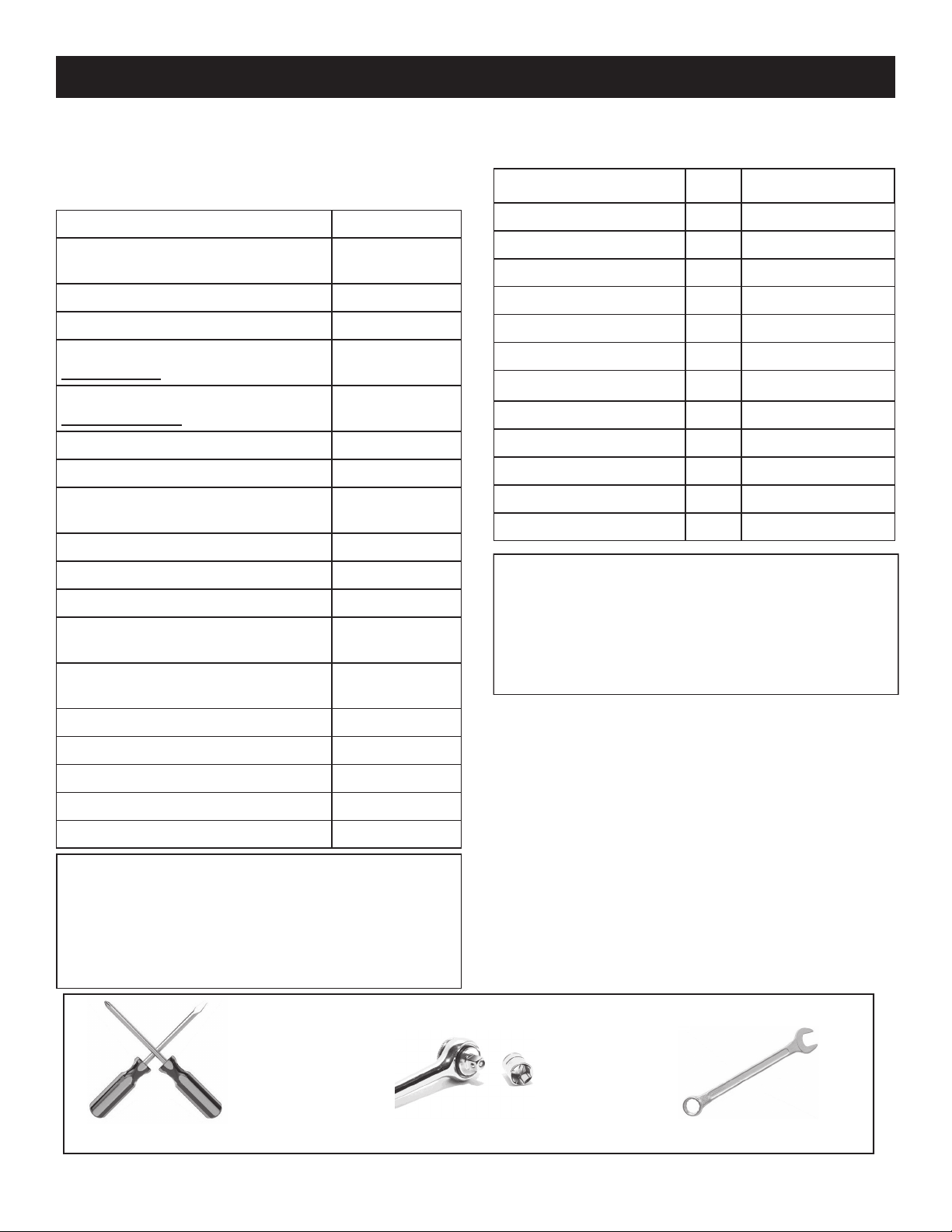
TOOLS NEEDED FOR ASSEMBLY
Phillips and Straight Screw Driver
7/16 Socket or Nut Driver
7/16 Wrench
7
Page 8
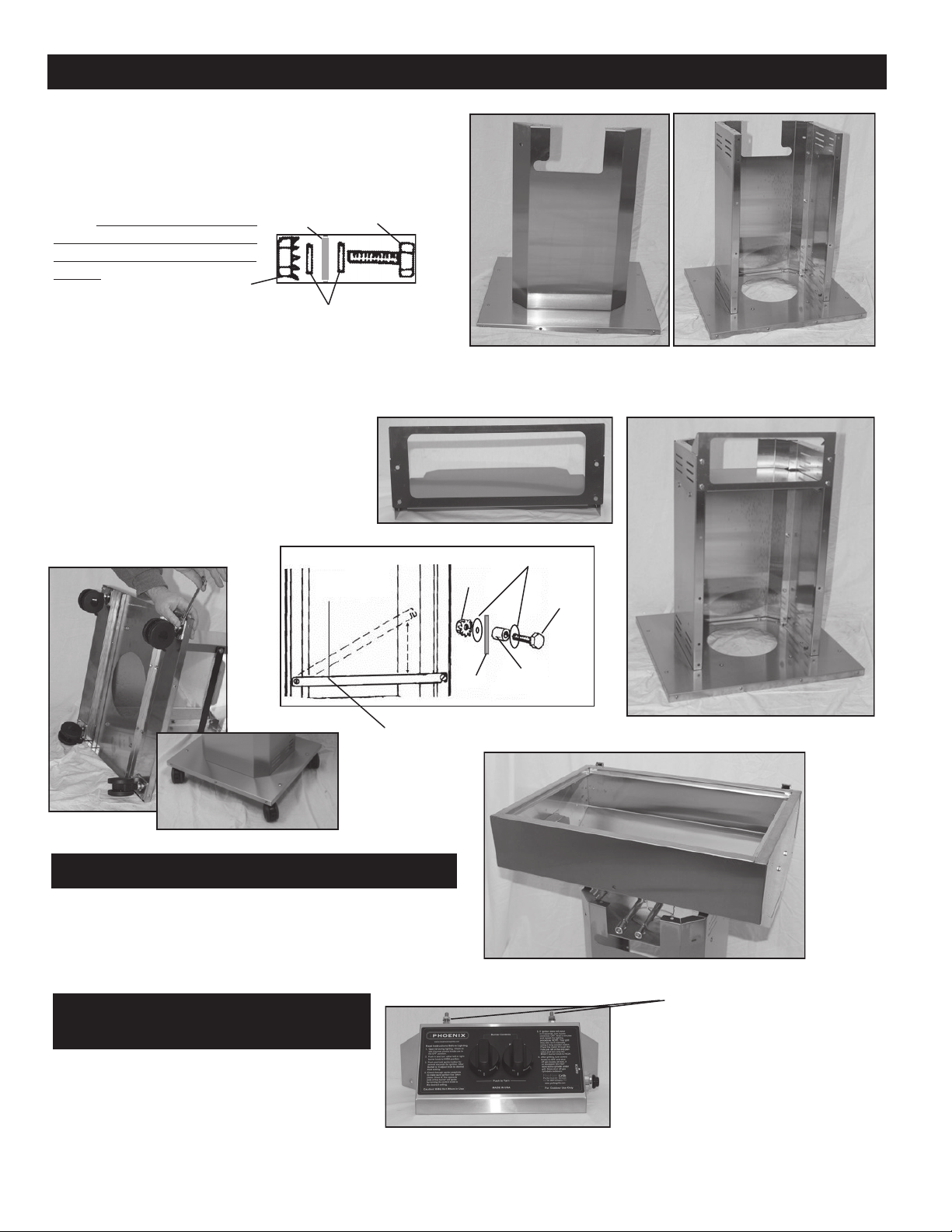
Step 1: Mounting Column to Base.
A. Attach the front (center) section of the column to the base using
2, 1/4-20 x 1/2” hex head bolts, 4 flat washers and 2 Kep nuts.
(Fig. A)
B. Attach the two (2) sides of the column to the base using 4, 1/4-20
x 1/2” hex head bolts, 8 flat washers and 4 Kep nuts. (Fig. B)
NOTE: Washers should be placed
Grill
after the hex head and before the
Kep nuts. Follow through-out assembly.
C. Attach sides of col umn sections
Kep Nut
Flat Washers
using 6 1/4-20 x 1/2” hex
head bolts, 12 flat washers and 6 Kep nuts.
D. Insert heat shield into top of column using 8 1/4-20
X 1/2” hex head bolts, 16 flat washers and 8 Kep
nuts. (Fig. D)
E. Lay base on its side and bolt caster into place with
Bolts at all 4 corners of base.
(Fig. E)
F. Attach the tank lock bar across the back of the col
umn. Use the 3/4” Hex bolt, 4 Flat Washers, Nylon
Spacer and the Kep nut on each side to fasten the
bar in place. (Fig. E-1)
Hex Headl
Fig. E-1
Heat Shield
Kep Nut
Flat Washer
Hex Bolt
Fig. A
Fig. B
Tank Locking Bar
Fig. E
Fig. E
Propane Model
Step 2: Mounting Grill Fire Pit to Column.
A. Set the grill pit onto the top of the column and align the 6 pit
mounting holes to the matching holes in the column lip.. Install
the 6 hex bolts, 12 washers and 6 Kep nuts. Tighten securely.
(Fig. F)
Step 3: Attaching Control Panel
to Grill Pit.
NOTE: The control panel has two (2) threaded studs
with a spacer nut that mounts to the fire pit allowing
airflow between the pit and control panel. Also, the
control panel comes with factory preassembled gas
regulator, hose and igniter. (Fig. G)
Fig. G
Grill
8
Nylon Spacer
Fig. D
Fig. F
Threaded Studs
Page 9
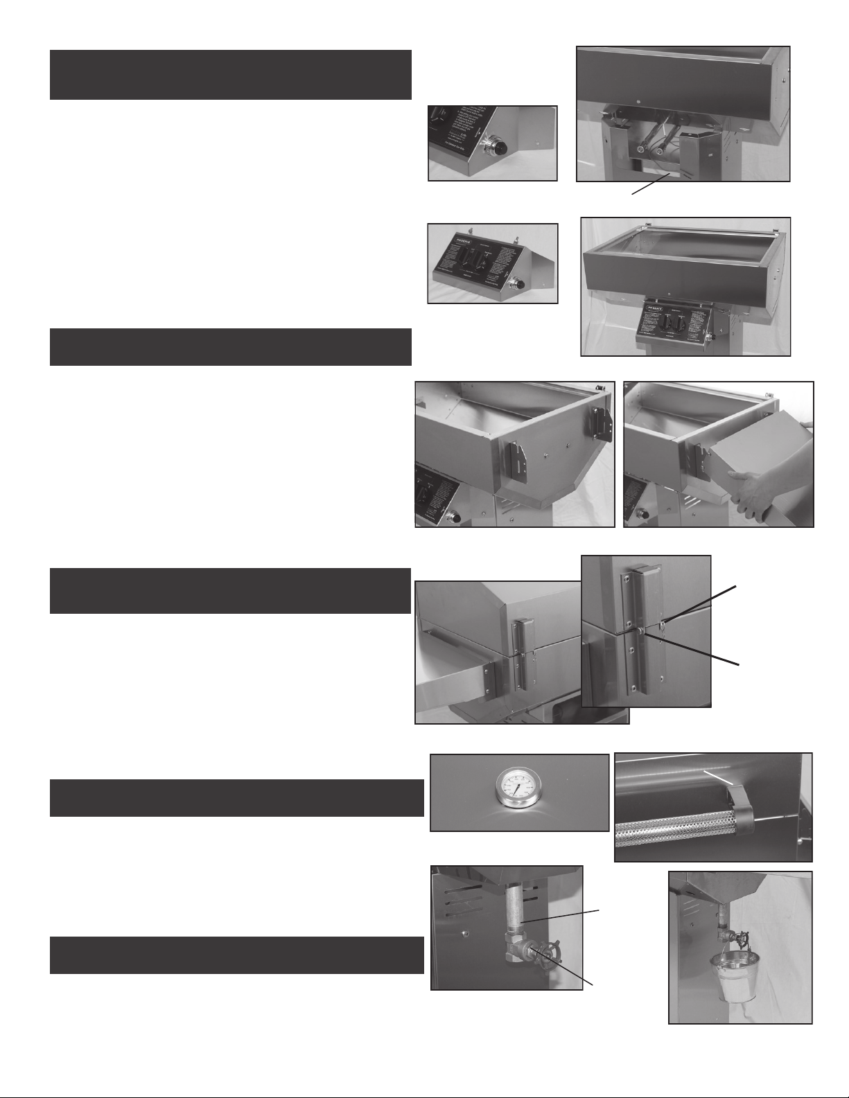
CONTINUE
Step 3: Attaching Control Panel to Grill Pit.
A. Thread on the push button to the igniter stem. (Fig. H)
B. Attach the igniter probe wire (preassembled at factory to the gas
collector box) to the electronic spark generator. (Fig. I)
C. Attach the control panel to the front of pit by pushing the two
threaded studs thru the holes in the bottom of the pit, making
sure the venture tubes fit over the valve orifices and secure with
2, flat washers and 2, 1/4” Kep nuts. (Fig. J-1)
D. Attach the bottom of the control panel to column using 2 1/4-20 x
1/2” hex head bolts , 4 flat washers and 2 Kep nuts. Press the 2
gas control knobs onto the valve stems. (Fig. J-2)
Step 4: Attaching Side Shelves
Fig. H
Fig. J-1
Igniter Wire
Fig. I
A. Remove white film from side shelves and grill.
B. Attach brackets to grill using bolts and kep nuts to each side of
your grill as shown in (Fig. K-1) Use 2 bolts and kep nuts per
bracket.
C. Place the left bottom shelf post into the left bottom bracket slot as
shown in (Fig. K-2). Gently spread the shelf apart to insert the
right bottom shelf post into the right bottom bracket slot. Secure
bottom posts with Nylock Nut—making sure nuts are snug but do
not restrict the movement of folding and unfolding of the shelf.
Note: Top posts on shelf do not use nuts.
Step 5: Lid Assembly to Fire Pit
A. Position the top and bottom hinges together and
complete assembly using the two (2) hinge pins and hinge
clips. (Fig. L)
B. With the lid open attach the handle to the lid using two 1/4-20 x 3/4” hex
bolts, flat washers, graphite gaskets, and Kep nuts. The gaskets are
positioned between the handle end caps and grill lid. (Fig. M)
C. Install the thermometer through the hole in the center of the lid.
And snug thermometer with thumb bolt. Do Not Over Tighten.
Fig. K-1
Fig. J-2
Fig. K-2
Hinge Clip
Hinge Pin
Fig. L
Graphite Gasket
Step 6: Install Drip Pan and Drain Valve
A. With the lid open, insert drip pan into place using the lift tabs on
each end. Line up the drain pipe with the hole in the pit bottom and
make sure the drain pipe extends out the bottom of the pit. Install
the brass valve onto the drain pipe, hand tighten only. (Fig. O)
(You may need to remove the valve occasionally for cleaning.
Hang the drain bucket on the brass valve and open valve. (Fig. P)
Step 7: Install Cooking Grid
A. Place the cooking grid into the grill.
Fig. N
Fig. M
Drain Pipe
Fig. O
9
Brass Valve
Fig. P
Page 10
GETTING TO KNOW YOUR
SDRIV4LDD
PHOENIX GAS GRILL
Heat Indicator
Sta-Kool
Stainless
Steel
Handle
Right & Left
Burner Controls
LP Hose Ring
Holder
Short Legs
LP Tank Holder
Lower Shelf
Bolts To Each
Leg
Grill Lid
Stainless Steel
Drop Down
Side Shelf
Electronic
Igniter
Drip Pan Drain
Valve
Grease Collector
Bucket
Gas Valve In Back
Of Control Panel
Long Legs
Dual Burner and
Gas Collector Box
INSIDE VIEW
Cooking Grid
REAR VIEW
Vents
Drip Pan
Vent Slide
Page 11

PEEL ALL LASER TAPE BEFORE ASSEMBLING
SDRIV4LDD Cart Assembly
Tools Required For Assembly:
7/16” Wrench, 7/16” Socket Wrench with Extension, 3/8”
Wrench.
CAUTION: Edges of some of the grill parts may be sharp,
use care when assembling grill.
CAUTION: While handling the grill head be very careful not
to damage the Venturi Tubes or the Ceramic Ignitor Insulator
which protrudes from below the grill.
CART HARDWARE
Carton contains the following components for the cart mounting:
Please check to be sure that all parts are included before proceeding. Contact your dealer or the factory if any parts are missing.
Long Legs 2
Short Legs 2
Lower Frame Brackets 2
Lower Tank Brackets 2
8" Rubber Wheels 2
Axle 22 1/2" 1
Axle Hitch Pins 2
LP Tank Fastener 1
1/4—20 Wing Nut 1
Complete View of Cart Assembly
1/4-20 x 1/2” Carriage 1
Hub Caps 2
Hose Retaining Ring 1
1/4-20x1/2” Truss Head 18
1/4-20x3/4” Hex Head 10
1/4-20 Kep Nut 28
10-24x1/2" Pn..Hd. 11
10-x24 Kep Nut 11
10-24 Nylon Lock Nut 8
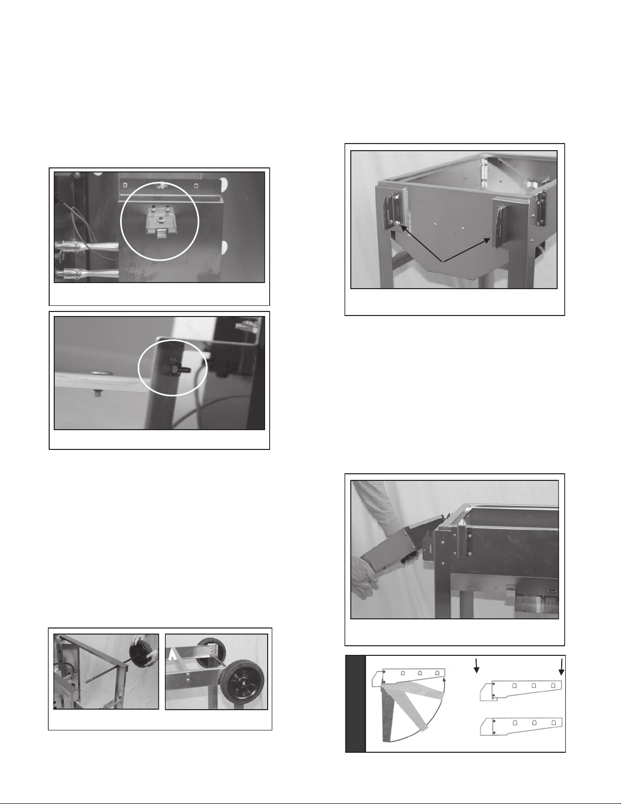
Step 1: Leg Assembly (Fig 2)
1. Tip the grill head bottom on end as shown in Fig. 2
(TIP: work on protected area such as carpet, tarp or one
of the boxes to protect grill finish.)
2. Attach the two long legs to the right end of the grill’s bot-
tom pit. Use two 10-24 x 1/2” Pan Head Bolts for each
leg. Insert bolts from outside of grill pit and fasten with 10
–24 kep nuts.
3. Flip the grill over and attach the 2 short legs to the left
side of the grill pit bottom. Use two 10-24 x 1/2” Pan
Head Bolts for each leg. Insert bolts from outside of grill
pit and fasten with 10-24 kep nuts. Note: When attach-
ing front legs make sure the control panel tab is
tucked behind the front legs as shown in (Fig. 3) The
valve stems must be seated properly in the venturi
tubes as shown in (Fig. 4) before tightening.
4. Flip grill upside down and attach the lower shelf brackets
to the front and back of the grill with four 1/4-20x1/2” Hex
Head Bolts for each bracket as shown in (Fig. 5).
5. Next attach the lower tank brackets from front to back to
the lower frame brackets as shown in (Fig. 6)Note: An-
gled edges face out.
6. Tighten all fasteners with wrench before moving on to
next steps.
FINGER TIGHTEN ALL BOLTS UNTIL
LOWER BRACKETS ARE ATTACHED.
Fig. 2
Hose Ring
Short Legs
FIG. 1
Lower
Cart Frame Bolts to
Each Leg
Long Legs
Fig. 3
Fig. 5
Fig. 4
Fig. 6
Page 12
Step 2: Installing LP Tank Fastener
1. Located on the underside of grill pit, mount the
LP tank fastener to the underside of the heat
shield with 2 10-24 Pan Head Blots as shown in
(Fig. 7).
2. Secure the LP tank fastener from the inside of
the heat shield with two 10-24 Kep nuts as
shown in (Fig. 8) and tighten with wrench.
Fig. 7
Fig. 8
Step 4: Installing the Drop Down Shelves
Mounting Bracket to Grill
1. Attach brackets to grill using bolts and kep nuts
to each side of your grill as shown in (Fig. 10)
Use 2 bolts and kep nuts per bracket.
Shelf Brackets
Fig. 10
Mounting Shelf to Bracket
2. Place the left bottom shelf post into the left bottom bracket slot as shown in (Fig. 11). Gently
spread the shelf apart to insert the right bottom
shelf post into the right bottom bracket slot. Secure bottom posts with Nylock Nut—making
sure nuts are snug but do not restrict the movement of folding and unfolding of the shelf.
Note: Top posts on shelf do not use nuts.
Step 3: Axle and Wheel Assembly
1. Install (1) axle hitch pin into the small end hole of
the axel. Slide (1) wheel onto the axle, hubcap
side out.
2. Slide open axle end through the short leg holes
and install remaining wheel, washer and hitch
pin. Install hubcaps after the cart bolts are completely tightened.
3. Stand grill upright to seat legs and tighten all
bolts and nuts making legs and frame rigid.
Note: Recheck all fasteners for tightness.
Fig. 9
Fig. 11
LOCK INTO PLACE
OPENING SHELF
Page 13
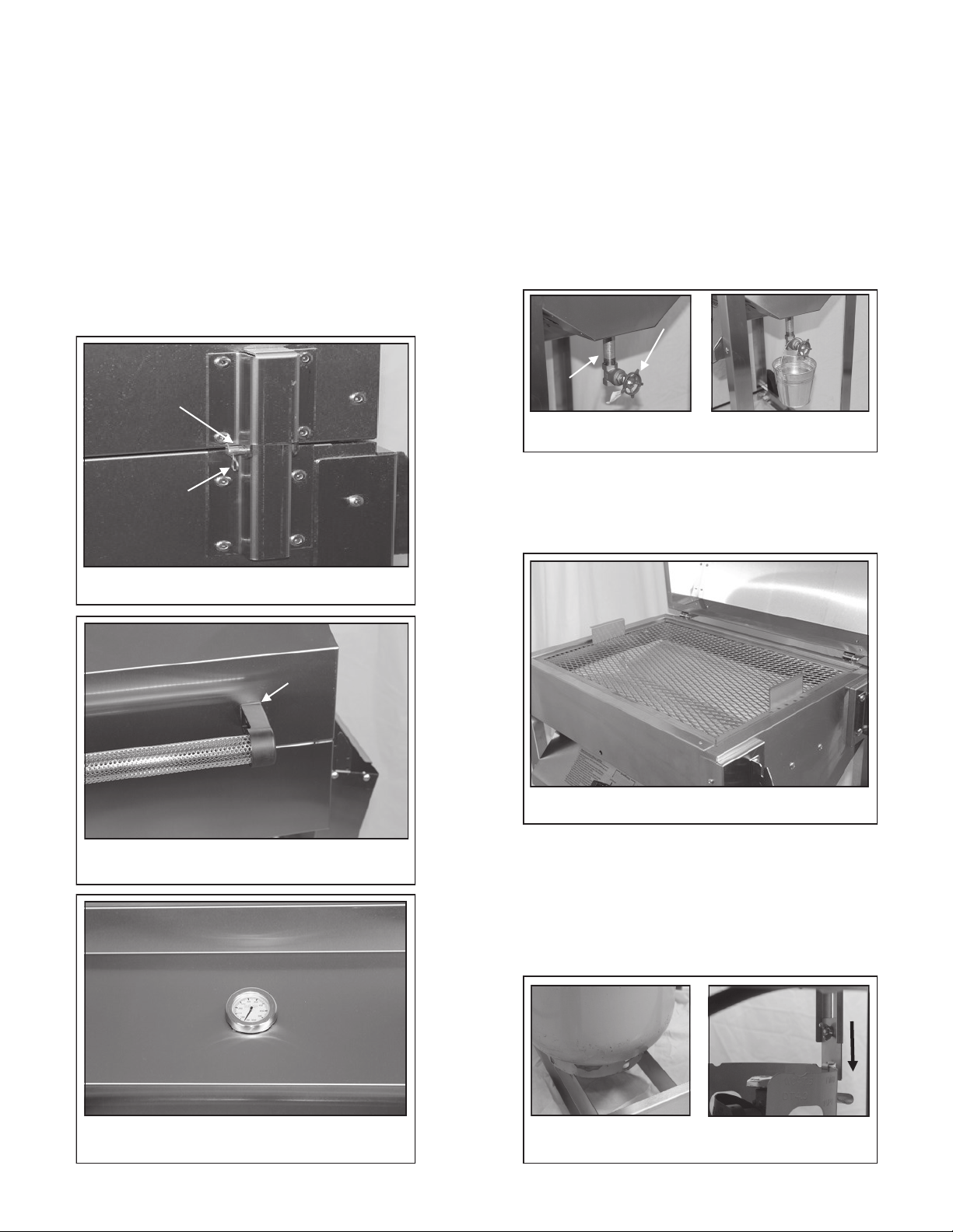
Step 5: Lid Assembly to Fire Pit
1. Position the top and bottom hinges together and
complete assembly using the 2 hinge pins and
hinge clips (Fig. 12).
2. With the lid open attach the handle to the lid
using two 1/4-20 x 3/4” hex bolts, flatwashers,
graphite gaskets and kep nuts. The gaskets are
positioned between the handle end caps and
grill lid. (Fig. 13)
3. Install the thermometer through the hole in the
center of the lid and snug the thermometer with
thumb bolt. (Fig. 14) Do Not Over Tighten.
Hinge Pin
Hinge Clip
Fig. 12
Graphite Gasket
Fig. 13
Fig. 12
Step 6: Install Drip Pan and Drain Valve
1. With the lid open, insert drip pan into place using
the lift tabs on each end. Line up the drain pipe
with the hole in the bottom of the pit.
2. Once drain pipe is in place resting in the bottom of
the pit thread the brass valve onto the drain pipe
hand tightened only. Note: You may need to
remove the valve occasionally for cleaning.
(Fig. 15)
3. Hang the drain bucket on the brass valve and
open valve. (Fig. 16)
Drain Pipe
Brass Valve
Fig. 15 Fig. 16
Step 7: Installing Cooking Grid
1. Place the mesh stainless steel cooking grid into
the grill as shown in (Fig. 17).
Fig. 17
Step 8: Installing & Locking LP Tank Into Place
1. Place LP tank into slots in support shelf on the
bottom of grill cart as shown in (Fig. 18).
2. Slide the LP tank lock down as shown in (Fig. 19)
and tighten wing nut to lock in place.
Fig. 18 Fig. 19
Page 14

Gas and LP Tank Connections
CONNECTING THE LP CYLINDER (Fig. R)
Install the gas cylinder in the back of your grill, with the open side of the
tank valve collar pointing towards the square hole in the tank enclosure.
Ensure that all hoses, fittings and regulators are properly protected from
heat and accidental damage. Hoses can be burned or chaffed if routed
improperly. (See Hose and Regulator, page 3). Be sure all burner con-
trol valves on the grill are turned “OFF”. To connect hose and regulator
to cylinder turn coupling nut clockwise as shown in diagram below (Fig.
R). (To remove the quick connect coupling nut, turn counter clockwise).
Your Phoenix Grill comes with a Type I connector, also known as a
“Quick Connect Valve” connection. It has a large plastic (coupling nut”
that screws onto the propane tank gas outlet. Note: Your Phoenix
Grill does not come with a propane tank. Therefore, be sure the
tank you purchase has this type of hook-up. Also, the cylinder you
use must be equipped with a listed overfilling protection device.
This can be identified by the triangular hand wheel. (See diagram
below and page 2 of these instructions).
Hand Wheel
Regulator
Tank
Coupling
Nut
Dust Cap
Fig. R
REMOVAL OF THE LP CYLINDER
1. Close the LP tank valve.
2. Unscrew the QCC-1 plastic nut BY HAND COUNTERCLOCKWISE (to the left).
3. Raise the tank locking bar
4. Lift cylinder off.
WARNING: If you exchange your LP cylinder, make
sure you get a similar tank in return.
Your exchanged LP cylinder must be equipped with a
QCC-1 or type-1 valve and an OPD (Overflowing
Prevention Device). Other LP cylinders may not be
compatible with your grill connection.
LP-GAS CYLINDER FILLING & HANDLING (Continued)
Air must be removed from a new LP cylinder before the initial
filling. Your LP dealer is equipped to do this.
The cylinder supply system must be arranged for vapor with-
drawal
Always keep and store cylinders in an upright, secure position.
Use this grill outdoors in a well-ventilated area. Do not use in a
garage, building, or any other enclosed area.
Storage of an outdoor cooking gas appliance indoors is permis-
sible only the cylinder is disconnected and removed from the
outdoor cooking gas appliance.
If the outdoor cooking appliance is not in use, the gas must be
turned off at the supply cylinder.
Cylinders must be stored outdoors out of reach of children and
must not be stored in a building, garage or any other enclosed
area.
LP GAS CYLINDERS SAFE HANDLING TIPS
Liquid propane (LP) gas is a petroleum product as are gasoline
and natural gas. LP gas is a gas at regular temperatures and
pressures. Under moderate pressure, inside a cylinder, LP gas
is a liquid. As the pressure is released, the liquid readily vaporizes and becomes gas.
LP gas has an odor similar to natural gas. Be aware of this
odor.
LP gas is heavier than air. Leaking gas collects in low areas
and prevents dispersion.
To fill, take the LP cylinder to your local authorized LP dealer,
or look up “gas-propane” in the yellow pages to find authorized
dealers.
A new LP cylinder must be purged before the first filling. Your
LP dealer is equipped to do this.
An LP cylinder must be transported, installed and stored in an
upright position.
LP cylinders should not be handled roughly.
Never store or transport an LP cylinder where the temperatures
can reach 125 degrees. Never leave an LP cylinder in a car on
a hot day.
Always close the LP cylinder valve before disconnecting the
tank or any other gas fitting.
Always close the LP Cylinder valve after using grill.
Do not use a damaged LP cylinder. Dented, rusty or a dam-
aged LP cylinder valve may be hazardous and should be replaced with a new one immediately.
LP-GAS CYLINDER FILLING & HANDLING
A qualified attendant, who fills the cylinder by weight, should
fill your LP cylinder at an authorized LP gas dealer. Improper filling is dangerous.
When transporting the LP cylinder be sure the plastic dust
cover is in place over the valve. This keeps the valve
threads free of dirt.
Do not handle the cylinder roughly.
Do not apply heat directly to the cylinder.
● Never fill the LP cylinder beyond 80% full.
● Do not store a spare LP gas cylinder under or near the
grill.
If this information is not followed exactly, a fire causing
death or serious injury may occur.
10
Page 15

Leak Testing and Lighting Your Grill
Leak Testing
LEAK TEST ALL GAS CONNECTIONS BEFORE USING YOUR GRILL.
DO NOT SMOKE WHILE LEAK TESTING.
DO NOT LEAK TEST WITH A MATCH OR OPEN
FLAME.
DO NOT USE A GRILL THAT IS LEAKING GAS.
YOU SHOULD TEST FOR GAS LEAKS EVERY TIME
YOU DISCONNECT AND RECONNECT A GAS FIT-
TING.
PERFORM A LEAK TEST EVEN IF YOUR GRILL WAS
DEALER OR STORE ASSEMBLED.
DO NOT IGNITE BURNERS WHEN LEAK TESTING.
LEAK TESTING
1. For LP models, leak test with a full propane cylinder.
2. For systems other than self-contained LP cylinders:
A. The grill and its individual shut-off valve must be discon-
nected from the gas supply piping systems during any
pressure testing of that system at test pressures in excess of 1/2 psi (3.5 kPa).
B. The grill must be isolated from the gas supply piping
system by closing its own manual shut off valve during
any pressure testing of the gas supply piping system at
pressures equal to or less than 1/2 psi (3.5 kPa).
1. Grill burner control valves should be turned off and the gas
turned on at source.
2. Apply soap solution to all gas connections.
To make soap solution, mix together equal amounts of
liquid detergent and water.
3. Soap bubbles will appear if there is a leak.
4. Tighten the connection to make proper seal. And recheck for
soap bubbles.
If you cannot stop a gas leak by tightening, turn gas
supply off. Take leaking joint apart, clean it, reconnect and test again. If leak persists, contact the dealer or gas utility.
A gas system MUST be tested yearly, or whenever
the LP cylinder or any other gas system part is replaced.
Lighting Your Grill
ALWAYS OPEN GRILL BEFORE LIGHTING THE BURNER.
DO NOT LEAN OVER AN OPEN GRILL. KEEP YOUR
HEAD AND BODY AT LEAST ONE FOOT AWAY WHEN
LIGHTING THE GRILL.
IF BURNER DOES NOT LIGHT, IMMEDIATELY TURN
BURNER CONTROL KNOBS TO OFF. WAIT FIVE
MINUTES TO LET GAS CLEAR BEFORE YOU TRY
LIGHTING AGAIN.
LIGHTING
1. Open Lid. Examine the interior to be sure it appears normal.
2. Turn burner control knobs to OFF position.
3. Turn gas ON at LP tank or supply. Wait 5 seconds for regulator to set itself.
4. Turn either burner control knob to HIGH and rotate the ignitor knob CLOCKWISE several times. One half of the burner
should light. Turn the other burner control knob to HIGH and
the other half of the burner will light automatically.
5. The burner flame should be a hard blue cone with a minimum amount of yellow flame, although some yellow dust
flicks may occur.
BURNER
FLAME
GOOD FLAME BAD FLAME
6. Close the grill lid and pre-heat the grill for five to ten minutes
before cooking.
WARNING: If burner fails to light, turn control knobs OFF
and wait five minutes for gas to clear and try lighting procedure again.
To light burner manually: With the grill lid opened, open valve
at propane tank or natural gas supply. Turn the right burner
control to “HIGH” and insert lit match or lighter into match hole
located in the lower section of the fire pit and to the right of the
control panel.
To Extinguish your grill: Turn each burner control knob to
OFF position. Turn gas supply OFF at the source.
YELLOW
BLUE
YELLOW
BLUE
11
Page 16

Maintenance
Annual Maintenance
After a period of nonuse or to keep your grill in top
operating condition, you should perform the following maintenance procedures to keep the grill ready for instant use and for
your safety.
Do not obstruct the flow of combustion and ventilation air.
Clean inside the grill head. Remove the burner/venturi as-
sembly and cover the valve orifices with a piece of aluminum
foil to keep out dirt. Brush inside bottom and sides with a stiff
wire brush to remove built-up grease and debris. Be careful
not to damage the Ignitor or Collector Box.
Test the Ignitor for a good spark. (See Rotary Spark Ignitor
System in the General Maintenance section.)
The stainless steel burner may be brushed lightly with a stiff
laundry brush. Any clogged flame holes may be opened using a thin wire. Use the supplied venturi cleaning brush or a
bottle brush, pipe cleaner to clean out the venturis. (See
Flashback in General Maintenance.)
Clean the Control Panel, Side Shelf Supports, Lid Handle
Spacers, Lower Cart Frame, Posts with a mild detergent
soap and warm water solution. For the column use a mild
detergent soap and water, Windex is also great to clean the
column and grill lid facing. Do Not Use cleaning agents
such as bleach, powdered cleansers, steel wool pads or
caustic solutions like oven cleaners because they will
damage the surfaces.
Occasional white oxidation on the exterior of your grill head
and lid may be washed off with mild soap and warm water.
Severe weathering of the grill head and lid can be remedied
by lightly sanding or rubbing with steel wool. Then it can be
recoated with a high quality heat resistant paint similar to
MHP’s BF-1 Paint, available in spray cans from your dealer.
Inspect the hose and gas fittings. Remember to leak check
every time you disconnect and reconnect a gas fitting.
Keep the ventilation openings of the LP cylinder enclosure
free and clear from debris.
General Maintenance
Flashback
In some areas of the country, spiders and other insects build
nests, lay eggs and spin webs in the grill’s venturi tube or valve
orifice. This obstructs the full flow of gas to the burner. Some
gas backs up resulting in a “Flashback” - a fire in the venturi
behind the control panel which could cause serious bodily injury
or damage to your grill.
Orifice
To remove spider webs and/or other obstructions, you must
clean out the venturis. This should be done routinely if the
grill has sat idle for extended periods. Also, if you live in an
area where spiders are plentiful, you should clean the venturis often, especially in the fall when there is an increase
in egg sack production.
To clean, be sure the grill is cold. Open lid and remove the
cooking grids, the briquettes and the briquette grate.
1. Remove the burner clip holding the burner in place.
2. Lift burner and venturi assembly out. With supplied cleaning brush, a pipe cleaner or a flexible wire, clean out the
venturi tube.
3. Remove hex head orifice with a 3/8" wrench. Clean Orifice
hole and inner part of the valve with a toothpick. Be careful
not to enlarge the orifice hole.
4. Check orifice receptacle in valve body.
When finished cleaning reassemble the complete unit.
Unscrew and
Clean Orifice
Air Shutter
Spider Webs
Inside Venturi
Lift Out
Warning: Check the hose before each use of the grill for nicks,
cracking, abrasions or cuts. If the hose is found to be damaged
in any way, do not use the grill. Replace using only MHP authorized replacement hose.
Clean Out
Venturi Tube
Venturi Brush
12
Page 17

Maintenance
General Maintenance
Rotary Spark Ignitor System
If you experience an occasional “No-spark-No light” condition here’s a check list to troubleshoot the problem.
1. Inspection. WITH GAS OFF, position a mirror in front of the
collector box and rotate the ignitor knob several times. Observe
the condition of the spark. (Low light conditions are the best for
seeing the spark.)
Mirror
Collector Box
B. Check spark. Pull the connector wire from the collector box
(see “X” Fig. S). Bring wire to bottom or top of control panel,
hold about 1/8" away and operate the ignitor. Check for spark.
If there is no spark replace the Rotary Ignitor. If there is a
spark the Rotary Ignitor is OK, but the Collector Box/Electrode
assembly should be replaced (the ceramic insulator could be
cracked).
B. Hold Connector
1/8” From Panel
Bottom.
Rotate Ignitor
Knob
C. Check Knob, confirm quality of the electrical ground at the
Rotary Ignitor. Remove the knob, loosen and retighten the
mounting screws.
A. If there’s a good spark, but the grill
won’t light, gas may not be flowing to the
burner and into the collector box. The gas
orifice or the venturi tube may be blocked.
To clean, follow “Flashback” instructions.
B. If a weak spark arcs down around the
ceramic insulator, the insulator should be
cleaned. The insulator has a coating of
grease or it is wet. Use an old tooth brush
to break up the conductive electric path.
2. If there is no spark in the
collector box.
A. Check the wire connections
at the ignitor and electrode
Mechanism
WD
40
Lubricate
Ignitor
under the grill. Lubricating
(use WD-40 or equivalent)
the star wheel and tension
spring of the ignitor will help
connection contacts and im-
Connector
prove operation.
A. GOOD SPARK
B. WEAK SPARK
Check Connection
Fig. S
“X”
Electrode Replacement or
Adjustment
The electrode inside the
collector box is pre-set for
optimum spark. The tip is
1/8" from inside surface of
the collector box.
Check the gap of the new
part before installing. Loosening and tighten the two
jam nuts will move the electrode tip, set at 1/8".
1/8”
Gap
Collector
Box
Electrode
Ceramic
Insulator
Ignitor
Wire
13
Page 18

Cooking Tips
Cooking Tips For Your
New Phoenix Grill
Your new Phoenix eliminates flare-ups because the cooking
surface is shielded from direct flame contact by a drip pan. For
best results we recommend that all preheating, grilling,
smoking, baking and steaming be performed with the lid
closed!
WARNING: ALWAYS LIGHT YOUR GRILL WITH THE
LID OPEN.
GETTING STARTED
Before you use your grill for the first time be sure to read and
thoroughly understand all grill safety, lighting, locating, operating and maintenance procedures found in this book.
We recommend you “break-in” your grill by cooking the
first 2 or 3 times at medium or low temperature settings.
This allows the drip pan to “season/break-in”. Please note:
as long as the grease can flow into the grease bucket it is
not necessary to clean the drip pan after each use. Clean
as needed or approximately every 10 uses.
After each use, we recommend you turn the control knobs
to “HIGH” (with the lid closed) and run the grill for approxi-
mately 10 minutes. This will allow the accumulated fats and
greases to cook off, and avoid a possible flare up on the
next use. HINT: The fats and greases are cooked off when
no more smoke is flowing from grill vents.
We recommend cleaning the cooking surface (cooking grid)
before each use and before you light the grill. Simply run a wire
brush front to back and side to side across the diamond shaped
cooking surface. This can be performed with the cooking grid in
place or you can remove the cooking grid for cleaning.
The drip pan valve should be kept open while your grill is
in use. This allows the grease that drips from your food to con-
tinuously drain into the grease catch bucket. If you are cooking
a small quantity of food or food with very little fat, you may not
notice any grease collecting in the grease bucket. However, if
you notice grease accumulating in the drip pan but is not running into the grease bucket, then either your drain valve is not
open or the drip pan pipe is clogged. Don’t attempt to clear the
clog while the grill is hot! Wait until the grill has cooled, remove
the cooking grid and run a stick down the drain pipe until the
clog is cleared.
The only time the drip pan drain valve should be closed during
grill use, is when you are steaming or smoking with liquid
smoke. See below for steaming and smoking instructions.
The following grilling steaming, smoking and baking tips are
provided as helpful guidelines. With experience you will find the
cooking times and temperature control settings that best suit
your taste. Please refer to page 15 for suggested cooking
times.
GRILLING
Pre-heat your grill with both controls on “HIGH” for 15 minutes.
If you are cooking hamburgers or steaks we recommend that
you leave the temperature controls on the “HIGH” setting. Re-
member, for best results, cook all your foods with the lid closed.
If you are cooking chicken, turkey, roasts, hot dogs or sausages
we recommend that after preheating your grill on “HIGH”, turn
both controls on the “MEDIUM” settings (half way between the
high and low setting). To keep food warm, or to further slow the
cooking process, you may try running only one side of the grill
and warming or cooking on the opposite side. Or you may try
cracking the lid (with a wood spacer) to let out heat.
BAKING
Pre-heat with both controls on “HIGH” for 10 minutes. Then set
your controls to the following setting that most closely matches
the temperature you want to achieve.
(Hint: the lid thermometer will help to more accurately set you
control).
Low Setting 350° Degrees to 400° Degrees
Middle Setting 400° Degrees to 450° Degrees
High Setting 450° Degrees to 500° Degrees
SMOKING
Caution: Before you proceed, make sure that your grill is on a
solid level surface. Check to see that your drip pan is relatively
clean. Smoking or steaming with a dirty drip pan can affect the
taste of your food. To clean your drip pan, simply unscrew the
drain valve and lift out the drip pan. Never attempt to clean the
drip pan while the grill is hot or if the grill is in use. A putty knife
or scraper works well for cleaning out the drip pan.
WOOD CHIP OR CHUNK SMOKING
Place the desired amount of wood in a wood chip container.
You can fabricate your own container(s) by folding heavy gauge
aluminum foil into an open square or purchase a MHP stainless
steel smoker box (part #SDSSST) from your Local Dealer.
Place one or more containers directly on top of the drip pan
located under the cooking grid. Do not place the container in
the middle of the drip pan. For best results place the container
halfway between the center and the edge of the drip pan. Heat
the grill on “HIGH” for 30 minutes, or until you detect smoke,
before you place your food on the grill. Cook to desired taste.
14
Page 19

Cooking Tips
LIQUID SMOKE GRILLING
Make sure your drip pan is relatively clean, see page 14 for drip
pan removal cleaning. Close the drip pan drain valve and fill the
drip pan with water (be sure not to overfill your drip pan). Add
several ounces of liquid smoke. Experience will dictate how
much liquid smoke is required to suit your taste. Heat the grill
with both controls on “HIGH” for 20 to 25 minutes. Keep controls on the “HIGH” settings and cook to desired taste. Add
more water and liquid smoke if you are cooking for an extended
period of time. Do not attempt to move your grill with water in
the drip pan, and wait until your grill has cooled before draining
out any remaining water.
STEAMING
CAUTION: Before you proceed, make sure that your grill is on a
solid surface. Check to see that your drip pan is relatively clean,
see “smoking” instructions for drip pan removal and cleaning.
Close the drip pan drain valve and fill the drip pan with water )
be sure not to overfill). Heat the grill with both controls on
“HIGH” for 20 to 25 minutes. Keep controls on the “HIGH” set-
ting and cook to desired taste. Steaming is good for foods as
oysters, clams, lobsters, and shrimp, etc. Do not attempt to
move your grill with water in the drip pan, and wait until your
grill has cooled before draining out any remaining water.
The following quality MHP accessories are designed to make
your smoking experience more convenient and enjoyable. See
these products and a complete list of accessories for your new
Phoenix grill on pages 18 and 19.
Stainless Steel
Smoker Box
COOKING TIMES
A Quick Reference
Control Setting
Chicken 3 lb. Whole
Chicken
Chicken Legs or
45-60 Minutes LOW
Thighs
Pork Chops 1 Inch Thick 15 Minutes Each
Italian Sausage 40 Minutes MEDIUM
Pork Sausage Patty 8 Minutes Each Side MEDIUM
Pork Ribs 60 Minutes MEDIUM
Prime Rib 2 1/2 Hours (Use
Vegetables All 30 Minutes LOW
Biscuits Canned 7 Minutes Each Side LOW
90 Minutes LOW
MEDIUM
Side
MEDIUM
Meat Thermometer)
15
Page 20

TROUBLE SHOOTING GUIDE
If you are having difficulty with your grill, follow this guide to solve some common problems.
Problem #1: BURNER(S) WILL NOT LIGHT OR THE GRILL
DOES NOT GET HOT ENOUGH.
PROBABLE CAUSE SOLUTION
A. Propane Cylinder Almost Empty. Have Propane Cylinder Filled.
B. Propane Cylinder Valve Not On. Turn Valve On. Turn Counter-Clockwise to Open.
C. Kink In The Gas Hose. Reposition The Propane Cylinder To Straighten The Hose.
D. Burner Holes Clogged. Clean With Small Wire or Round Toothpick and Sire Brush the Entire
Burner. See “Care and Maintenance” Section For Further Instructions.
E. Venturi Blocked. Clean Venturis. Refer to “Venturi Cleaning” Section
F. Venturis Not Sealed. Refer to “Prior to Use” Section
G. Orifices In Valve Outlet Plugged. Clean Orifices (small hole in valve outlet).
H. Regulator And/Or Valve Defective. Take Complete Hose, Valve and Regulator Assembly to a Servicing LP
Gas Dealer for Inspection.
I. Ignitor Not Working. Check For Proper Electrode Gap. Make Sure All Wires Are Connected
and None Broken. Check Ceramic for Cracks.
Problem #2: FLASHBACK (fire in venture or control panel area).
IF FLASHBACK SHOULD OCCUR, SHUT CONTROLS OFF THEN TURN VALVE OFF
AT PROPANE CYLINDER.
PROBABLE CAUSE SOLUTION
A. Venturi Blocked Clean Venturis. Refer To “Venturi Cleaning” Section.
B. Venturis Not Sealed. Refer To “Prior To Use” Section.
C. Valve Out Of Alignment. Adjust Valve So The Valve Outlets Are Pointing Straight Into
The Venturis.
D. Burner Holes Clogged. Clean With Small Wire or Round Toothpick and Wire Brush
the Entire Burner. See “Care and Maintenance” Section
For More Information.
E. Windy Day Shield Grill From The Wind.
16
Page 21

Parts Information
QUANTITY PART NO. DESCRIPTION
1 SDBASE Grill Base (SDWELDD & SDRIVDD)
4 KKWL3 Locking Casters (SDWELDD & SDRIVDD)
1 PFCFT Column Front (SDWELDD & SDRIVDD)
2 PFCSD Column Sides (SDWELDD & SDRIVDD)
1 SDHOOD Hood (Lid) (SDWELDD)
1 SDRVHOOD Riveted Hood (Lid) (SDRIVDD & SDRIV4LDD)
1 GGSH Stainless Steel Handle
2 GGSHC Handle End Caps
2 GGSHG Handle Graphite Gaskets
1 GGTG4 Temperature Gauge
1 SDPIT Fire Pit (SDWELDD)
1 SDRVPIT Riveted Fire Pit (SDRIVDD & SDRIV4LDD)
2 PFHH Hood (Lid) Hinge
2 PFPH Fire Pit Hinge
2 SDHP Lid Hinge Pins
1 SDCV-430 Vent Control
2 PFDPBKT Drip Pan Bracket
1 SDFABCP Control Panel (SDWELDD & SDRIVDD)
1 SDRIVCONT Control Panel (SDRIV4LDD)
2 SDPF80-5 Control Knobs
1 SDCPLBL-P Control Panel Label (SDWELDD & SDRIVDD)
2 PFSB-A Right Side Shelf Brackets
2 PFSB-B Left Side Shelf Brackets
2 SDSSDD Stainless Steel Side Shelves
1 SDSUP Column Support (SDWELDD & SDRIVDD)
1 OBS-SD Stainless Steel Burner
2 SDV34 Venturi Tubes
2 GGLPP1 Burner Hitch Pins
1 IG5 Gas Collector Box
1 GGEIB Electronic Ignitor
1 GGEIBPB Ignitor Push Button
1 HHVLV28SD Propane Gas Grill Valve (For Propane Models)
1 HR6B Propane Gas Hose and Regulator (For Propane Models)
1 HHVLV32SD Natural Gas Grill Valve (For Natural Gas Models)
1 ASCPL1 12’ Quick Disconnect Hose (For Natural Gas Models)
1 SDSSDT-A Cast Aluminum Drip Pan
1 SDDV Drip Pan Drain Valve
1 SDGB Grease Collector Bucket
1 VTC Venturi Tube Cleaning Brush
2 GGWL 8” Wheel (SDRIV4LDD)
2 GGAWP Axle Wheel Pin (SDRIV4LDD)
2 GGHC Hub Cap (SDRIV4LDD)
17
Page 22

UPGRADES AND ACCESSORIES
FOR ADDED
VERSATILITY, CONVENIENCE AND OUTDOOR
COOKING ENJOYMENT.
Infrared Burner
#PFMGSEAR
State-of-art cooking system gives you time saving grilling at
high temperature in seconds. The overall intense heat seals in
meat juices for better flavor. Stainless Steel construction and mounts
easily to the side of you grill. Our patented reversible cooking grid included. Electronic ignition for fast starts. Removable drip pan for easy
clean-up. 22,000 BTU’s and is available in Natural or Propane Gas.
Heavy Aluminum Griddle
#SDAG
Heavy-duty griddle perfect for
breakfast French toast, eggs, bacon,
etc. 16" L x 12" W
Fish Spatula
#FS1
Stainless steel fish spatula with
genunie rosewood handle.
18-1/2" L x 10" wide spatula
Stainless Steel Smoker Box
#SSST
Stainless steel smoker box with cover. For
use with all grills. Insert moistened wood
chips for your favorite smoke
flavor. 8-3/4" L x 3-1/2" W x 1-1/2" D
Super Flipper
#SF1
Stainless steel super flipper. The
ultimate spatula tool, specially
curved for perfect flips every time.
18" overall length.
18
Anodized Aluminum Grid
#SDGRIDS
Reversible rust-free anodized cooking
grid that heats up faster and spreads
heat more evenly. Wide-ribbed side for
steaks, chops, etc. and flat side for cook-
ing delicate foods. 161/2" x 8"
Wire Cleaning Brush
#WB3B
Brass bristle brush with scrapper, wood handle and leather
tong for hanging.
18" overall length.
Page 23

Secondary Cooking
Surface/Warming Rack
#SDSCS
More than a typical warming rack.
This elevated surface cooks at
lower temperatures for added
flexibility. 24” W x 8” D x 4 1/4” H
Roast Holder
#RR3
Holds roasts, ham, fowl so heat
circulates evenly around meat
for thorough balanced cooking.
Made of nickel-plated steel.
15-1/4" L x 10-1/2" W
Rib/Potato Rack
#RR2
Chrome plated accommodates 6
racks of ribs and 6 poatatoes.
12" L x 7-1/4" W
Ceramic Pizza Stone
#PZT13
For an evenly cooked pizza and a
crispy crust. The stone sumulates
the hearth of a pizza oven. For
cean-up, just wipe it off. 13” round
Stainless Steel Scraper
#SDDPS
Unique rust-free designed drip
pan scraper for Phoenix and
Hollard Grills. Hanging hole for
easy storage.
Skewer Set
#SR7B
6-piece chrome plated skewers
designed so food does not
rotate.
19-1/2" long.
Mid-Length Cover
#GGCVPREM
Premium quality polyester lined
vinyl with E-Z on/off Velcro tabs.
Fits Scottsdale Grill with two (2)
side shelf.
60" left to right, 20" front to back
and 24" top to bottom.
19
Stainless Steel Cleaner
#SCC
Specially formulated for MHP
stainless steel grills.
8 oz. bottle.
Full-Length Cover
#CV4PREM
Premium quality polyester lined vinyl
with E-Z on/off Velcro tabs. Fits
Scottsdale Grill with two (2) side
shelf.
60" left to right, 20" front to back and
42" top to bottom.
Page 24

Professional Quality Products For Your Backyard
5565 North 124th Street • Butler, Wisconsin 53007
Phone: 262.781.4657 • 888.761.4657
Fax: 262.781.3965 • 888.781.3965
Email: info@profiregrills.com
Produced by ProFire Grills
A Division of Modern Home Products Corp.
©2012 Modern Home Products Corp. MHP configuration, SearMagic, ProFire Grills are registered trademarks of Modern Home Products Corp.
Because of constant product improvement, ProFire Grills reserves the right to change specification without notice. 3/17
Web Site: www.newphoenixgrills.com
 Loading...