

Page 1
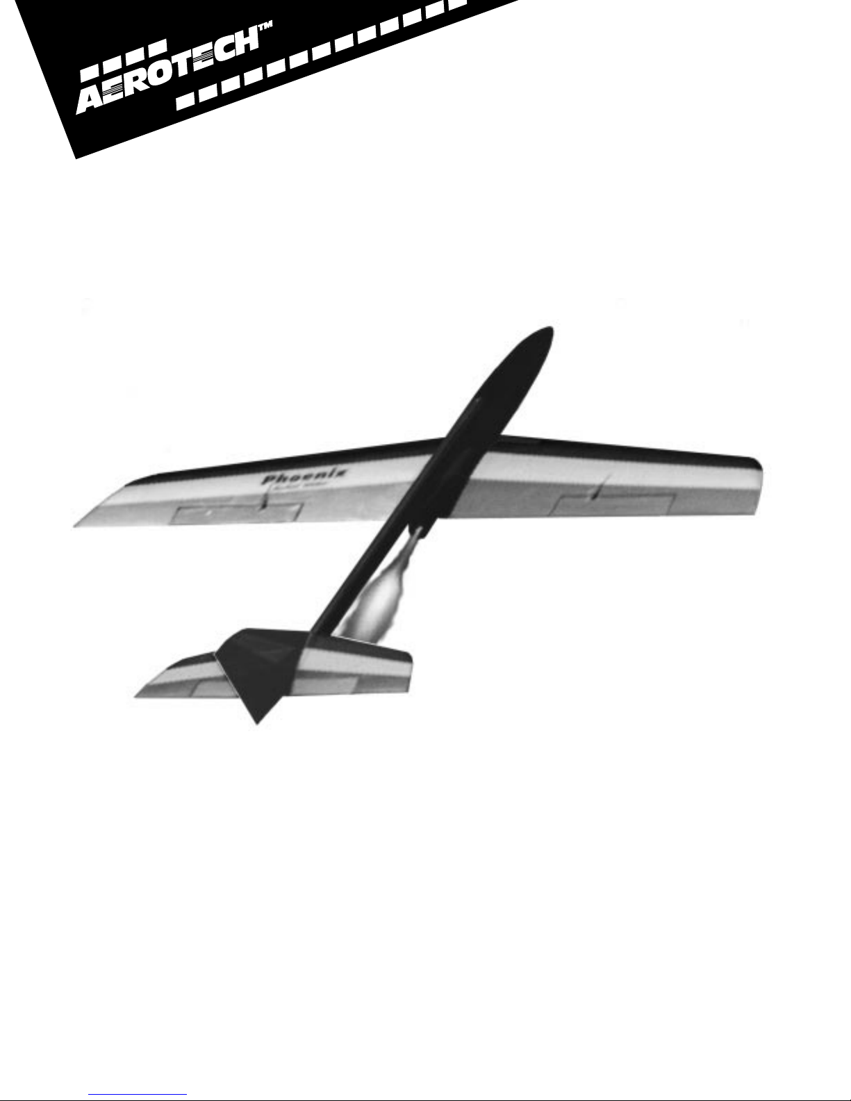
Phoenix
™
Rocket Launched
R/C Aerobatic
Glider
Assembly and Operation
Manual
CONSUMER AEROSPACE
© 1991 AeroTech Inc.
Page 2

Warning!
Read This Carefully!
The radio controlled model that you will build from this kit and the AeroTech motors and propel-
lants that you will use are not toys!
This model is not intended to be flown by inexperienced pilots.
If incorrectly built, mishandled or misused, they are capable of bodily harm and property damage. Therefore,
it is your responsibility to correctly build this kit, to install all components carefully and accurately, and to
test and fly this product in accordance with all safety standards prescribed by the Academy of Model Aeronautics Safety Code. We strongly suggest that you join the AMA and become fully and properly insured before
using these products. If you require technical, construction or flying assistance, contact your local hobby
shop or the AMA to locate experienced instructors.
AeroTech certifies that it has exercised reasonable care in the design and manufacture of its products. As we
cannot control the storage and use of our products, once sold we cannot assume any responsibility for product storage, transportation or usage. AeroTech shall not be held responsible for any personal injury or property damage resulting from the handling, storage or use of our product. The buyer assumes all risks and liabilities therefrom and accepts and uses AeroTech products on these conditions.
No warranty either expressed or implied is made regarding AeroTech products, except for replacement or
repair, at AeroTech ’s option, of those products which are proven to be defective in manufacture within one
year from the date of original purchase. For repair or replacement under this warranty, please contact
AeroTech. Proof of purchase will be required. Note: Your state may provide additional rights not covered by
this warranty.
AeroTech, Inc. Academy of Model Aeronautics
1955 S. Palm St. 1810 Samuel Morse Dr.
Suite #15 Reston, VA 22090
Las Vegas, NV 89104 (703) 435-0750
(702) 641-2301
(800) 752-8018
Table of Contents
Introduction................................................................................................1
About Phoenix ...........................................................................................2
Before You Begin Construction.....................................................................3
Wing Construction......................................................................................6
Tail Construction.......................................................................................16
Fuselage Construction...............................................................................17
Final Assembly.........................................................................................21
Launcher Assembly...................................................................................27
Finishing..................................................................................................31
Flying Phoenix .........................................................................................31
Appendix A: Safety..................................................................................36
Appendix B: About Rocket Motors.............................................................38
Appendix C: Parts Layout .........................................................................40
Appendix D: Parts List ..............................................................................41
Appendix E: Launcher Base.......................................................................42
Appendix F: Suppliers ..............................................................................43
Phoenix, AeroTech, Reloadable Motor System, RMS, Mantis, Interlock, White Lightning, BlackJack, BP4d and Easy Reference are trademarks of Aerotech Inc. All other trademarks are property of their respective owners.
Page 3

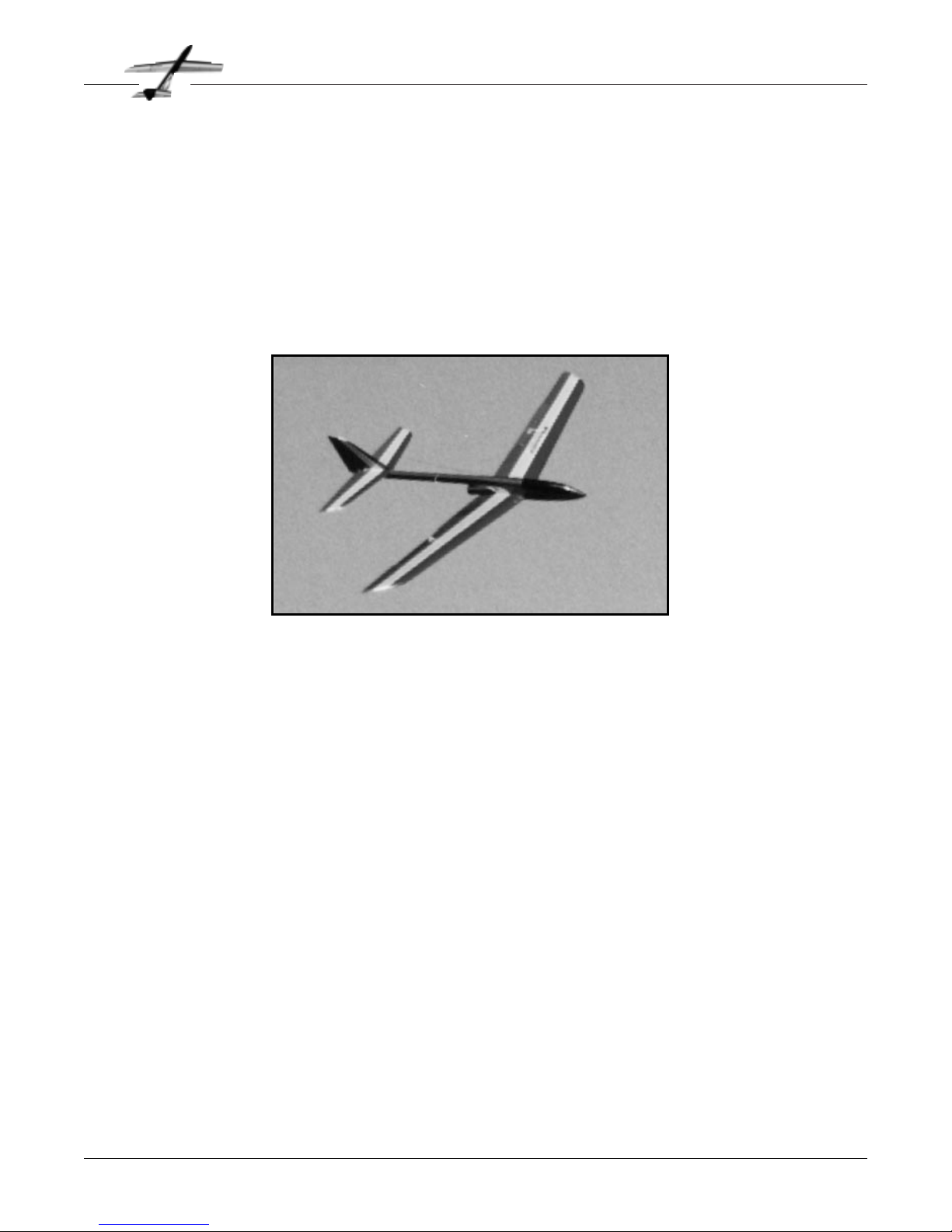
Phoenix
Page 1
Introduction
C
ONGRATULATIONS! You are now embarking
on a new and exciting era in model aviation,
high performance rocket gliders! Phoenix is the
first of a new generation of rocket gliders from
AeroTech and it will provide you with many
exciting and satisfying flights. Thank you for
choosing Phoenix!
Phoenix is the culmination of many years of
flight and design experience with model airplanes, model rockets and with rocket gliders.
Designed for the intermediate to advanced
level pilot who wants high performance, both
in the launch and in the glide phases of flight,
Phoenix is a revolutionary design. You’ll have a
new class of model, exciting and different,
unlike anything you currently have in your
model airplane hangar.
What do we mean when we describe Phoenix
as revolutionary ? By using extensive computer
aided design, from the custom airfoils to the
overall configuration, Phoenix uses the latest
breakthroughs in aerodynamics to achieve
these unique design goals:
• smooth, precise handling on launch
• low drag for outstanding launch performance
• ability to withstand the high speed and
acceleration of launch
• high L/D and large speed range during
glide for easy thermalling
• fully aerobatic during glide
• light weight and ease of construction
• maximum efficiency through an integrat-
ed rocket design
You’ll be able to experience all of these objectives for yourself as you build and fly Phoenix.
We’ve carefully laid out the plans, detailed the
instructions and chosen the wood and other
components so that your Phoenix can be as
good as ours and you can have as much fun as
we have had.
If you are an intermediate level pilot, you’ll be
able to immediately enjoy the high performance characteristics of Phoenix. By intermediate level, we mean someone who has previously built and successfully flown aileron
equipped aerobatic RC models. While Phoenix
is not difficult to fly for a pilot who has already
flown several other planes, it is not for the
novice or beginner pilots.
P
HOENIX does not require that you have pre-
vious experience with model rockets. You
just have to remember to follow some common
sense safety rules. Just like it is a good idea to
keep your hand out of a spinning prop, Phoenix
should be launched only from its launcher, and
only with a remote electrical ignition system.
Please read the flying and safety sections in
this manual for further details..
We ask that you follow the instructions as written, because after many prototypes and much
experimentation, we’ve learned what tools,
techniques and components work best. While
Phoenix is easy to build because of the work
we’ve put into it, the design is integrated, so
that every detail contributes to the overall performance and changing one part of the design
will impact the performance in other areas.
For maximum performance and safety, you
must:
• Build Phoenix as described
• Install a fully working, tested and legal
radio system
• Follow the AMA safety code, and the
Rocket Glider safety code, as described
in this manual
• Always use the recommended rocket
motor reloads from AeroTech
• Test fly the Phoenix as described in this
manual, and lastly
• Have a great time flying Phoenix!
We know that you’ll enjoy your Phoenix Rocket
Glider and you will have many exciting flights.
We look forward to hearing from you: your
comments, suggestions and experiences.
Included in this kit is a product registration
and evaluation card. We’d appreciate you completing it so we may do a better job in future
rocket glider kits. We always look forward to
your comments.
Thanks again for choosing Phoenix!
Page 4
Phoenix
Page 2
About Phoenix
Integrated Rocket Motor
P
HOENIX has a carefully integrated rocket
motor for both good performance and good
behavior on boost. For example, the placement
of the rocket thrust line is critical for a stable
boost. With Phoenix’s high thrust to weight
ratio (5:1 for Phoenix versus 1.5 to 1 for a hot
power plane), Phoenix’s motor thrust line had
to pass through the CG or the model would try
to loop violently on launch. Phoenix’s motor is
located as close as possible to the model’s CG
to reduce the amount
of CG movement as
fuel is burned. Finally,
the motor mount
angle on Phoenix was
carefully tested with
over 100 flights to
minimize drag while
providing easy access
to the motor for
reloading.
Computer Designed
Airfoil
P
HOENIX uses a custom computer designed
airfoil, the BP4d™, for maximum boost and
glide performance. To achieve the best overall
results, the main design goal for the airfoil was
a significant reduction in drag. The BP4d
design did this, and is a significant improvement over sections such as the S3021, a common RC sailplane airfoil. When compared with
the S3021, the BP4d has 33% lower drag at
launch speeds and 5 to 15% lower drag during
typical gliding flight, with only a slight
decrease in maximum lift. As a result , Phoenix
has a very wide speed range in glide, and
retains a good glide ratio at high cruising
speeds. Also, the Phoenix airfoil is slightly
thicker, for better strength and for adequate
room for aileron servos. With its substantially
thicker aft section, the ailerons are thicker,
reducing the possibility of flutter at high flight
speeds.
Two Aileron Servos
P
HOENIX has an aileron servo installed in
each wing panel for several important reasons. First, by locating the servos away from
the center section of the wing, where the flight
loads are the greatest, less structural reinforcement is required to maintain the designed
strength of the overall wing. The wing is
stronger and actually lighter by having two servos outboard in the wing instead of one in the
center surrounded by extensive reinforcements! Second, by moving the servos into the
wings, closer to the ailerons, the result is stiffer
linkages which are much less prone to flutter at
high speeds, such as during launch. Finally, a
dedicated servo for each aileron gives more
accurate control for
precise roll authority,
as expected by experienced pattern flyers. While this is not
essential for a sport
plane such as
Phoenix, once we
started using the two
ailerons and enjoyed
the roll response, we
couldn’t give it up.
Offset Vertical Tail
O
NE unique feature of Phoenix is its offset
vertical tail. If you haven't already noticed,
the tail is not on the centerline of the fuselage,
it is offset to one side! This is intentional
because it provides several distinct advantages
for Phoenix. First, it allows for the pushrods to
the elevator and rudder to be perfectly
straight, for better stiffness and minimum
weight. Second, the linkages and horns are
shielded from the hot rocket exhaust, so they
won't be damaged. Third, the larger fuselage
cross section gives a stiffer tailboom for consistent and precise rudder and elevator
response. Even though the back of the fuselage
is larger than normal, the linkages are hidden,
so the drag is less than or equal to the total
drag of a conventional design. Finally, this
design is stronger because the tail is glued
directly to the side of the boom.
Although the plans show the vertical tail
mounted on the left side of the boom, you can
put it on the right side if you wish. You might
avoid having to reverse a servo, if you have a
radio without servo reversing switches.
Page 5

Phoenix
Page 3
Before You Begin Construction
P
HOENIX has several critical construction
requirements. First, it must be strong
enough to withstand high speed launches and
aerobatic maneuvers. Second, the wing must
be built precisely as designed, with an accurate
airfoil, to give good overall performance. Most
importantly, the model must be light to obtain
good launch performance. Strong, accurate but
light - are your construction goals!
Why is weight so critical for Phoenix? Each
additional ounce of weight will result in
approximately a 10% decrease in still air
glide times! Most of this reduction comes from
lower launch altitudes. In designing Phoenix,
we have taken lightweight building issues to
heart and have selected components and techniques to make it easier for you to be successful. As you sort the wood in your Phoenix kit
notice how the critical pieces (such as for the
tail) are light weight balsa wood, carefully
specified and selected for optimal strength to
weight ratios. At first you may have wondered
about some of these pieces - they are "fuzzy" or
have "threads" on the edges. These are characteristics of lightweight, premium balsa wood selected especially for Phoenix.
All of our Phoenix prototypes weighted
between 23 to 24 ounces without the rocket
motor. This is readily achievable with the components in this kit if you take reasonable care
in building. So build it strong but light!
Vacuum Bagged Wings
T
HE best way to make strong, accurate and
light wings on a model this size is to use
medium weight balsa wood skins epoxied to
foam cores, with fiberglass reinforcements
where required. A vacuum bag is used to hold
the skins firmly in contact with the core while
the epoxy cures.
If you are not familiar with the vacuum bagging
process, it really is quite simple. First we apply
the epoxy resin and fiberglass resin to the
balsa skins. The skins are positioned on the
cores, and the assembly is placed in an airtight
plastic bag. A vacuum pump with a regulator,
or else a low power pump designed for vacuum
bagging model foam wings, is connected to the
plastic bag. A low pressure setting ( 3 psi or
approximately 6 inches of mercury) is used.
This pressure is maintained until the epoxy has
cured. That's all there is to it!
You may now be wondering if this is sufficient
If you never read the instructions:
Phoenix is a new and exciting category in model aviation, and you have probably
never built and flown anything quite like it before. We really want you to be suc-
cessful with your Phoenix, so:
Please:
• Build strong, light and true!
• Read the flying instructions!
• Follow the safety code!
• Read the flying instructions!
• Enjoy your Phoenix!
Page 6

Phoenix
Page 4
Before You Begin Construction
pressure to guarantee a good, lightweight and
strong bond. If we pump all of the air out of the
bag, the surrounding atmosphere will apply a
pressure of about 15 pounds per square inch at
sea level. This will actually crush the
lightweight foam cores used on Phoenix. So we
need to pull only a partial vacuum in the bag. A
pressure of 3 psi may not seem like a lot of
pressure, but it is equivalent to putting a one
foot thick steel plate on top of the wing cores!
More than enough to guarantee a strong bond,
but not so much as to crush the cores!
You may not have tried making vacuum bagged
wings before, but the resulting wings are much
stronger and lighter than with any other
method. Once you try it, we doubt you will
ever go back to the old methods again. Ready
to use, low cost, vacuum bagging kits are available from several suppliers (See Appendix F).
While you can improvise most of a bagging system, the commercial units use professional
materials that are much easier to use, less likely to have an air leak, and not much more
expensive. You might also want to get together
with some of your flying buddies to share the
cost of a system. Just remember that you only
need a vacuum of about 3 psi for the Phoenix
wings.
If you really do not want to vacuum bag the
wings, the next best alternative is to hold the
skins in place with weights while the epoxy
cures. To equal the pressure of the vacuum
bag, you need about 500 pounds on each wing
half. The big problem is that it is almost impossible to get that much weight stacked up on
that little wing! One hundred pounds per side
is a good, practical weight to aim for. You
should plan on using a bit more epoxy to get a
good bond since you won't have as much pressure as the vacuum bag. We have used such
weights as milk cartons filled with water, magazines, stereo speakers and scrap metal. It really
depends on what you have available. It isn’t
worthwhile to buy weights, since you could get
a vacuum bag system for about the same price.
Airfoil accuracy
B
UILDING the wing airfoil accurately is
always going to require careful craftsmanship. We have found that the effort is really
worthwhile to obtain the best possible performance from the model. On one of the prototype models, we were in a hurry and got sloppy on the airfoil shape. The resulting
performance loss was very noticeable, possibly over 25%! We have tried to make building
an accurate wing as easy as possible.
No wing shape is going to be perfect, but some
errors are less critical than others. The most
important thing is that the airfoil be a smooth
shape with no wrinkles or bumps. It is actually
very difficult to make the wing chord match
the plans. A small error in thickness at the
trailing edge will make a big error in the chord.
Fortunately, this is not critical. Just make sure
that both wing halves are the same. A small difference in trailing edge thickness is not important. The leading edge requires very careful
shaping, so we have included precision die cut
templates to make the job easier.
Adhesives
E
VERYONE has their own preferences about
which glue to use for which job. Throughout the instructions, we make suggestions
based on the glues we prefer for a given job,
based on our experience with the Phoenix prototypes.
For applying the wing skins, there really isn’t
any choice but a good epoxy resin. We have
used the PIC, Z-poxy and Bob Smith finishing
resins with good results. These resins have a
low viscosity and are easy to spread in a thin
layer, but all have a “pot life” of only 10 to 20
minutes. Once the epoxy is spread into a thin
layer, the cure time is greatly extended. If you
pour some resin on each of the skins as soon
as it is mixed, spread it around a bit, and then
go back to do the final spreading, you should
have plenty of time.
We routinely will skin a pair of Phoenix wing
Page 7
Phoenix
Page 5
Before You Begin Construction
panels with one batch of 9 minute pot life
epoxy. If you have never done vacuum bagging
before, you might want to either do one wing
panel at a time or use a slower setting resin.
Resins such as EZ-Lam, West System and SafeT-Poxy are all low viscosity with a 30 to 60
minute pot life. Do not try to apply the skins
with a standard epoxy glue because it will be
difficult to keep the weight down. We use about
one fluid ounce of resin total to bond all four
wing skins to the cores.
For the remainder of the construction, we use 5
and 30 minute epoxies, thin and thick CA as
well as aliphatic resin glues. The instructions
will mention any areas where a specific glue is
required. For most of the construction, use
either aliphatic resin glue (Titebond, PIC Rigid
White Glue etc.) or CA. The CA glues have the
obvious advantage of a fast cure time, but we
find the aliphatics easier to sand, not all that
much slower to use and non-toxic. Do not use
standard CA glue near the foam cores! Take
your pick. In any case, be sure to use a good
quality, fresh glue to build your Phoenix.
Radio System
T
O get good performance, you should use a
moderately light weight radio system in
Phoenix. For the aileron servos, only micro servos will fit in the wing. We have used Futaba S133’s in the prototypes with good results.
Avoid servos with less than 20 inch-ounces of
torque. We have also used S-133’s for the elevator and rudder, although there is room for a
slightly larger servo. Extra room for a standard
servo can be made by deleting the rudder
servo and only using a servo for the elevator.
This does not greatly impact the maneuverability of Phoenix, but using properly coordinated
rudder and aileron controls does make a significant improvement in thermalling performance.
Therefore, we do recommend a servo for both
rudder and elevator.
For the remainder of the radio gear, we have
used either a standard receiver and a 150 mAh
battery or a small receiver and a 275 mAh battery. Both combinations weigh about the same.
The prototypes would balance properly with
either of these radio options, without any additional nose weight. If your Phoenix comes out
nose heavy, try not to add weight to the tail,
but put in a lighter radio and enjoy the extra
performance.
Finishing
P
HOENIX is not the airplane to try out your
latest 57 coat, hand-rubbed super finish!
Remember that each extra ounce is going to
cost you 10% in performance! All of the prototypes were covered with iron-on film coverings.
We have found that the different coverings
have different characteristics. A high temperature covering, such as MonoKote™ or Ultracote™ should be used on the bottom of the tail
since it is close to the rocket exhaust. Lower
temperature coverings can become loose or
bubble due to the high heat in this area.
Regardless of the covering used on the wings,
make sure that there aren't any wrinkles or
bubbles, because they cause an increase in
boost drag. Be especially careful to avoid wrinkles near the leading edge.
Finally, applying striping tape to the wing can
also hurt the performance. If you really have to
put on the striping, try flying your model first.
If you notice a loss of performance when you
put the tape on, then you have to decide if you
want the performance or the looks.
Since Phoenix can be launched to high altitudes, good visibility is important. We have
found that very dark colors are best for the
bottom of the wing. We also put a fluorescent
yellow stripe on the bottom for contrast. The
upper surface can be any colors you want, but
should be different from the bottom of the airplane.
Page 8
W
E use one of two different ways of splic-
ing wing skins. The CA method is a bit
quicker, but the aliphatic glue method generally needs less sanding later, so use the one
you prefer.
To use a thin CA glue, lay a piece of wax
paper on your workbench. Then lay 2 sheets
of wood down, hold the seam closed with
one hand, and apply the thin CA. Use the
minimum possible amount of glue, as it is difficult to sand off the excess later.
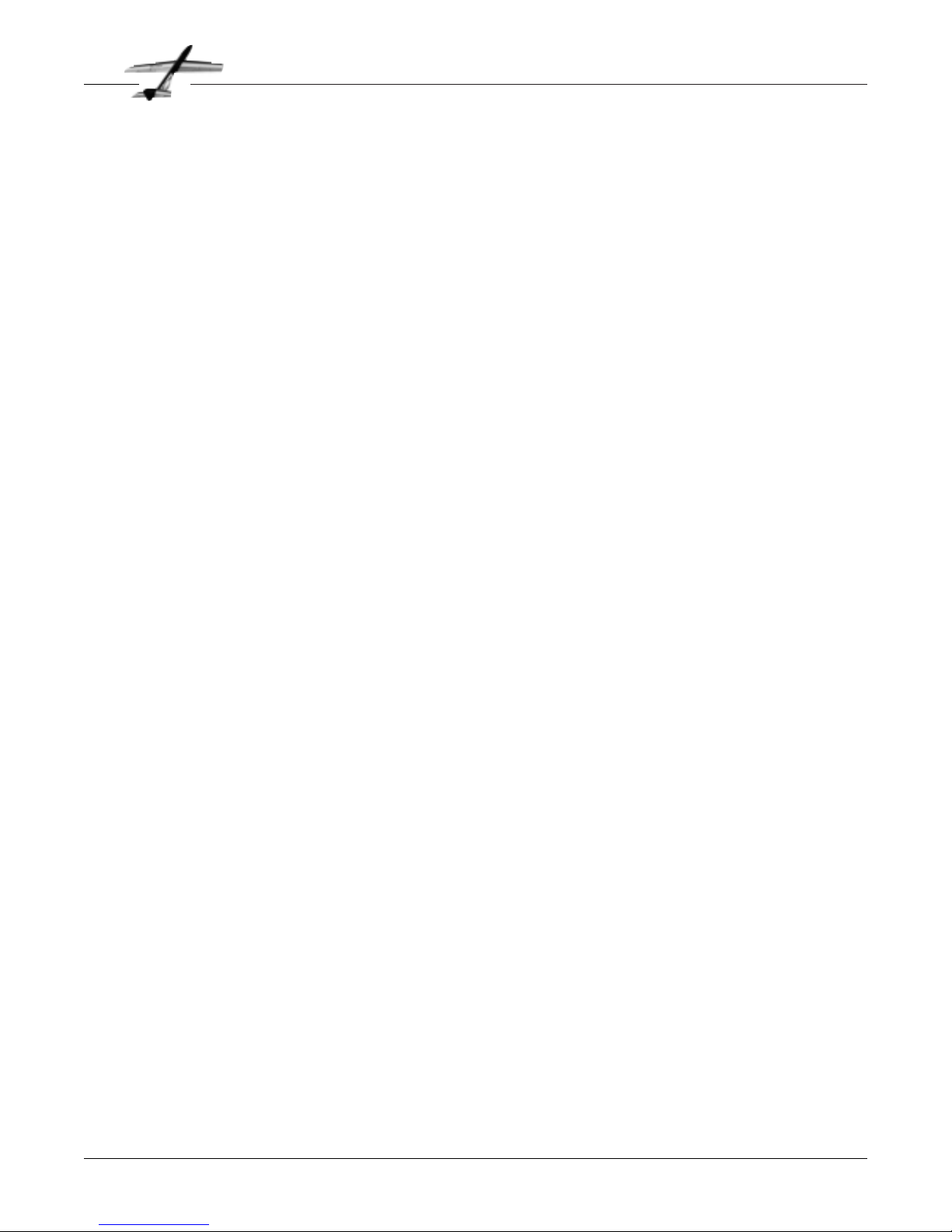
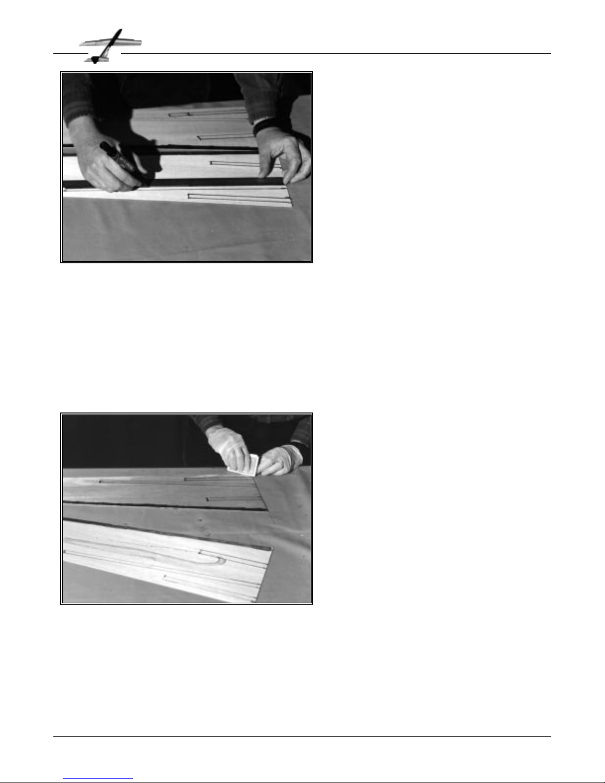
To use an aliphatic resin glue, lay the sheets
flat on the bench and apply a strip of masking tape along the length of the seam. Make
sure that there is no gap between the sheets.
When you have all of the sheets taped together, turn them
over and apply glue in the seams as shown. Lay the sheets flat
on the bench and wipe off the excess glue with a damp paper
towel. A few strips of masking tape will help hold the seam
closed while the glue dries. If you have a good gap-free fit
between the skins, try thinning the glue about 20% with water
and applying it with a small paint brush. This will make it easier to sand.
B
EGIN construction with the wing. We pre-
fer to build both wings at the same time,
however, you can build them individually if
you wish.
Locate the 10 pieces of
1
⁄16" x 3" x 24" balsa
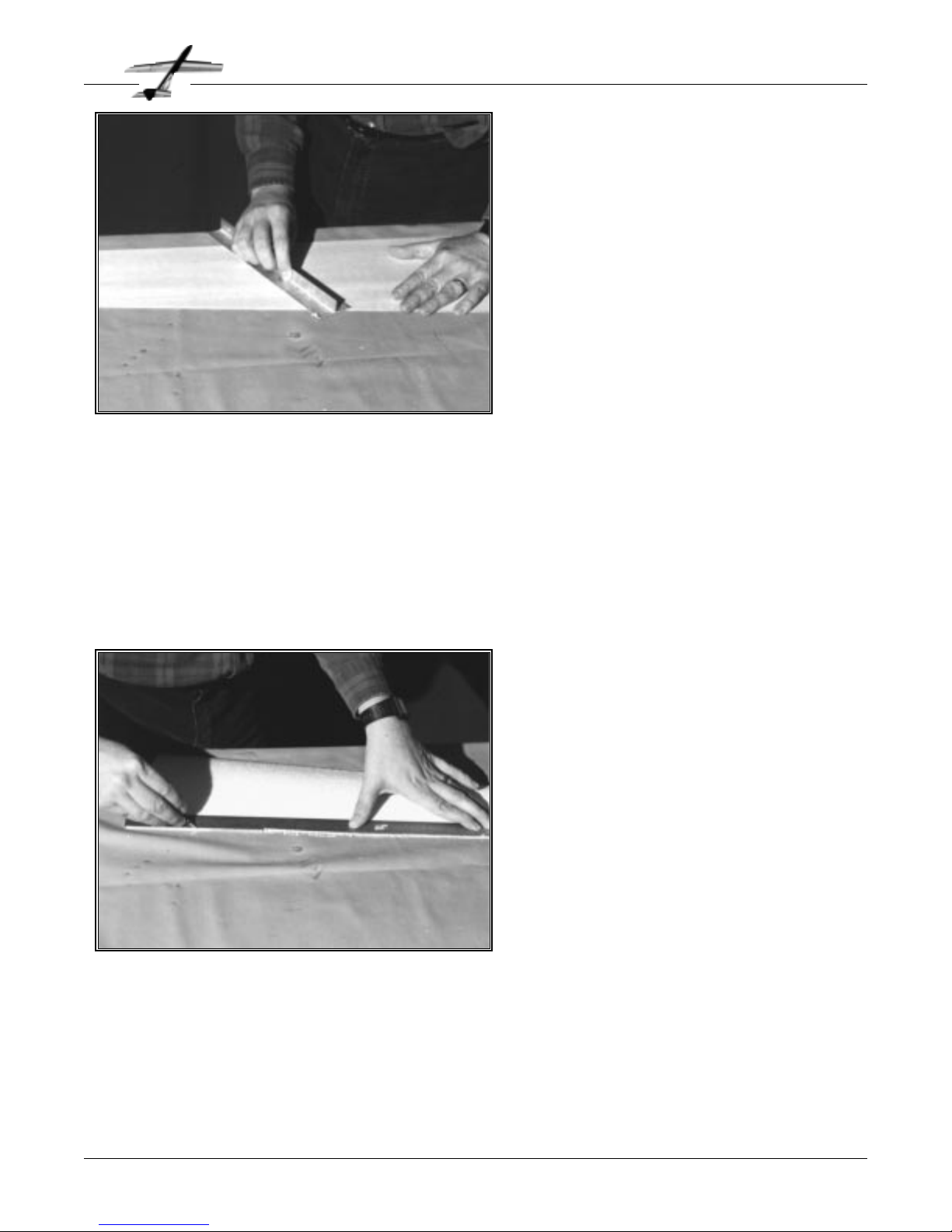
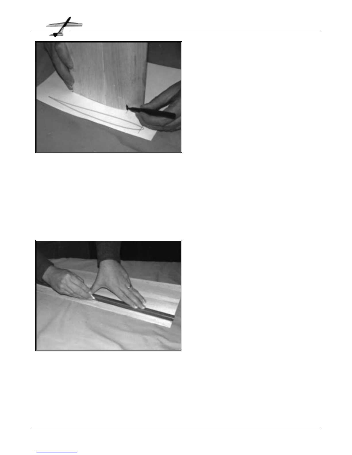
for the wing skins. Trim the edges using a
straightedge and a sharp knife blade. Make
sure that you hold the knife so the cut edges
are vertical. We find it best to make several
light cuts. Also, be careful how you hold the
straightedge so you don’t trim your fingers!
The skin splicing layout is shown on the
plans. Note that you need to splice together
two sets of 5 sheets each. Check the sheets
to verify that they fit together with no gaps. If
there is a minor problem with the fit, clean it up with a sanding block. The other option is to re-trim that edge.
Select the stiffest C-grain sheets for use on the trailing edges
of the wing. Use the more flexible A-grain wood for the leading
edges.
Trim edges of skins
Don't trim your fingers
Check that the sheets fit
Phoenix
Page 6
Wing Construction
Trim wing skins
Glue skins together
Don’t use too much glue
Glue wing skins
❏
❏
❏
❏
❏
Page 9
T
HE foam cutting process leaves some
very fine “threads” on the surface of the
core. In most cases, they can be removed by
rubbing the cores with your fingers. In some
cases, you might need to very lightly sand
the core with a fresh piece of 400 grit sandpaper. Be careful not to change the shape of
the core or gouge the wing. You do not need
to remove any of the foam itself, just the
threads. It is a good idea to support the wing
in its foam “cradle” anytime you are working
on it.
You may want to remove the threads from
the surface of the foam cradles so they don’t
accidentally end up in some glue joint later.
Next, using a sharp knife, trim off the ragged trailing edge of
the core. The trailing edge should be about
1
⁄32" thick when
you are done.
W
HEN the glue is dry, examine the wing
skins. Generally, you will find that one
side is smoother and more even than the
other. This will be the outside of the skin.
Mark the inside with a felt tip pen so you
won’t get it mixed up later. Use a good flat
sanding block (we prefer the aluminum “T”
bar as shown) and 120 grit sandpaper to
remove any excess glue. Finish sand with 320
grit. For best results, clean off all of the balsa
dust with a brush attachment on a vacuum
cleaner. We also wipe the skins with a
painters tack rag.
When the skins are smooth, trim them to
shape as shown on the plans. The dimen-
sions shown are slightly oversize to allow for trimming later.
Mark the skins “upper right”, “lower left” etc. on the inside of
the skins
Mark the inside of the skins
Sand off excess glue
Sand smooth
Clean off balsa dust
Trim to size
Phoenix
Page 7
Wing Construction
Sand wing skins
Remove “threads”
Trim trailing edge
Clean up foam cores
❏
❏
❏
❏
❏
❏
❏
Page 10
T
HERE are several types of epoxy suitable
for applying skins. To keep the weight
down, we need to use the minimum amount
of epoxy possible. This is easiest with the
low viscosity finishing resins. Most resins of
this type tend to have working times under
30 minutes. If you are familiar with vacuum
bagging, then this is not a problem. If this is
your first time, then you might want to
obtain a “laminating epoxy” with an hour or
more of working time. These are available
from most of the vacuum pump suppliers. Do
not dilute the epoxy with any type of solvent.
Mix the epoxy according to the directions.
We use about 1 ounce to do an entire set of
wings. If you are using weights instead of a vacuum bag, you
might want to use about 1
1
⁄2ounces of epoxy. If you are using
a fast setting resin, it helps to pour most of it out on the skins
as soon as it is mixed. This will extend the working time.
Now spread the epoxy on the skins using a couple of old playing cards as a squeegee. You should have some resin left for
the next step. Remember, the skin to foam glue joint does not
have to be any stronger than the foam core itself!
U
SING a felt tip pen, layout the position of
the
1
⁄2" fiberglass reinforcing tape on the
inside of the wing skins. The location of the
tape is shown on the plans. The exact position is not too critical.
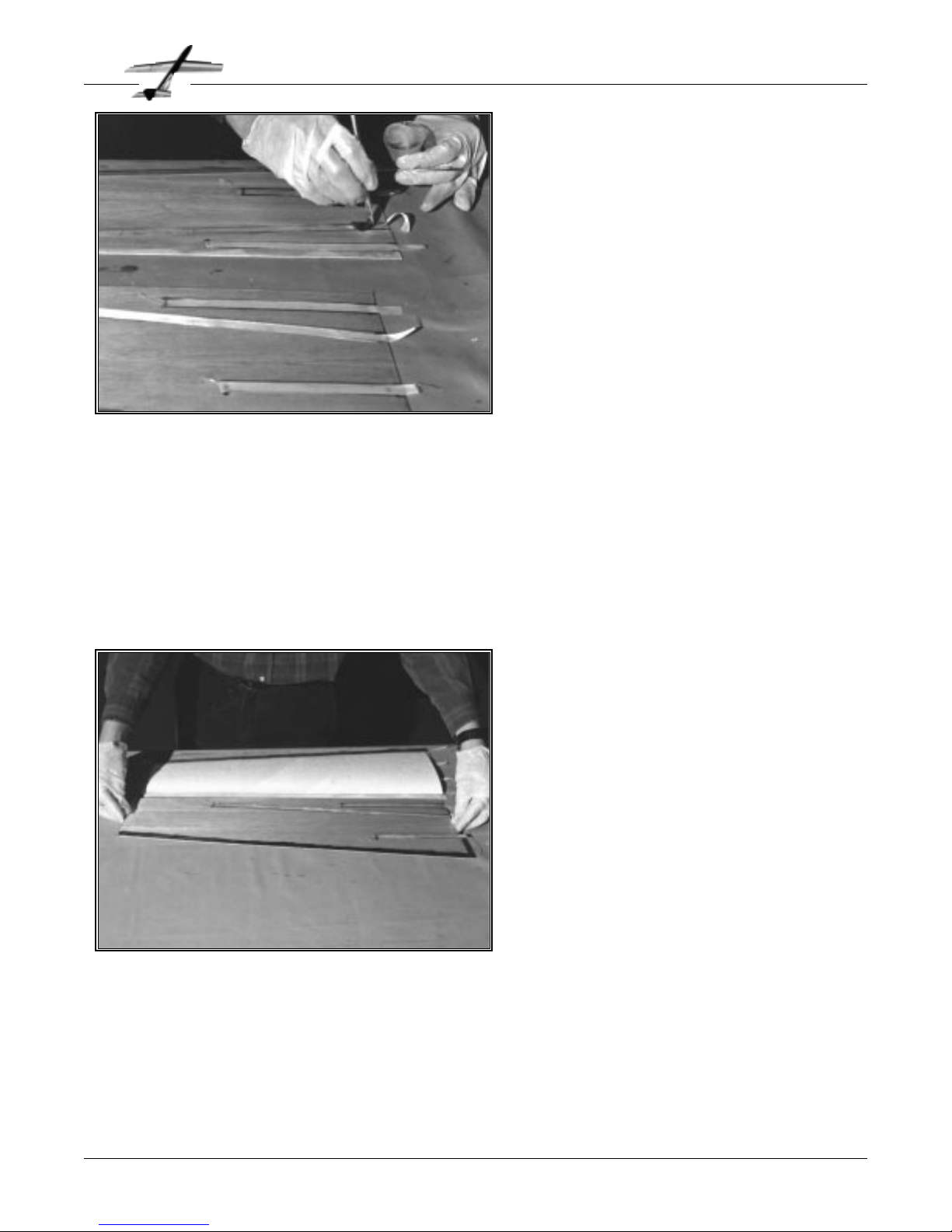
Cut the glass tape to the lengths marked on
the wing skins. Leave a half inch extra at the
wing root. Be careful when cutting the tape
since it will unravel very easily. Remember
that you only need 2 pieces of tape for the
trailing edge(left and right), while there are 4
pieces of each length (upper and lower, left
and right) for the other two lengths
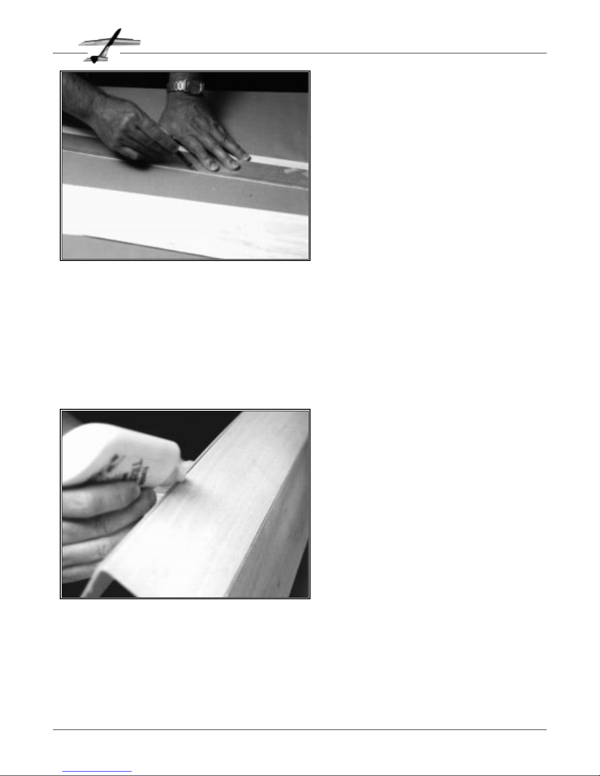
It is a good idea to color the aft
3
⁄4" of each
wing skin trailing edge with a dark color
marker as shown in the photo. This will make it easier to find
the trailing edge center line when you are sanding it later.
If you are using a vacuum bag, now is the time to get it ready.
If you are skinning both wing halves at the same time, make
the bag at least 5 feet long. Re-read the manufacturers instructions one more time. Otherwise, make sure that you have at
least 100 pounds of weights, and practice stacking them on an
area the size of the wing cradles. Once you mix the epoxy, it
will be too late…
Mark location of glass tape
Color trailing edge of skins
Cut glass tape to length
Prepare vacuum bag
Phoenix
Page 8
Wing Construction
Prepare fiberglass tape
Mix the epoxy carefully
Spread epoxy on skins
Wear gloves
Don’t use too much glue
Apply epoxy to wing skins
❏
❏
❏
❏
❏
❏
❏
❏
Page 11
P
LACE a foam core on the lower skin. The
trailing edge of the foam should be about
1
⁄16" ahead of the front edge of the trailing
edge tape as shown on the plans. Lay the
upper skin in place so that both the upper
and lower skins trailing edges are aligned.
Apply several pieces of masking tape to keep
the skins and core aligned.
P
OSITION the fiberglass tape on the skins
in the wet resin. Make sure that you apply
the trailing edge tape to the lower left skin
and to the lower right skin. The aft edge of
the trailing edge tape should be even with
the edge of the skin. Again, be careful to
avoid unravelling the ends of the tape. If you
used the right amount of epoxy on the skins,
the tape should soak up enough turn partially clear about a minute after you lay it in
place. If the tape turns completely clear, you
used too much resin and your wing will be
heavier than it needs to be. If it does not
change color at all, then you did not use
enough resin on the skins. You can go back
and add some more resin or try to squeegee some more off,
as required.
Finally, use the remaining resin and a disposable brush to
fully wet out the tape. The tape will turn clear when it is properly wetted out. Use the minimum amount of resin to make
the tape turn clear..
Now it is time to put the wings together.
Lay the tape in place
Saturate with resin
Phoenix
Page 9
Wing Construction
Apply fiberglass tape
Position core on lower skin
Lay upper skin on core
Align trailing edges
Tape together
Assemble wing
❏
❏
❏
❏
❏
❏
Page 12
I
F you are using weights, place the core and
skins in the cradle and set the upper cradle
in place. Make sure everything is aligned
properly, and use masking tape to hold the
stack together. (A good place to check it is at
the leading edge.) Carefully set weights on
top, until you have at least 50 pounds, and
preferably over 100 pounds. Remember, the
vacuum bag is equivalent to about 500
pounds per wing panel.
Be careful, since many workbenches will
bend noticeably with this kind of weight on
them, resulting in a warped wing. The best
place to do the wing assembly is on a flat
concrete floor(check it first!). If you have to
set up the wing on a workbench or wood floor, we suggest
that you get a couple of flat 2" x 10" boards at least 30" long to
set everything on. This will help keep the wing straight.
Regardless of the technique you use to hold everything
together, wait until the epoxy is fully cured before proceeding.
We prefer to wait about 50% longer than the epoxy manufacturer suggests, just to be safe. Remember, epoxy can take a
very long time to cure at low temperatures.
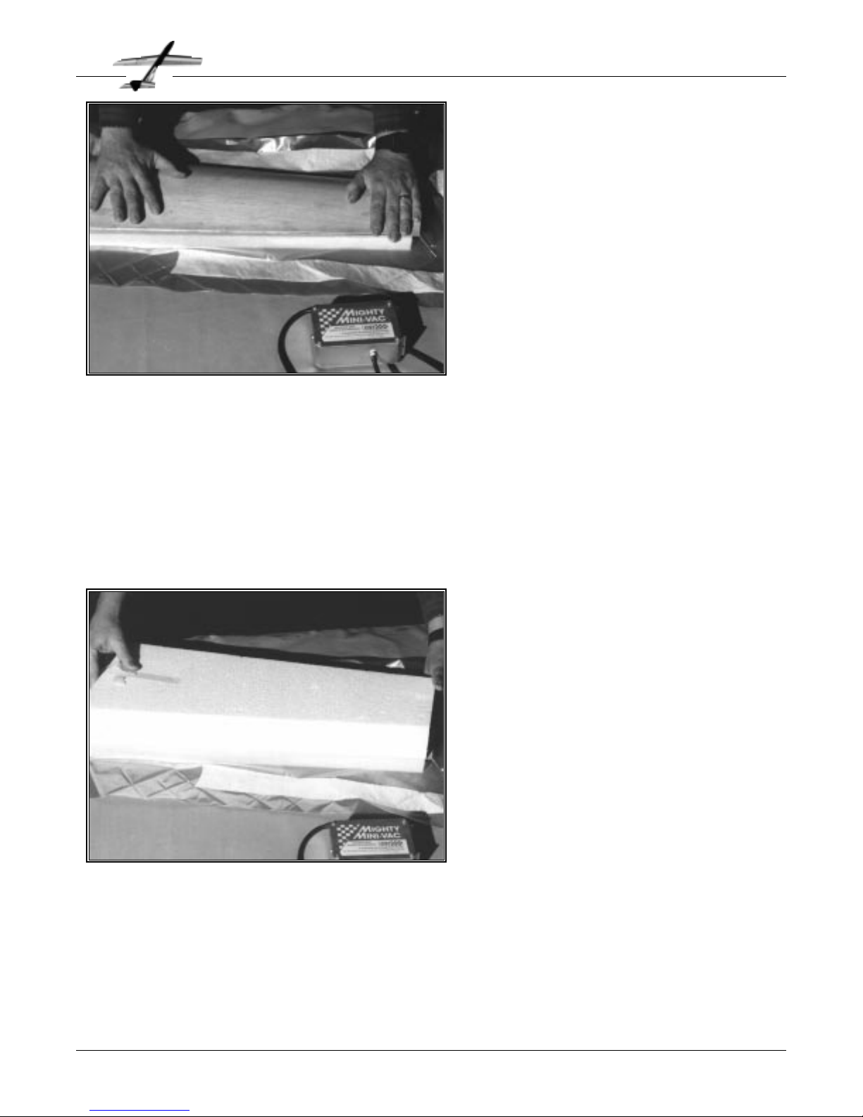
N
OW, apply pressure to the wing to hold
everything together while the epoxy
cures. If you are using a vacuum bag, insert
the wings and finish sealing the bag. Set the
entire bag assembly on the appropriate foam
cradles, and align the wings in the cradles.
Start the pump. As the air is removed, hold
the wings flat in the cradle as shown to avoid
warps.
If you have a vacuum gauge and regulator, set
the system for about 3 psi (6 inches of mercury). Pumps like the one in the photo are
preset for this value. Make sure that the wing
is still straight. If not, shut off the pump,
bleed some air into the bag, straighten it out
and try again.
If your pump does not use a “bleed valve” to control the vacu-
um, you should shut off the pump and check for air leaks.
Watch the bag carefully, if it “relaxes” noticeably within a few
minutes, you have a leak. Check all of the seams and plumbing until you fix the problem. Sometimes you can even hear
the leak. With some experience, you will be able to judge the
pressure pretty accurately by the look and feel of the bag.
Put wing in vacuum bag
Seal the bag
Pump out the air
Make sure wing is straight
Check for leaks
Phoenix
Page 10
Wing Construction
Vacuum bag the wing
Stack weights on wing
Make sure it is straight
Wait until epoxy cures
Allow wing to cure
❏
❏
❏
❏
❏
❏
❏
❏
Page 13
S
ET THE WING panel in its cradle. Using a
straightedge and a sharp knife, trim the
leading edge on the lines you marked in the
last step. Try to keep the cut vertical. Clean
up the cut with a sanding block if required.
Glue the
3
⁄16" x 3⁄8" x 24" balsa leading edge
strip in place. We prefer to use aliphatic glue
for this step. Apply the glue to the wood and
spread it into a thin layer. Hold the balsa in
place with masking tape while the glue dries.
If you want to use CA glue, make sure it is
one of the styrofoam compatible types. Do
not use epoxy, since it is very difficult to
sand cleanly.
N
OW THAT you have this nice straight,
strong piece of balsa and foam, we need
to turn it into a wing.
First, trim the balsa skins flush with the root
and tip ends of the foam cores. This does not
have to be a particularly neat job, since we
will be trimming them again later. The
approximate trim lines are shown on the
plans.
Set the wing on the appropriate wing end airfoil section drawing, and mark the location of
the leading edge trim line on both the root
and the tip of the wing. You will probably
have to move the wing around a bit to get the
best match possible with the drawing. You
want to match up the shapes over as much of the airfoil as
possible. The fit will probably not be perfect, but do the best
you can. Repeat this process until both ends of each panel are
marked. It is a good idea to check the two panels against each
other to make sure they match.
Trim balsa flush with foam
Mark LE trim line
Match wing panels
Phoenix
Page 11
Wing Construction
Mark LE trim line
Trim wing panel
Glue on leading edge
Attach leading edge
❏
❏
❏
❏
❏
Page 14
T
HE LEADING edge is probably the most
critical part of the Phoenix wing shape.
The leading edge shape was designed to give
the best balance of low drag on launch and
good glide performance. This is the place to
put in that extra bit of effort to get things
really right.
Start out by protecting the wing with masking tape, the same as you did for the trailing
edge. Use a razor plane and sanding block to
Rough out the leading edge. At this stage,
you just want get the shape close, without
taking off too much. Again, resting the wing
in its cradle will help.
N
OW SHAPE the leading and trailing edges.
This has to be done without modifying
the contour anywhere else. The best way is
to protect the remainder of the wing with
masking tape while you are working. See the
trailing edge sketches on the plans
On the trailing edge, you need to remove the
excess balsa until you get to the fiberglass
tape. Lay a piece of masking tape on the wing
with its aft edge aligned with the aft edge of
the foam core. Add additional strips of tape
adjacent to the first one until you have at
least 2" covered. Using a straight sanding
block, sand the trailing edge to the shape on
the plans. Support the wing in its cradle
while sanding.
The black marks on the inside of the skin will help you judge
the progress of the sanding. We sand the edge until it is sharp,
and then trim it back slightly to blunt it. Yes, you can cut your
finger on one of these trailing edges!
It is hard to make the trailing edge the right shape while maintaining the proper wing chord. We prefer to get the airfoil
right, and then make the chords of the wing panels match. It
is not critical if the chord does not match the plans exactly.
Protect the wing with tape
Sand the TE to shape
Phoenix
Page 12
Wing Construction
Shape trailing edge
Protect wing with tape
Start shaping the LE
Carve leading edge
❏
❏
❏
❏
Page 15

M
ARK the aileron cutout and tip trim line
as shown on the plans. Use a fine mark-
ing pen.
Trim the tip of the wing to size with a fine
razor saw. Clean up the cut with a sanding
block and glue the tip block in place using
the same technique you used for the leading
edge.
Cut out the ailerons as shown. We make the
spanwise cut with a knife and straightedge,
similar to the way you trimmed the leading
edge. You might find it helpful to remove the
razor saw blade from its stiffening spine for
making the final chordwise cuts. Clean up the
cut with a sanding block.
O
NCE THE leading edge shape is close,
start checking things with the die cut
templates. The exact locations of the templates are shown on the plans; however, they
will still give you a good idea of the proper
shape for several inches each side of the
proper location. While it probably is not possible to get the shape exact using lightweight
balsa construction, you want to get it as
close as possible. Remove the masking tape
for the final shaping, and sand very carefully
with fine sandpaper to avoid changing the
main wing airfoil.
The most important thing is to keep the
shape smooth. The lower surface is especial-
ly critical for launch performance.
If things get really messed up, it is best to cut off the entire
leading edge strip and start over.
Check LE with templates
Sand carefully
Check LE with template
Sand carefully
Repeat until finished
Phoenix
Page 13
Wing Construction
Shape airfoil
Layout cut lines
Trim wing tips
Glue on tip blocks
Cut out ailerons
Cut out ailerons and tip
❏
❏
❏
❏
❏
❏
❏
❏
❏
Page 16

C
UT 4 aileron servo mounts from the 1⁄4" x
3
⁄8" x 6" basswood strip. The lengths are
shown on the plans. Note that the aft mount
is shorter than the front mount.
Drill
1
⁄16" diameter holes in the mounts to
match your servos. The servo is attached to
the bottom of the mounts, as shown. Use the
special #2 Allen head sheet metal screws and
wrench from the hardware package to mount
the servos. Remember to reverse the eyelets
that came with your servo to allow for this
“upside-down” mounting.
Lay the servo and mounts on the bottom of
the wing, and mark the area for the cutout.
Cut out the skin with a knife. Use a knife or
Dremel tool to remove the foam. Be careful not to cut into the
upper wing skin.
Trim the top of the mounts until the servo is flush with the
lower wing surface. Epoxy the servo mounts in place. The
mounts should be glued to the upper skin and the edge of the
lower skin.
Remove the servo. The enclosed “ball end” Allen wrench
allows easy removal of the servo screws.
T
RIM the two 3⁄16" x 3⁄8" x 9" balsa strips to
fit in the aileron cutout as shown. Glue in
place. Glue one of the die cut W-1 pieces on
each end of the cutout as shown.
Cut about
1
⁄4" from the end of each aileron so
it will fit back in the opening. Trim the leading edge of the aileron to allow for the thickness of both the wing trailing edge strip and
the
3
⁄16" thick aileron leading edge strip. Glue
the aileron leading edge strip in place. The
aileron trailing edge should match up with
the wing trailing edge with both strips in
place when you are done.
Sand one end of the aileron smooth. Glue a
W-1 in place. Trim the other end to allow for
the thickness of the other W-1, plus about
1
⁄16" extra clearance
as shown on the plans. Glue the final W-1’s in place.
When the glue is dry, sand all of the framing pieces flush with
the wing skin. Remember to protect the wing surface with
masking tape while sanding.
Glue cutout framing in place
Trim ailerons to fit
Glue aileron LE in place
Glue W-1 parts in place
Sand flush with wing
Phoenix
Page 14
Wing Construction
Install aileron framing
Attach servo to mounts
Layout and cut hole
Epoxy mounts in place
Install aileron servos
❏
❏
❏
❏
❏
❏
❏
❏
Page 17

T
RIM the wing root to the sweep angle
shown on the plans. Clean up the cut, and
sand the dihedral angle. We prop each wing
tip up 1
3
⁄4" with the root at the edge of the
workbench and use the edge of the bench to
guide the sanding block. Take your time and
get the angle right. Mark the location of the
aileron cable tunnel on top of the wing as
shown.
Glue the wing halves together with 5 minute
epoxy. Wipe off any excess glue before it
cures. It is very important make the dihedral
angle as shown on the plans. An error in the
dihedral will change the vertical location of
the CG. The resulting offset between the
thrust line and the CG will cause Phoenix to loop as it leaves
the launcher. If you change the dihedral, you will have to
change the thrust line to compensate. This will take a lot of
trial and error before you get it right again!
Glass the joint top and bottom with the 6" wide cloth and
epoxy.
When the resin is cured, trim the cloth at the leading and
trailing edges.
C
UT a “tunnel” for the aileron cable. Find a
12" long piece of brass tubing of a diameter large enough to clear your servo connectors (but not more than
1
⁄2"). Sharpen one
end with a knife or file.
Very carefully, use the tubing to cut out the
foam as shown. We generally cut about an
inch or two, remove the tubing, push the
“plug”of foam out of the brass tube with a
balsa stick and then continue. You should be
able to feel the progress of the tubing with
your other hand right through the wood
skins. Do not let the tubing cut through the
skins. Try to aim the tubing at the servo
cutout. You might want to draw some refer-
ence lines to help guide the cut. Make sure the holes on each
panel line up at the root.
It might have been easier to cut the tunnel before skinning the
wings, however the pressure from the vacuum bag would
have crushed the wing!
Sharpen tube
Cut tunnel
Phoenix
Page 15
Wing Construction
Cut aileron lead tunnel
Trim the wing roots
Sand the dihedral angle
Glue the wings together
Get the dihedral right!
Glass the wing center
Join wing halves
❏
❏
❏
❏
❏
❏
❏
Page 18

C
UT the vertical and horizontal stabilizer
parts from the
3
⁄16" x 3" balsa sheets using
a sharp knife or razor blade. Use the die cut
templates as guides. Note the grain direction
on all parts, especially the S-3’s. Square up
the edges of the parts with a sanding block.
We feel that cutting these parts out using a
template is easier than cleaning up die cut
parts. ( Light balsa die cuts very poorly.)
Glue the parts together as shown on the
plans. Use either a thick CA or an aliphatic
resin glue. Both types are relatively easy to
sand when cured. Be careful when gluing the
end grain edges, since they will tend to soak
up some glue. It is best to apply the glue,
wait a few moments for it to soak in, apply some more glue
and then assemble the parts.
Sand both surfaces smooth. The leading and trailing edges
should be shaped as shown on the plans. Note that the trailing edge is about
3
⁄32" thick. This provides better control
response as well as keeping the control surfaces stronger. Do
not round off the corners on the trailing edge! Cut the hinge
slots the same as you did on the ailerons. Shape the “V” on
the rudder and elevator leading edges.
C
UT the hinge slots. We like to start the
slot with a knife, and then enlarge it with
an X-acto #26 saw blade. Sand the aileron
leading edge to the “V” shape shown on the
plans after the slots are cut. We cover the
ailerons before gluing in the hinges.
The enclosed hinges are the best we have
used. Roughen the surface with 80 grit sandpaper. Flex the hinges 180° a few times for
“break-in”. Coat the hinge with 30 minute
epoxy and force some epoxy into the hinge
slot. Insert the hinge into the slot. Wipe off
any excess glue. Pinning the hinges is not
required. We glue the hinges into the control
surface, let the glue cure and then attach the
control surface to the wing.
Trim the servo arm to the shortest length that will allow full
movement without the clevis interfering with the servo arm
hub. Cut a slot in the upper surface of the wing to clear the
linkage. Mount the aileron horn, and adjust everything for the
correct throw and centering.
In case you are wondering, the aileron horn is on top to keep
it from dragging on the ground during landing and damaging
the servo gears.
Hinge ailerons
Cut slot to clear linkage
Install control horns
Make and adjust linkage
Phoenix
Page 16
Wing and Tail Construction
Install aileron linkages
Cut out parts
Clean up edges
Glue parts together
Sand and shape
Cut hinge slots
Assemble tail surfaces
❏
❏
❏
❏
❏
❏
❏
❏
❏
Page 19

T
HE tailboom is too small in cross section
to be built with internal bulkheads, so
you have to use a square or triangle on the
outside to check the alignment as you build.
Since the parts are long and narrow, you also
have to check that everything is straight.
Remove the two F-2 parts and the F-3 bulkhead from the die cut sheets. Be careful not
to break the thin legs on the bulkhead. Use a
knife to help separate the part from the sheet
if required.
Pin one F-2 onto the board. Check it with a
straightedge, and use pins to hold it straight
during assembly. This part will be the bottom
of the tailboom. Trim back of F-2 until it is
the length shown on the plans. Glue the side assemblies in
place on top of F-2. Make sure the sides are vertical. Slip the F3 bulkhead over the front and adjust the sides for a snug fit as
shown. Do not glue the bulkhead in place.
T
HERE are 8 pieces of 3⁄16" square by 30"
balsa in the kit. Pick out the two straightest and stiffest ones and save them for use as
pushrods.
Remove the F-5 pod sides from the die cut
plywood sheet. Typically, the surface finish
on one side of the plywood is better than on
the other. Make sure to use the good side of
each part on the outside of the model. Pin
the F-5’s to the board with the good side
down. Make sure you build both a right side
and a left side. Select the softest
3
⁄16" square
stringer. Cut and glue it to the bottom edge of
each F-5 as shown on the plans. Use the nose
block to determine the location of the front
of the stringer.
Remove the F-1 tailboom sides from the die cut sheets. Pin
the two F-1’s to a building board as shown. It might be necessary to bend the parts slightly to keep the edges straight as
you pin them down. Glue the stringers in place. Note the position, trim angle and length of the extra stringers near the
front.
Clean up the edges after the glue dries.
Sort stringers
Pin sides on workbench
Make a right and a left
Check for straightness
Glue on stringers
Phoenix
Page 17
Fuselage Construction
Frame tailboom sides
Pin bottom on board
Check for straightness
Glue sides in place
Check spacing at front
Check that sides are vertical
Glue sides on tail boom
❏
❏
❏
❏
❏
❏
❏
❏
❏
❏
Page 20

M
ARK and drill the 3⁄16" hole for the wing
dowel and the larger hole for the aileron
servo leads in bulkhead F-3 as shown on the
plans. (Yes, they do not show in the photo,
but it is easier to drill the holes now!) A
“bradpoint” type wood drill (available from a
good hardware store) will cut a much cleaner
hole than a normal twist drill.
Glue F-3 on the front of the tailboom as
shown. It should be perpendicular to the
workbench.
Use the pod sides to locate and mark the
position of bulkhead F-4. Note the position of
the parts on the plans. F-4 should be centered on the boom side to side. the back of F-
4 should be flush with the back of the pod sides. It should
canted forward at the bottom to match the back edge of the
pod. Glue in place with CA. You can make small adjustments
to the angle by flexing F-4 when you glue the pod sides in
place.
T
HE other F-2 is the top of the tailboom.
Trim the front and back to the length
shown on the plans. Glue it in place. Check
the entire boom one more time to make sure
everything is straight and square before the
glue dries.
Trim top to length
Glue in place
Check for straightness
Check that boom is square
Phoenix
Page 18
Fuselage Construction
Assemble tailboom
Drill holes in F-3
Glue F-3 in place
Locate position of F-4
Glue F-4 in place
Attach bulkheads to boom
❏
❏
❏
❏
❏
❏
❏
❏
Page 21

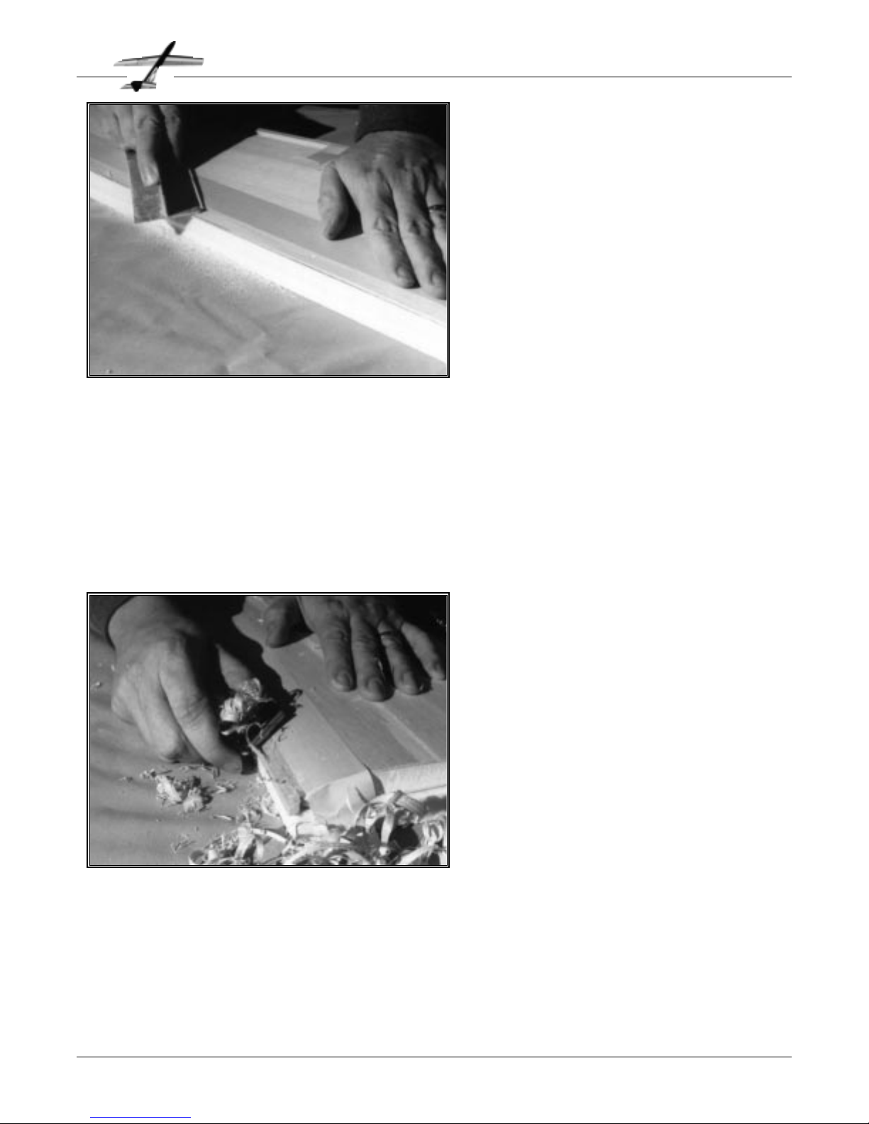
B
EVEL the top aft edge of the pod sides as
shown on the plans. Check the fit on the
boom as shown in the photo. When the sides
fit properly over the boom, glue in place. We
use either aliphatic glue or thick CA. Check
carefully to make sure the pod is straight in
relation to the boom. If you build over the
plans, check the position of the pod sides
over the drawing using a square.
This interlocking construction of the pod and
boom provides a very strong fuselage.
G
LUE the pod sides to the pre-cut hard
balsa nose block. Note that the nose
block is flush with the top and front of the
pod sides. Assemble everything together
upside down on a flat surface as shown.
Thick CA or aliphatic glue both work well.
When the glue is dry, trim and sand the bottom of the nose block flush with the bottom
of the pod sides.
Glue sides to nose block
Align nose block with sides
Trim block flush with sides
Phoenix
Page 19
Fuselage Construction
Attach pod sides to nose
Bevel aft upper edge of pod
Check fit to boom
Glue in place
Check for straightness
Glue pod to boom
❏
❏
❏
❏
❏
❏
❏
Page 22

U
SING a flat sanding block, sand the edges
of the tailboom sides and stringers flush
with the top of the pod sides. Do not sand F-
2. Carve out the bottom of the aft canopy
block to clear the pushrods.
The aft block is cut slightly oversize, and
must be trimmed to length. Place the forward
and middle canopy blocks in place as shown
on the plans. Test fit the aft block, and trim
as required.
Glue the aft canopy block in place. Make sure
to get a good bond to both the tailboom
sides and the pod sides.
W
HEN the glue is dry, determine where to
install the F-6 bulkhead. Its position is
set by the size of the rudder and elevator servos you are using. Remember to allow for the
servo mount rails. Cut the hole for the servo
leads in F-6. Glue F-6 in place.
Install the
1
⁄4" x 3⁄8" servo mounting rails. The
rails should be positioned so the servo arms
are at the height shown on the plans. Do not
drill the servo mounting holes at this time.
Sand the bottom edges of the pod smooth.
Glue F-7 and F-8 in place to the pod sides,
nose block and bulkheads. These parts are
cut slightly oversize to allow for trimming
later.
Cut servo lead hole in F-6
Glue F-6 in place
Glue servo mounts
Glue pod bottom in place
Phoenix
Page 20
Fuselage Construction
Finish pod assembly
Test fit and trim canopy
Hollow for pushrods
Glue aft block in place
Attach aft canopy block
❏
❏
❏
❏
❏
❏
❏
Page 23

M
ARK the position of the wing bolt hole
on the bottom of the wing. The hole
needs to be approximately centered on the F9 wing mounts. We prefer to make the hole
along the side of the dihedral joint instead of
on the exact center, to avoid drilling through
the epoxy.
Align the wing on the fuselage carefully.
Check the alignment by measuring from each
wingtip to the centerline at the aft end of the
tailboom. The dimensions on the right and
left sides should be identical.
Drill the hole through the wing and the F-9’s
using a number 29 drill. The hole should be
approximately perpendicular to the F-9 parts.
If you do not have a #29 drill, use a
1
⁄8" drill, and enlarge the
hole slightly with a knife or file.
G
LUE the the two F-9 aft wing mounts
together, using epoxy or thick CA glue.
When cured, glue them into the fuselage as
shown on the plans. Note that they are about
1
⁄16" above the top of the wing. Use epoxy, and
apply a fillet along the entire joint.
Place the wing in position on the fuselage
and mark the location of the wing dowel on
the leading edge. Drill a
3
⁄16" hole through the
leading edge. This is somewhat tricky, since
the drill will tend to wander off center
because of the epoxy in the dihedral joint,
but do the best you can. Trim the dowel to
length, and radius the front end with sandpaper. Chucking the dowel in an electric drill
and spinning it while sanding the radius works very well.
Insert the dowel in the wing and position the wing on the
fuselage. If necessary, use a file to enlarge the dowel hole in
the wing until the wing fits properly in its saddle.
Remove the dowel and fill the hole with an epoxy and
microballoon mixture. Insert the dowel and wipe off any
excess epoxy. Place the wing on the fuselage, align carefully
and allow the epoxy to cure.
Install F-9’s
Drill wing for dowel
Glue dowel in place
Check alignment
Phoenix
Page 21
Final Assembly
Install wing mounts
Mark hole position on wing
Align wing on fuselage
Drill hole through wing
Drill for wing mount bolt
❏
❏
❏
❏
❏
❏
❏
Page 24

T
HE motor alignment on Phoenix is very
critical. To install the motor mount accu-
rately, you need to build a jig.
Remove the J-1 and two J-2 parts from the die
cut plywood sheet and clean up the edges.
Slide the 1
1
⁄8" outside diameter liner tube
over J-1. Slide the J-2’s into place as shown.
The front end of the liner tube should be
flush with the front ends of the plywood
parts. When all the parts are properly
aligned, glue the liner tube, J-1 and the J-2’s
in place with CA.
The motor casing should be slid over the
liner tube as far as it will go. Apply masking
tape to the casing until it is a snug but not
tight fit in the 1
3
⁄16" motor mount tube. Slide the motor mount
tube over the casing until it is flush with the front of the casing.
R
EMOVE the wing. Enlarge the hole in the
F-9’s with a
11
⁄64" drill.
Installing the 6-32 blind nut is a bit tricky
since there is not a lot of room in the back of
the pod. Set the fuselage on the bench upside
down. Set the blind nut on top of the tailboom and slide it aft until it is under the
hole. Insert a 6-32 screw through the hole
and thread it a few turns into the blind nut.
Now pull the blind nut into place with the
screw. Once the nut is started into the hole,
you can tighten the screw to pull it fully into
place.
Remove the screw and apply some thin CA
around the nut so it doesn’t fall out.
Enlarge hole in F-9’s
Install blind nut
Phoenix
Page 22
Final Assembly
Install aft wing mount
Assemble jig parts
Fit casing to mount tube
Assemble motor mount jig
❏
❏
❏
❏
Page 25

T
RIM the edges of the F-10 spacers until
the motor mount tube will fit in place as
shown. The top of the motor mount tube
should just touch the bottom of the tailboom. The spacers should be within
1
⁄16" of
the motor mount tube, but not touch it. This
allows the motor alignment to be set entirely
by the jig.
Apply epoxy to the spacers and set the
motor mount tube and jig in place. Check
that the jig is sitting flat on the tailboom and
is aligned with the centerline. You can tack
glue the jig to the boom with CA if you want.
Wipe off any excess epoxy, and allow to cure.
Remove the motor casing and jig.
C
AREFULLY layout and draw a centerline
on the bottom of the tailboom.
Remove the two F-10 motor spacers from the
3
⁄32" die cut balsa sheets. Bevel the aft ends
until they will fit together as shown, and glue
in place.
A thin, trailing edge is important on the spacers where they meet. Excessive turbulence in
the airflow in this area will tend to pull the
hot motor exhaust up towards the tailboom.
Draw centerline on boom
Bevel aft end of F-10’s
Glue in place
Phoenix
Page 23
Final Assembly
Attach motor pylon
Trim F-10’s to fit tube
Glue motor mount in place
Check alignment !
Install motor mount
❏
❏
❏
❏
❏
❏
Page 26

R
EMOVE the F-11, F-12 and F-13 filler
blocks from the die cut balsa sheets. Glue
in place as shown.
We prefer to glue these parts in place with a
small amount of thick CA near the center of
each part. Next, carve and sand the pieces to
final shape. Be especially careful with the
motor mount and lower tailboom area. A
smooth, clean shape here helps to keep the
motor exhaust away from the tailboom. Since
there is no glue near the edges of the parts, it
is easy to blend them into the body shape.
Finally, flow thin CA around the edges of the
parts to firmly attach them.
Tack glue the middle canopy block in place,
then glue the forward canopy firmly in place.
Carve and sand the entire fuselage to shape as shown on the
plans. Cut the middle canopy block loose.
T
HE upper surface wing skins need to be
trimmed away to clear the motor mount
tube. Place the wing in position on the fuselage, and approximately mark the area to be
removed. Begin trimming with a knife. The
final shaping can be done with the motor casing wrapped in sandpaper as shown. Work
carefully, and keep checking the fit of the
wing to the motor tube and body. When you
are finished, the wing should again fit properly in its saddle on the fuselage.
If you trim too much, the gap can be filled
with microballoons and epoxy. Cover the
motor tube with plastic wrap to protect it,
apply the filler to the wing cutout and bolt
the wing in place. After the epoxy has cured, remove the wing
and trim the filler flush with the wing skin.
Trim top of wing
Check the fit often
Phoenix
Page 24
Final Assembly
Trim wing to clear motor
Glue filler blocks
Glue canopy blocks
Carve and shape fuselage
Remove mid canopy block
Add blocks and shape
❏
❏
❏
❏
❏
❏
Page 27

T
HIS is a good time to cover the elevator,
rudder and the trailing edges of the horizontal and vertical tails. After all of the
model is assembled, do the remainder of the
covering.
Locate the position of the elevator horn as
shown on the plans. The edge of the horn
should be as close to the vertical stabilizer
as possible. Drill the
1
⁄16" holes for the mount-
ing screws. Insert the two #4 x
3
⁄8" sheet metal
screws though the top of the elevator, and
thread them directly into the nylon control
horn. Install the elevator and rudder hinges
using the same procedure as on the aileron
hinges.
The small size of the Phoenix tail boom makes it difficult to
use a normal clevis to connect to the horns. Instead we use a
Z bend. All adjustments are made with the clevis on the servo
end of the pushrod. To remove the pushrods, simply unscrew
the control horns, and slide the entire pushrod out the back
of the tailboom. The use of the #4 screws from the top of the
elevator allows us to remove the elevator horn more easily.
F
IND the two 3⁄16" square balsa pushrods
that you set aside earlier. Bend and cut
the two pieces of
1
⁄16" Z-bend wire as shown
on the plans. There is not a lot of room in the
back of the tailboom, so make the pushrods
carefully. Drill the
1
⁄16" hole through the
pushrods. Glue the wire to the pushrods with
CA. Wrap the ends of the pushrods with
thread as shown. Saturate the thread with
glue.
Trim the rudder and elevator horns to the
length shown on the plans.
Phoenix uses wood pushrods for several reasons. First, and most important, balsa
pushrods used in a model with a balsa fuse-
lage will have essentially no change in trim with changes in
humidity or temperature. Once you get the model trimmed
out, it will stay trimmed. This is a big advantage on a model
like Phoenix. Second, if you keep the pushrods straight, they
will be very rigid, so you will have precise control at all
speeds. The Phoenix tailboom and offset vertical tail were
designed so the pushrods could be perfectly straight. Finally,
the wood pushrods are very light.
Bend and cut the wire
Glue and bind to pushrods
Trim horns to length
Phoenix
Page 25
Final Assembly
Assemble pushrods
Cover the control surfaces
Attach horn to elevator
Hinge the control surfaces
Attach elevator horn
❏
❏
❏
❏
❏
❏
Page 28

S
ET the servos in place on the mounts.
Trim a pair of servo arms so that only one
arm remains. Attach a clevis to each servo
arm. Hook up the servos to the radio, and
center the trims. Install the servo arms and
clevises.
Hold the elevator and rudder at neutral position with tape. Trim the front of the balsa
pushrods off
1
⁄4" in back of the clevises.
Remove the elevator and rudder control
horns and slide the pushrods out the back of
the boom. Remove the clevises.
Thread the clevises onto the short 2-56
threaded rods. There should be about
1
⁄8" of
threads visible inside the clevis. Attach the
threaded rod to the bottom of the pushrods with CA. Leave
1
⁄4" between the back of the clevis and the end of the balsa as
shown. Wrap the joint with thread and saturate with glue.
Reinstall the pushrods and horns.
Check the control throws, and move the clevis on the servo
arm as required. Trim off any excess servo arm. Position the
servos so the arms are as close to the center as possible, and
install the servo mount screws that came with your servos.
M
OUNT the wing to the fuselage. Check
the roll axis alignment of stabilizer and
the wing. Sand the top of the boom until the
tail is level. Glue the tail in place. Make sure
the elevator hinge line is perpendicular to
the boom centerline.
The vertical tail is mounted flush with the
side of the tail boom, not on the centerline.
This allows us to have a very strong attachment of the tail. The aft end of the F-1 tailboom side will have to be trimmed as shown
on the plans. Note the
1
⁄16" clearance between
the elevator joiner and the V-3 tailpost. You
will have to trim away some of the lower
3
⁄16"
square stringer until the outer surface of the
tailpost is flush with the side of the tailboom.
Carefully draw a centerline on the top of the horizontal tail.
Glue the vertical tail in place. You should have a good bond to
the side of the boom, the lower stringer, and the horizontal
tail. Check that the tail is vertical and parallel to the centerline. Note that the tail is not parallel to the side of the boom!
Trim the bottom of the tailpost flush with the boom.
Install the rudder horn and pushrod as shown. Make sure the
pushrods do not bind.
Align horizontal tail
Glue horizontal tail
Align vertical tail
Glue vertical tail
Attach rudder linkage
Phoenix
Page 26
Final Assembly
Attach tail surfaces
Trim pushrods to length
Attach clevises
Check control throws
Mount servos
Install servos
❏
❏
❏
❏
❏
❏
❏
❏
❏
Page 29

B
EFORE you can continue, you will need to
obtain 4 pieces of
3
⁄8" diameter aluminum
rod about 36" long. Aluminum rod is available from most good hardware stores in
either 6 or 12 foot lengths. Take a piece of the
13
⁄32" diameter by 3" long brass tube with you
to the store to make certain that the aluminum rod is a smooth slip fit in the tubing.
Next, plug one end of each of the four
13
⁄32"
diameter brass tubes. Use a knife or file to
sharpen one end of a tube by removing material from the inside edge to form a sharp
bevel. Use this as a punch to cut four discs
from
1
⁄16" scrap balsa. Glue a disc into one
end of each piece of brass tube with CA. The
discs will keep the epoxy out of the tubes. Rough up the outside of the tubes with coarse sandpaper.
Lay the launcher sides on some waxed paper or plastic wrap.
Slide the aluminum rods into the brass tubes. Glue the tubes
into the slots in the L-2 parts with epoxy. Use enough epoxy
to fill the voids between the tubing and L-1. Some epoxy will
be squeezed out of the channel. It can be cleaned off later.
Check that the rods are parallel before the glue sets. Do not
glue the aluminum rods in place.
R
EMOVE all launcher parts from the die
cut plywood sheets. Be careful when
removing the eight L-2 parts, since the area
around the slots is fragile. It is a good idea to
use a knife to remove the parts from the
sheets.
Lay the two L-1 parts on the bench. Be sure
to orient them as shown so you make both a
left side and a right side. Laminate four L-2’s
onto each L-1. This can be done with either
epoxy or a thick CA glue. Make sure that the
slots line up and are oriented as shown.
While you are at it, laminate the four L-7
parts into 2 pairs of two layers each.
If you want, sand the edges of the lamina-
tions smooth. It doesn’t make any difference in how well the
launcher works, but it does look better.
Remove parts from sheets
Laminate parts
Make a left and a right
Sand edges
Phoenix
Page 27
Launcher Assembly
Laminate launcher sides
Obtain aluminum rod
Plug ends of tubing
Glue in place
Make sure rods are parallel
Install brass tubes
❏
❏
❏
❏
❏
❏
❏
❏
Page 30

M
ARK the location of the 3⁄8" hole on one
of the sides. The exact location is not
too critical, but, you need to make sure to
miss the brass tubes,and don’t get to close to
the edge of the part.
Tape or clamp the side assemblies together.
Drill a
3
⁄8" diameter hole through both sides
for the pivot dowel. Try to keep the hole perpendicular to the sides. A“bradpoint” type
wood drill makes a much cleaner hole than a
conventional drill.
G
LUE an L-3 on top of each L-2 stack. You
might want to sand the edge of each L-3
nearest the rods before you glue them since
it will be difficult to sand later.
Fill the slots in the L-2’s with epoxy. Microballoons can be used to thicken the epoxy to
keep it from running. Coat the inside of each
L-3 with epoxy and glue in place. Clamp the
stack together until the glue cures. Do not
glue the aluminium rods in place! Also note
that the grain on the L-3 parts is parallel to L1 grain.
This is also a good time to glue the L-4 parts
in place.
Trim off the excess epoxy after everything is fully cured, and
sand the edges of the stack.
Glue on L-3’s
Fill the slots with epoxy
Glue on L-4’s
Phoenix
Page 28
Launcher Assembly
Finish sides
Layout location of hole
Clamp sides together
Drill hole
Drill for pivot dowel
❏
❏
❏
❏
❏
❏
Page 31

S
LIDE an aluminum rod into the top tube of
each side. Using the
3
⁄8" dowel as a shim,
set up the launcher as shown.
Glue the second side in place. Make sure the
rods are parallel. Tape or pin the side in
place while the glue dries.
If you want, this is the time to give the
launcher a good final sanding. Also, sand the
laminated L-7 parts smooth, and radius all
the edges except the one that will be glued to
L-6.
Radius the ends of the
3
⁄8" dowel slightly. An
easy way to do this is to chuck the dowel in
an electric drill and sand the ends while it is
spinning. Insert the dowel in the holes, make sure it is centered side to side, and glue it in place.
B
EVEL the ends of part L-5 and the two L6’s as shown on the plans. Clean up the
other edges with sandpaper.
Glue L-5 and the two L-6 ‘s onto one of the
sides as shown. Check to see that everything
is square before the glue sets.
Bevel ends of L-5 and L-6
Glue in place
Phoenix
Page 29
Launcher Assembly
Attach bulkheads
Set up as shown
Glue the side in place
Keep rods parallel
Glue the dowel in place
Attach second side
❏
❏
❏
❏
❏
❏
Page 32

A
SSEMBLE the entire launcher and your
Phoenix. Set the Phoenix in the launcher,
and center it carefully. Glue the L-7 parts in
place on top of the launcher as shown on the
plans. Allow about a
1
⁄16" space between the
L-7’s and the tailboom. Make sure the radius
on the edges of the L-7’s is smooth so they
do not scratch the finish on the model. These
parts help guide Phoenix when launching in
gusty weather.
Remove the launcher from the Mantis base.
Give the entire launcher a good coat of finishing resin to seal the wood. If you want, you
can apply extra resin, sand and paint. Just
remember, you are building a rocket launch-
er, and it will get very dirty with use, so don’t go overboard!
At least you don’t have to worry about adding too much
weight!
Finally, glue the ceramic tiles in place with epoxy. Note the
scrap
3
⁄16" balsa shim under the lower tile. You might have to
remove a paper or cloth backing from the tiles before you
glue them in place.
I
F you are going to use a Mantis™ base for
the launcher, you need to drill holes for the
elevation screw. First, note the location of
the holes on the plans. Install the launcher
adapter into the Mantis launcher by flexing
the side supports apart and inserting the
3
⁄8"
dowel in the molded holes. Using the holes in
the Mantis as a guide, drill the 2 sets of
3
⁄16"
holes. Unless you have an extra long drill bit,
you will have to drill the hole in one side, flip
the launcher over and then drill in from the
other side. Insert a screw or dowel through
the first holes to keep the parts aligned while
you drill the hole on the other side.
The exact location of the holes is not critical,
as long as the screw will fit and it is not too sloppy. The locations shown on the plans give launch elevations of about 45°
and 60° respectively. The 60° setting is used for initial flights,
while the 45° setting is better for “zoom” style launches once
your Phoenix is trimmed out.
If you want to build your own launcher base, instead of using
the Mantis base, a set of plans is provided in Appendix E.
Insert launcher in Mantis™
Drill holes as shown
Phoenix
Page 30
Launcher Assembly
Drill elevation holes
Glue on the L-7’s
Coat with resin
Install
3
⁄16" shim
Epoxy tiles in place
Final assembly
❏
❏
❏
❏
❏
❏
Page 33

Phoenix
Page 31
Finishing
Introduction
N
OW that your Phoenix is built, it is time for
its first flight, and perhaps for your first
Rocket Glider flight! Review the following sections closely, because they outline what you
need to know to successfully fly Phoenix - from
its first flight through its aerobatic and thermal
flights. Even though you may be an experienced pilot - either with power planes or with
gliders- there are a few unique steps to follow
when flying rocket gliders and you need to be
aware of them. So read the following sections
of the manual before your first flight.
The information in this section comes not only
from the 100 plus test flights of the various
Phoenix prototypes, but from many years of
teaching pilots of all skill levels how to fly rocket gliders. Learn from their experiences.
Launch Tower and Controller
I
N addition to the model, you need a launch
tower and an electrical launch controller to
fly your rocket glider. Rocket gliders, especially
Phoenix, must be launched from a tower to
ensure a safe and controllable launch. The
tower guides the model until it has reached a
speed where the controls become effective. No
other method will do. Next, the motors are
designed to be ignited electrically, by an electrical launch controller - this provides for a
safe, controllable launch.
In this kit we have included a semi-kit for the
launch tower. A launch tower is the upper part
of the launch system. It guides the model during the first critical seconds of launch. The
launch tower must be supported by a base.
You have two options. The first is to obtain the
Flying Phoenix
T
HE main thing to remember when finishing
your Phoenix is to keep it light! All of our
prototypes have been covered with iron-on
plastic film coverings. We prepare for covering
by sanding the model with progressively finer
paper, finishing up with 400 grit. Carefully vacuum the model to remove the dust. Just before
covering an area, lightly wipe it with a painters
“Tack Rag” to remove any remaining dust.
Use a cloth cover over the iron to prevent
scratching the covering. Since all of Phoenix is
sheeted with wood, we start adhering the covering near the center of the panel and work
outwards in all directions, using care to avoid
trapping bubbles of air. Once a piece of covering is fully attached, we go around the edges
using an iron without the cloth cover. The
extra heat available from the bare iron does a
better job of sticking down the edges.
The area around the motor mount tube is
tricky to cover. Use a number of small pieces of
covering and work carefully, it can be done!
For the wings, we cover the upper surface,
install the aileron servos and linkages, then
cover the bottom surface. There is no wing
servo access hatch except for the covering
itself. If you need to remove a servo, just cut
the covering away. Be especially careful near
the wing leading edge. Any wrinkle could cause
a substantial increase in drag.
We hold the canopy/hatch block in place with
standard black electrical tape. It is simple, light
and effective. If you want to do something
fancier, go ahead, but make sure your latch is
strong enough to hold the hatch on during
launch! Use the enclosed plastic tube to run
the antenna down the tailboom.
Finally, check the CG location. The position
shown on the plans is for a complete Phoenix,
with the motor casing, but without a propellant
reload or nozzle installed. The range shown is
where our prototypes balanced with no additional weight. If you need nose weight, use a
larger battery pack. If your model is nose
heavy, consider using a lighter radio system,
and enjoy the extra performance of the lighter
model!
Page 34

Phoenix
Page 32
Flying Phoenix
AeroTech Mantis™ launcher. We like it because
it is lightweight and disassembles for easy
transport.
If you would rather build your own base for the
launch tower, we've included the plans for a
base that you can build from readily available
parts. Refer to Appendix E for the plans for this
base. Note that the launch tower that we've
included works on both types of bases. So if
you start with the base that you built yourself,
you can easily upgrade it to the Mantis base at
a later date.
An electrical launch controller
and a battery are used to actually ignite the Phoenix motor.
This combination provides a
push-button, controllable
method for the launch. The
controller is essentially a
"switch" to connect the battery to the igniter that you
insert into the rocket motor
(igniters are included with
each AeroTech rocket motor).
For safe and easy operation,
we suggest you use an
AeroTech Interlock™ launch
controller. First, it has a safety
interlock switch - to help prevent your model from being
launched accidentally. Next, it
has an audible continuity indicator - so you
know that all of the connections from the battery through the igniter are all set and ready to
go. These two features - the safety interlock
switch and the continuity indicator - should be
in your electrical launch system for Phoenix,
regardless of what you use.
AeroTech offers a starter set that includes both
the Mantis launcher and the Interlock launch
controller. This is an ideal way to get going.
Information on both are included elsewhere in
this kit.
In addition to the controller, you need a battery. The standard 12 Volt rechargeable batter-
ies used to run model airplanes starters are
ideal, but a car battery can also be used.
When you wire the final system, we suggest
that the wires from the launch controller to the
model be at least 30 feet long. This provides for
more than enough space between whomever
pushes the button and the model - for safety as
well as for an ideal spot to watch the launch!
Test Glides
I
F you have experience with test gliding other
high performance RC gliders, you might want
to consider giving your
Phoenix a hand toss before
you rocket launch it. Be careful, however, Phoenix is not
an easy model to hand
launch. It has a moderately
high wing loading, and it is
difficult to hold on to while
throwing it. Just make sure
that you launch it wings
level, with the nose pointed
slightly down and with adequate flying speed. Try to
trim the model for a smooth
fast glide. If the model is
properly balanced (CG is in
the correct place) and it is
correctly built, a test glide is
not essential. So, if you would
rather not hand toss the
model, go ahead and do the
first flight with rocket power.
Launch Trim Setting
P
hoenix requires a different trim setting for
launch than it does for glide. Just like any
other airplane, it requires a different elevator
setting to fly fast than it needs to fly slow. You
actually want to set the launch trim so that the
wing will not produce any lift at all. This trim
setting is the same as you would use for a vertical dive. It is also halfway between the settings
for steady inverted flight and normal upright
flight. While the actual trim settings will vary
from one model to the next, approximate elevator positions are shown in the drawing. This
should get you close enough for first flight.
Page 35

Phoenix
Page 33
Flying Phoenix
Since there are two distinct trim settings
required, it helps to set up your transmitter to
make finding the setting easy. If you have a
transmitter with programmable mixing, it is
easy to set up a two position trim. Some transmitters designed for competition sailplanes
have this as a standard adjustment. On a
power plane transmitter, we typically will mix a
small amount of the retract gear channel into
elevator. We set the“gear down” position to
produce no change in the normal elevator settings, while “gear up” puts in the appropriate
amount of down trim for launch. Set the glide
trim normally, while the boost trim is set either
by the retract gear throw adjustment or the mixing adjustment.
You could also use throttle or
some other channel to mix with
elevator.
If your transmitter does not have
mixing, set up the launch trim to
be full down elevator trim. Once
the model is up and gliding, you
can then pull in up trim to get the
glide speed you want. Set the
launch trim by adjusting the clevis on the pushrod. That way,
you can easily and repeatably
find the correct trim setting
before launch.
Control Throws
T
he control throws shown on the plans are
the ones that we have used. The high rate
settings will give a very responsive model,
especially at high speed during launch. We use
exponential on all controls to allow both
smooth flying and aerobatics without having to
flip rate switches.
Motor Selection
F
or your first flights, obtain several AeroTech
F13-RC reload kits. These motors were
specifically designed for test flying Phoenix.
They have enough initial thrust to get the
model off of the launcher cleanly, but the sustain thrust is low enough to keep the maximum
speed reasonable. They also produce very little smoke. This is an advantage for test flights,
since you do not have to worry about flying the
model to keep it from being hidden behind its
own smoke trail. The F13 will give you a 400 to
500 foot launch altitude.
Preflight Inspection
I
t is a good idea to give your Phoenix a thor-
ough inspection before your first flight. The
CG should be in the range shown on the plans.
Check the lateral balance and add weight to
the light wing tip if required. Check all of the
controls for direction, throw and accurate centering. Do a pull test on all of the control surfaces to make sure the hinges are properly
installed. Make sure the model is structurally
sound, and has not been damaged. It is much better to find
any problems on the ground
than it is at 100 mph in the air!
First Flight
O
nce your Phoenix is fin-
ished and the launch
equipment is ready, it is time
for your first flight. Pick a day
with winds under 10 mph. You
will need an assistant to operate the launch controller so
you will be able to dedicate
your attention to flying the
model. For first flights it is a
very good idea to stand at
least 100 downwind from the launch pad. You
should be looking at the top of the model while
it is on the launcher. Standing this far back will
give you much better visibility. If your Phoenix
is out of trim and pitches up after launch, it is
very difficult to fly the model if it goes behind
you! Also by being far away from the model, it
makes it less likely that the motor's smoke trail
will be in the way and prevent you from seeing
the model.
Set up the launcher so it points upwind. If you
are using the Mantis base, set the launch elevation at the 60° position. When we fly from a
normal RC power field, we set up near the
upwind end of the runway, on the edge closest
to the pit area. Check with the field or safety
officer in your club to select the best launch
Pre-Flight Check List
Radio On
Controls Check
Trim check
Wind
Visibility
Traffic
Continuity
Announce launch
5 Second Countdown
Page 36

area. Next, set up your launch controller and
battery. Finally, load the RMS motor and install
it in the model. Perform one last check of the
radio, and make sure the elevator trim is set to
the launch position.
Install your Phoenix in the launch tower, make
sure the controller safety interlock is in the
“safe” position, and hook up the igniter clip.
Check continuity with the launch controller.
Your assistant should verify that you are ready
to launch. Check for low flying aircraft. If there
are people in the area announce
verbally that you are launching.
We use a preflight check list to
make sure we didn't forget anything.
C
HECK the controls one more
time. Your assistant should
give a 5 second countdown, and
press the launch button.
It will take a fraction of a second
for the igniter to fire. Your
Phoenix will accelerate out of
the launcher at 5 g’s. During the
first half second, while the
thrust is high and the airspeed
is low, the flight path is mostly
determined by the launcher
angle, the motor position on the model and the
wind. If there is no wind, your Phoenix will
probably pitch up slightly. If there is some
wind, it will pitch down slightly into the wind.
At the end of the first second, Phoenix will be
at 50 feet altitude moving at 60 mph.
After the first second, any errors in the launch
elevator trim will show up as a tendency to
pitch up or down. Try to fly your model in a
straight climb at approximately a 60° climb
angle. The motor will burn for about 4 1/2 seconds, and at burnout Phoenix will be moving
about 90 mph. While this is about the speed of
a pattern plane, the fact that you are going
nearly straight up and got there in a few seconds will make it seem a lot faster! Avoid
rolling during early flights until you are comfortable with the visibility and the perspective.
It is easy for new pilots to accidentally roll the
plane and become disoriented.
A
FTER the motor burns out, Phoenix will
continue to coast vertically for a few more
seconds as it slows down. When the model
slows to glide speed, change your elevator trim
to the glide position. You might want to have a
friend remind you to change to glide trim at the
top of boost. Even after hundreds of rocket
glider flights, we occasionally wonder why the
model is gliding so fast, only to realize that it is
still set for launch trim!
Now, spend some time getting the feel of your
airplane. Adjust the trims as
required, try some turns, and a
few stalls. Get set up for landing. Phoenix has a good glide
ratio, especially at moderate
speeds. Even very experienced
sailplane pilots have overshot
their first landings with
Phoenix, so allow plenty of
room!
After you land, think about
how your model flew under
power and adjust the elevator
launch trim to compensate. If
you are using mixing to provide the trim change, make the
correction in the transmitter.
(Remember to allow for any changes you made
in the glide trim setting also, since the changes
are cumulative!) If you are using the full down
trim method, make the adjustment with the clevis at the elevator servo. It will probably take
you a few flights to get your Phoenix fully
trimmed.
Once trimmed, your Phoenix should fly nearly
hands off under power. We have done some
boosts without even touching the transmitter
sticks! Of course, you will generally have to fly
the model to compensate for gusts and turbulence.
Other Phoenix Motors
Once you have gotten familiar with your
Phoenix and it is trimmed out, you should definitely try the other RMS-RC reloads available.
The G12-RC will provide initial launch performance similar to the F13’s that you have been
Phoenix
Page 34
Flying Phoenix
Phoenix launch with F13-RC
Page 37

Phoenix
Page 35
Flying Phoenix
using. The difference is that it burns twice as
long and you will go twice as high! Launch altitude will be about 1000 feet. The distance that
you should stand back from the launcher
depends upon the power of the engine. The
bigger the motor, the higher it will go, so the
farther back we stand.
With the long burn G12, you can actually get
slightly higher launch altitudes by doing a
“zoom” launch. Set your launcher to 45° elevation. Once you leave the launcher, climb out at
an angle of 30° or so. This will
allow the model to accelerate to
a higher speed than it would in a
vertical climb. After about 3 seconds, smoothly pull up to a vertical climb. After burnout, when
Phoenix slows down do a 1/4
inside loop to inverted, followed
by a 1/2 roll to a normal upright
glide (similar to an Immelman
turn). This gives the best launch
altitude possible.
AeroTech will also be providing
“special effects” reload kits in
the near future. The White Lightning™ reload produces a white
smoke trail and a large bright
exhaust flame, as shown on the
box cover. This motor has higher average
thrust and higher launch speeds. Make sure
you are comfortable with flying your Phoenix
on the F13 and G12 before trying the White
Lightning!
The BlackJack™ reload will have a dense black
smoke trail. Its thrust characteristics are such
that the model will sit on the pad for a couple
of seconds after ignition, start accelerating
moderately slowly, and then really move out!
With both of these motors, you have to fly
Phoenix so your line of sight is not obscured
by the motor’s smoke trail.
Aerobatics
Phoenix can do any aerobatic maneuver that
can be flown by a glider. We have done loops,
rolls, Cuban eights, stall turns, 4 point rolls and
even a rolling circle! Phoenix has been carefully
designed and, if correctly built, it will handle
launch loads and all maneuvers while gliding.
So try your favorite aerobatic maneuvers during glide and have fun! We have done a 900 foot
vertical dive followed by a full up elevator
loop. We also like to do rolls during the last few
seconds of the launch. At high speed, Phoenix
has a very fast roll rate!
Thermalling
On the slightly more sedate side, Phoenix can
also be thermalled for long flights. Don’t expect
Phoenix to out float your 2
pound, 100” thermal glider,
but if flown properly, it has
very good performance. The
main thing is to keep the
speed up while thermalling. It
is quite easy to fly too slow.
Try to do a smooth flat turn of
moderate diameter. While you
can fly with ailerons only, we
get the best results by holding
rudder into the turn, with
ailerons at neutral or slightly
opposite to help hold up the
inside wing. Phoenix has a
very good high speed cruise
when it is time to find the next
thermal.
Whatever you do with your Phoenix, we hope
you have as much fun with yours as we have
had with the prototypes! (Those hundreds of
test flights took a lot of time, but somebody
had to do it!)
Please let us know what you think of your
Phoenix. We welcome all of your comments
and suggestions.
Thanks again for choosing Phoenix!
White Lightning launch
Page 38

Phoenix
Page 36
Appendix A: Safety
Model flying MUST be in accordance with this Code in
order for AMA Liability Protection to apply.
GENERAL
1) I will not fly my model aircraft in competition or in the
presence of spectators until it has been proven to be airworthy by having been previously, successfully flight
tested.
2) I will not fly my model higher than approximately 400
feet within 3 miles of an airport without notifying the airport operator. I will give right-of-way and avoid flying in
the proximity of full-scale aircraft. Where necessary, an
observer shall be utilized to supervise flying to avoid having models fly in the proximity of full-scale aircraft.
3) Where established, I will abide by the safety rules for
the flying site I use, and I will not willfully and deliberately
fly my models in a careless, reckless and/or dangerous
manner.
4) If my model weighs over 20 pounds, I will only fly it in
accordance with paragraph 5 of this section of the AMA
Safety Code.
5) At air shows or model flying demonstrations a single
straight line must be established, one side of which is for
flying, with the other side for spectators. Only those persons essential to the flight operations are to be permitted
on the flying side of the line; all others must be on the
spectator side. Flying over the spectator side of the line is
prohibited, unless beyond the control of the pilot(s). The
only exceptions which may be permitted to the single
straight line requirement, under special circumstances
involving consideration of site conditions and model size,
weight, speed and power, must be jointly approved by
the AMA President and the Executive Director. In any
case, the maximum permissible takeoff weight of models
is 55 pounds.
6) I will not fly my model unless it is identified with my
name and address or AMA number, on or in the model.
Note: this does not apply to models flown indoors.
7) I will not operate models with metal-bladed propellers
or with gaseous boosts, in which gases other than air
enter their internal combustion engine(s); nor will I operate models with extremely hazardous fuels such as those
containing tetranitromethane or hydrazine.
8) I will not operate models with pyrotechnics (any
device that explodes, burns, or propels a projectile of any
kind) including, but not limited to, rockets, explosive
bombs dropped from models, smoke bombs, all explosive
gases (such as hydrogen-filled balloons), ground mounted devices launching a projectile. The only exceptions
permitted are rockets flown in accordance with the Safety
Code of the National Association of Rocketry or those
permanently attached (as per JATO use); also those items
authorized for Air Show Team use as defined by AST
Advisory Committee (document available from AMA HQ).
In any case, models using rocket motors as a primary
means of propulsion are limited to a maximum weight of
3.3 pounds and a G series motor. Note: A model aircraft is
defined as an aircraft with or without engine, not able to
carry a human being.
9) I will not fly any model using turbojet power (axial or
centrifugal flow) unless I have obtained a special waiver
for such specific flights from the AMA President and Executive Director and I will abide by any restrictions
imposed on such flights by them. (Note: this does not
apply to ducted fan models using piston engines or electric motors.)
RADIO CONTROL
1) I will have completed a successful radio equipment
ground range check before the first flight of a new or
repaired model.
2) I will not fly my model aircraft in the presence of spectators until I become a qualified flier, unless assisted by
an experienced helper.
3) I will perform my initial turn after takeoff away from
the pit or spectator areas, and I will not thereafter fly
over pit or spectator areas, unless beyond my control.
4) I will operate my model using only radio control frequencies currently allowed by the Federal Communications Commission. (Only properly licensed Amateurs are
authorized to operate equipment on Amateur Band frequencies.) Further, any transmitters that I use at a sanctioned event must have a certified R/CMA-AMA gold sticker affixed indicating that it was manufactured or modified
for operation at 20 kHz frequency separation (except 27
MHz and 53 MHz).
FREE FLIGHT
1) I will not launch my model aircraft unless at least 100
feet downwind of spectators and automobile parking.
2) I will not fly my model unless the launch area is clear of
all persons except my mechanic and officials.
3) I will employ the use of an adequate device in flight to
extinguish any fuses on the model after it has completed
its function.
CONTROL LINE
1) I will subject my complete control system (including
safety thong, where applicable) to an inspection and pull
test prior to flying.
2) I will assure that my flying area is safely clear of all utility wires or poles.
3) I will assure that my flying area is safely clear of all
non- essential participants and spectators before permitting my engine to be started.
OFFICIAL AMA SAFETY CODE
JANUARY 1, 1992
Page 39

Phoenix
Page 37
Appendix A: Safety
Rocket Glider Safety Code
In addition to the normal AMA Safety Code, a
Radio Control Rocket Glider (RG)must be flown
in accordance with the following:
1) An RG shall be propelled only by commercially-made rocket motors used in the manner
recommended by the manufacturer. A person
shall not alter the rocket motor, its parts, or its
ingredients in any way.
2) An RG shall not weigh more than 1,500
grams (53 ounces) at lift off and its rocket
motor shall produce no more than 160 newtonseconds of total impulse. An RG shall weigh no
more than the motor manufacturer’s recommended lift off weight for the motor used, or
motors recommended by the manufacturer for
the RG shall be used.
3) An RG shall be launched outdoors in an area
free of tall trees, power lines or buildings that
might be a hazard to its flight. The launch area
shall be clear of dry brush and grass.
4) An RG shall be launched from a stable
launching device that provides rigid guidance
until the RG has reached a speed adequate to
ensure a safe and predictable flight path.
When not in use on the launch field, a launching rod assembly whose free end is below eye
level shall be capped to prevent accidental eye
injury or the user shall cap the rod with his
hand when approaching it.
A launch rod assembly that is stored shall be
disassembled or capped to prevent accidental
eye injury. A launch rod assembly shall not be
stored in a vertical position with its free end at
or below eye level.
An RG launching device shall have a jet deflector to prevent the motor exhaust from hitting
the ground directly.
The area within a radius of 5 feet around the
launcher shall be cleared of brown grass, dry
weeds, or other materials that are easily ignited.
5)The system used to ignite an RG rocket
motor shall be remotely controlled and electrically operated. It shall contain a launching
switch that will return to the "off" position
when released. The system shall contain a
removable safety interlock in series with the
launch switch that will prevent electricity from
reaching the igniter until the safety interlock is
inserted in the system.
All persons shall remain at least 30 feet from an
RG being launched.
Only the electrical igniter recommended by the
rocket motor manufacturer shall be used to
ignite an RG rocket motor.
The electrical launch system and the igniter
shall be capable of igniting the RG rocket
motor within one second of actuation of the
launching switch.
6)All persons within 100 feet of the launcher
shall be made aware of the pending launch of
an RG before the person launching the RG
begins an audible five-second count-down.
If a misfire occurs in an attempt to launch an
RG, person shall not approach the launcher
until the safety interlock key has been removed
from the igniting system and one minute has
passed since the ignition attempt.
7) A person shall not launch an RG when the
wind is 20 miles an hour or more.
A person shall not launch an RG so it flies into
clouds, near aircraft in flight, or in a manner
that is hazardous to people or property.
8) When conducting flight tests with unproven
RG designs or methods, the person shall conduct the testing in complete isolation from persons not participating in the launching.
9)An RG launch device shall not be capable of
launching an RG at an angle less than 45
degrees from the horizontal. A person shall not
launch an RG at an angle less than 45 degrees
from the horizontal.
Page 40

Phoenix
Page 38
Appendix B:About Rocket Motors
R
OCKET motors are a very different animal
than a typical gas or electric model airplane engine. Here is a bit of information on the
Phoenix motors, what they are and how they
work. You do not have to know any of this to
fly Phoenix, but we thought that some of you
would be interested.
First of all, while normal model airplane
engines are rated in terms of power, either
horsepower or watts, rocket motors are rated
in what is called “total impulse”. Total impulse
is measured in “pound-seconds”. A motor with
1 pound of thrust and a burn time of 1 second
has 1 pound-second of total impulse. A motor
with .1 pound of thrust and a 10 second burn
and a motor with a 4 pound thrust and a 1/4
second burn also have one pound second of
impulse. Most small rocket motors are actually
rated in the metric system. The metric equivalent of the
pound-second
is the “Newton-second”.
There are 4.45
newtons in a
pound.
If we are flying
a spacecraft
somewhere
out in deep space, with no significant air or
gravity effects, then firing any of the three
motors will have the same effect. For example,
if our spacecraft weighs one pound, then firing
the motor will increase its speed by about 32
feet per second, about 22 miles an hour. Note
that it does not matter if we have a lot of thrust
for a short time or a low thrust for a long time.
If the total impulse is the same, it has the same
effect on speed of our spacecraft.
Things are different when we are launching
from the ground here on planet Earth where we
have both gravity and air drag to contend with.
If Phoenix weighs about 1.5 pounds, and we
use a motor with a thrust of less than 1.5
pounds, the model will never even leave the
launcher. On the other hand, if we use a really
high thrust motor, then we are likely to leave
the wings behind on the launch pad! What we
need to do is design an appropriate motor that
has enough thrust to fly the model, while still
keeping everything attached.
Fortunately, we have a bit more control of the
motor performance than just setting a thrust
level and a burn time. By specially shaping the
propellant, we can get a motor that has extra
thrust to help get the model moving and quickly get it up to a speed where the controls are
effective. We then let the thrust decrease down
to a level where we can get a nice climb at a
reasonable speed.
T
HE performance of a motor is generally
shown in what is called a thrust-time curve,
which is just a plot of thrust versus time. If we
calculate the area under the curve, in units of
thrust and time, then we have the total
impulse. This is easy if the curve is a simple
rectangle, with constant thrust. If the thrust
varies, we
either work
harder to figure the area,
or program a
computer to
do it for us.
From the
curve, we can
also find some
other interesting information, such as the peak thrust (so we
know how strong to make the wings!) and the
burn time.
Just like model airplane engines are grouped
into size categories by displacement, small
rocket motors are grouped by total impulse.
Each size category doubles the impulse of the
previous size. The Phoenix motors are
designed to fall into the “F” class (40 to 80 newton seconds) and the “G” class (80 to 160 newton-seconds). The letter designation is followed by a number indicating the average
thrust in Newtons. Thus an F5 would have
about one pound of thrust (5 Newtons) on the
average, and would burn for 8 to 16 seconds.
An F80 would average about 16 pounds of
thrust and burn for one half to one second.
T
YPICAL small rocket motors used in model
rockets are designed to allow the model to
coast for a few seconds, and then deploy a
RMS-RC 32/60-100 Motor with F13-RC reload
Page 41

Phoenix
Page 39
Appendix B:About Rocket Motors
parachute or other recovery device. The
motors contain devices called a delay charge
and ejection charge to actuate the parachute at
the preset time. The length of the time delay is
indicated by another number in the motor designation.
Thus, an F805 would have
a 5 second
delay time.
Phoenix is
radio controlled, and
we just fly it
into a glide
whenever it
slows down.
No built in
delay time is
required. The motors are designated something like “F13-RC”, where the RC stands for
“radio control”. The lack of the delay and ejection charges is the reason you cannot use a
Phoenix motor in a conventional model rocket.
If you use a conventional model rocket motor
in Phoenix, the ejection charge will damage the
model.
W
E have included typical thrust-time
curves for some of the Phoenix motors.
The F13-RC is specifically designed for a low
cost per flight. It is also the reload kit to use for
initial flights. Its total impulse of 60 newton
seconds will launch a typical Phoenix to about
500 feet in altitude, about the same as you
would get from a typical hi-start launch. (Your
mileage may vary.) It has an initial thrust of 7
to 8 pounds. This gives an initial acceleration
of about 5 g’s to get the model up to flying
speed. The
thrust then
decreases to
about 2 pounds
(sustain thrust)
to give a nice
steady climb.
T
HE G12-RC is
designed for
high performance flying
once your
Phoenix is
trimmed out,
and you have some experience flying it. It is
basically the same motor as the F13, but it has
a longer propellant charge to give a longer
burn time and more altitude. A typical Phoenix
will reach about a 1000 foot altitude on a G12.
The impulse on the G was selected to launch
Phoenix to about the highest altitude where
you can see it well enough to still fly it. Why
does the G12 have a lower thrust than the F13
even if it has more total impulse? Well, the both
the peak thrust and the sustain thrust are the
same on the two motors, but the G spends
much more time at the sustain level, so the
average thrust is lower.
F13-RC
G12-RC
8
7
6
5
4
3
2
Thrust (pounds)
1
0
0 1 2 3 4 5
Seconds
8
7
6
5
4
3
Thrust (pounds)
2
1
0
0 1 2 3 4 5 6 7 8 9 10
Seconds
Page 42

Phoenix
Page 40
Appendix C: Parts Layout
Die cut plastic leading edge templates 1 per kit
A B C D
F-8
F-6
J-1
F-7
scrap
F-3
F-5
J-2
L-7
J-2
L-7
L-6
L-6
Die cut plywood 1/8" x 8" x 24" 1 per kit
L-2 L-2
F-4
L-1
L-2
L-3
L-2
L-3
Die cut plywood 1/8" x 8" x 24" 1 per kit
F-5
L-2
F-9
L-2L-2
F-9
L-5
L-1
L-2
L-7
L-7
L-4
L-4
F-13
W-1
F-12
F-12
F-13
F-2
F-10
F-1
Die cut balsa 3/32" x 3" x 30" 2 per kit
V-1
V-3
V-4
S-3S-3
Tail surface and fuselage parts.
Cut 1 set from 3/16" x 3 " x 30" using die cut template supplied
S-4
S-5
S-1
Tail surface and fuselage parts.
Cut 1 set from 3/16" x 3 " x 30" using die cut template supplied
F-11
V-2
S-2
S-4
S-5
Page 43

Phoenix
Page 41
Appendix D: Parts List
Sheet and strip balsa
10 wing skins 1/16 x 3 x 24 in.
2 Tail sheets 3/16 x 3 x 30 in.
2 Tail boom die cut sheets 3/32 x 3 x 30 in.
2 leading edge 3/16 x .4 x 24 in.
4 aileron le/wing te framing 3/16 x .4 x 9 in.
1 elevator joiner 3/16 x 1/2 x 12 in.
8 stringers/pushrods 3/16 x 3/16 x 30 in.
Cut balsa blocks
1 nose block
2 wing tip blocks
1 fwd canopy block
1 mid canopy block
1 aft canopy block
Other wood parts
2 plywood die cut sheets 1/8 x 8 x 24 in.
1 wing mount dowel 3/16 dia. x 3 in.
1 basswood servo rail 1/4 x 3/8 x 6 in.
1 launcher dowel 3/8 dia. x 4 in.
Other
1 left wing core
1 right wing core
1 1/2” x 13 ft. fiberglass tape
1 6” x 20” fiberglass
2 die cut cardboard templates
1 die cut plastic LE template
2 ceramic tile for jet deflector
Hardware
4 small control horns
6 small snap clevis
2 1/16" dia. Z bend wire
2 2 1/2” 2-56 threaded rod
2 1” 2-56 threaded rod
4 13/32" x 3" brass tube
1 # 6 blind nut
6 2-56 screws for control horns
8 #2 Allen sheet metal screws for wing servo mounts
1 ball end Allen wrench for #2 screw
1 Plastic antenna tube
1 6-32 x 1” nylon wing bolt
2 #4 sheet metal screws for elevator horn
13 hinges
Rocket motor package
1 RMS-RC 32/60-100 Rocket motor
1 motor mount tube
1 motor liner tube
1 Rocket motor instructions
Documents
1 instruction manual
1 plans
1 registration card
Page 44

Phoenix
Page 42
Appendix E: Launcher Base
2 x 4 Launcher Base
Not to scale
Assemble all parts with
wood screws and glue
Materials:
8 feet of 2 x 4 lumber
wood screws
wood glue (TiteBond or equiv.)
Cut 2 x 4 as follows:
2 pieces 3' long
1 piece 15" long
2 pieces 4" long
Top View
Launch tower not shown
Attach Launch tower
to base with
wood screws
Front View
36" long launcher legs
2 required
4" long spacer blocks
2 required
Front
4" long spacer blocks
2 required
15" long upright
1 required
Side View
launcher legs
Page 45

Phoenix
Page 43
Appendix F: Suppliers
Epoxy and Vacuum Bagging Supplies:
Both of these companies can supply vacuum pumps and low viscosity epoxys for applying the Phoenix wing skins. They each have a low cost vacuum bagging starter set with
pump, plumbing, and vacuum bag material.
Composite Structures Technology
P.O. Box 4615
Lancaster, CA 9353
(805) 723-3783
Aerospace Composite Products
P.O. Box 16621
Irvine, CA 92714
(714) 250-1107
3/8" Aluminum Rod for Launch Tower:
We have generally been able to find the aluminum rod in either a 6' or 12' length at a
good hardware store. We have used anodized rod from the following companies:
Macklanburg-Duncan
4041 N. Santa Fe
Oklahoma City, OK
Futura Home Products
Freeport Center
Clearfield, UT 84016
(800) 824-2049
(part number HM 1203EA)
You could also try calling aluminum suppliers in your area.
Other matierials may be substitued for the aluminum rods mentioned. We have used
some .325" diameter high quality aluminum tubes that are made for tent posts. Fibreglass
rod or tubing of an appropriate diameter will also work. Music wire
(7
⁄32" or 1⁄4" diameter)
is acceptable, but you will have to be very careful to clean and oil it after every flying
session to prevent corrosion. We do not suggest using wood dowels. The wood is not as
strong or as stiff as the other options mentioned. It is also very difficult to find dowels
that are not bent.
If you use some other type of rod, modify the launcher to keep the spacing between the
rods approximately the same as is shown on the plans.
Page 46

CONSUMER AEROSPACE
1955 South Palm St.
Suite 15
Las Vegas, NV 89104
(800) 752-8018
(702) 641-2301
Made and Printed in the U.S.A.
V 1.1
 Loading...