

Phoenix R250 Owner's Manual
4201 Lien Rd. • Madison, WI 53704
Owner’s Manual — Phoenix R250 LGR Dehumidifier
Installation, Operation & Service Instructions
Read and Save These Instructions
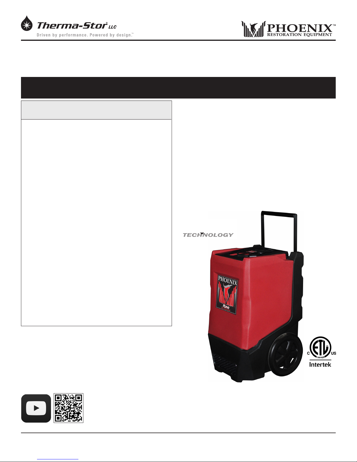
The Phoenix R250 has been redesigned from the inside out
The Phoenix R250 LGR Dehumidifier
• Coated Coils – For longer life, protection against
corrosion in the harshest environments, and protection
against the loss of the heat transfer properties of the
coil.
• Capacity - The Phoenix R250 removes 135 pints per
day at AHAM, (80°F/60%RH).
• Energy Efciency - Draws only 8.3 amps and removes
6.0 pints/kWh.
• 310 CFM - Faster drying and superior static pressure
for ducting.
• Hi-Temp Operation - up to 110°F
• Heavy-Duty Condensate Pump.
• Compact Design - 20”x20”x33.5”.
• Telescoping Handle - A heavy-duty retractable handle
for ease of transport and reduces space for storage
and stacking.
• Recessed 12” Wheels - Allows greater maneuverability
on the job site and efcient storage. Rolls over
obstacles with ease.
• Pleated Media Air Filter - A 12”x12”x1” MERV-11 lter
is standard.
• Stacking/Nesting - Reduces space for ease of stacking
and storage.
• Patented ByPass™ Technology - Increased
performance over a wide temperature range.
to be a rugged, high-performance dehumidier. Phoenix is
leading the industry by introducing epoxy coated coils. This
new feature will extend the life of the coil, provide protection in
corrosive environments, and maintain the coil’s heat transfer
ability over the life of the coil.
We kept the outstanding handle used on the R200 along with
patented ByPass™ Technology, increased airow, multiple
ducting options, and a pleated media lter. And, with some
amazing Phoenix Engineering, the R250 removes the most
water of the Phoenix rotomolds at 135 pints per day (AHAM)
while drawing only 8.3 amps of electricity, making it one of the
smallest, lightest XL category LGRs on the market.
Patented
BYPASS
www.youtube.com/user/usephoenix
Phoenix R250
Part No. 4034460
Patent 7,246,503
D570,988
8,069,681
Specifications subject to change without notice.
1
www.UsePhoenix.com • sales@UsePhoenix.comToll-Free 1-800-533-7533
TS-889
08/15
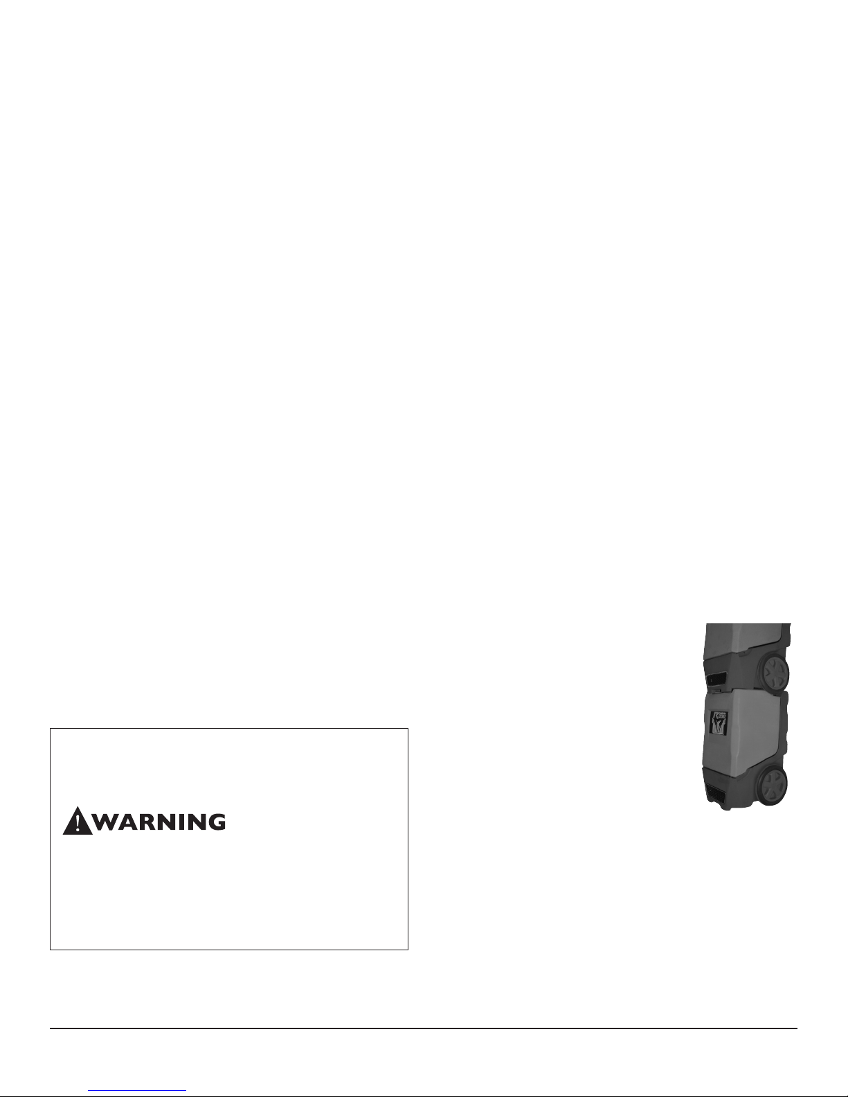
Table of Contents
Introduction ............................................................................ 1
1. Safety Certications ....................................................... 2
2. Specications .................................................................2
3. Operation ........................................................................2
3.1 Transporting ..............................................................2
3.2 Location ..................................................................... 3
3.3 Electrical Requirements ...........................................3
3.4 Condensate Removal ...............................................3
3.5 Ducting ...................................................................... 3
3.6 Defrost Cycle .............................................................3
3.7 Power Button ............................................................3
3.8 Purge Button .............................................................3
3.9 Hour Meter ................................................................ 3
3.10 Hours Button ..........................................................3
3.11 Defrost Light ........................................................... 4
3.12 Bypass Control .......................................................4
4. Maintenance ................................................................... 4
4.1 Air Filter .....................................................................4
4.2 Storage ......................................................................4
5. Service ............................................................................. 4
5.1 Technical Description ............................................... 4
5.2 Troubleshooting ........................................................ 5
5.3 Air Mover ................................................................... 6
5.4 Thermistor .................................................................6
5.5 Condensate Pump .................................................... 6
5.6 Float Safety Switch ................................................... 6
6. Options & Accessories ................................................... 7
7. Wiring Diagram ..............................................................7
8. Service Parts ................................................................... 8
9. Warranty .......................................................................... 9
Read the operation and maintenance instructions
carefully before using this unit. Proper adherence to these
instructions is essential to obtain maximum benet from
your Phoenix R250 dehumidier.
• It is designed to be used INDOORS ONLY.
• If used in a wet area, plug it into a GROUND FAULT
INTERRUPTER.
• DO NOT use the Phoenix R250 as a bench or table.
• It must always be used in the upright position.
1 Safety Certifications
The Phoenix R250 conforms to unied standard UL 60335-
2-40.
2 Specifications
Part No. 4034460
Power 8.3 amps, 120 VAC, Grounded
Water 135 pints/day @ AHAM (80°F, 60%)
Removal
Blower 310 CFM without external ducting
Refrigerant 2 lb, 0 oz. R-410A
Charge
Operating
Range
Filters:
Duct Inlet – 12” Flex-Duct
Options
Warranty Five years;
1st year 100% of Parts and Labor
2nd-5th year 100% of sealed refrigeration
system parts.
Dimensions
Width 20” 21”
Height 33.5” 35.25”
Depth 20” 21”
Weight 109 lbs 125 lbs
Patent - 7,246,503
D570,988
8,069,681
33°F to 110°F
12” x 12” x 1” Pleated Media MERV-11
Outlet – 10” Lay-Flat
Unit Shipping
3 Operation
Place dehumidier inside structure,
place condensate hose into a drain, or a
large water tight container, and turn on.
To decrease drying times, make sure all
windows and doors are closed to the outside
and seal off the affected wet areas from
unaffected areas.
Optimum performance will be observed
between the temperatures of 70°F and
95°F.
3.1 Transporting
The Phoenix R250 must always be upright when transported
by vehicle. It may be tipped on to its handle and back for
loading and moving by hand.
If the unit is transported on its side, let it sit upright at least
30 minutes before use.
Figure 1: Stacked
Phoenix R250
2
www.UsePhoenix.com • sales@UsePhoenix.comToll-Free 1-800-533-7533
3.2 Location
Note the following precautions when locating the Phoenix
R250:
• It is designed to be used INDOORS ONLY.
• If used in a wet area, plug it into a GROUND FAULT
INTERRUPTER.
• DO NOT use the Phoenix R250 as a bench or table.
• It must always be used in the upright position.
3.3 Electrical Requirements
The Phoenix R250 plugs into a common grounded outlet on
a 15 amp circuit. It draws 8.3 amps at 80°F, 60% RH. If used
in a wet area, a ground fault interrupter (GFI) is required. If
an extension cord is required, it must have a minimum of
14 gauge conductors if 25 feet long or less and 12 gauge
conductors if greater than 25 feet long.
3.4 Condensate Removal
The Phoenix R250 is equipped with an internal condensate
pump to remove the water that is condensed during
dehumidication. This pump allows the condensate to be
pumped 20 feet above the unit with the attached hose. If the
condensate must be pumped more than 20 feet above the
unit, a relay pump must be added. The condensate pump
automatically purges for 20 seconds every eight minutes. Use
the PURGE button to empty reservoir. If the condensate level
rises in the reservoir to a critical level a back-up oat switch
will activate the pump-out for up to 1 minute. If the water in
the reservoir fails to be evacuated, the safety switch will turn
off the compressor.
3.5 Ducting
A wire duct collar is supplied to allow 10” lay-at duct to be
attached to the Phoenix R250 outlet. Lay-at plastic ducting
is available (see accessories in section 6). Attach ducting to
the wire duct collar by inserting the plastic duct end through
the collar center and rolling the duct end outward to overlap
the outside of the collar. The duct and collar may then be
quickly attached to the Phoenix R250 by snapping the collar
over the four plastic exhaust tabs.
If the R250 is located in the unaffected area, the intake can
be ducted with 12” ex duct (see accessories in section 6).
Attach the ex duct to the top cover by hooking the spiral
wire under the four tabs. Tape the duct to the top cover for a
complete seal.
Figure 2: Phoenix R250 with lay-at duct.
state control and the defrost light. The control cycles the
compressor “off” and “on” by the thermistor temperature
measurement. The air mover will continue to run, causing air
to ow through the evaporator coil and melt the ice when the
compressor is off. When the air temperature and/or humidity
increases, the evaporator temperature will rise and the
thermistor will end the defrost cycle at the defrost set point.
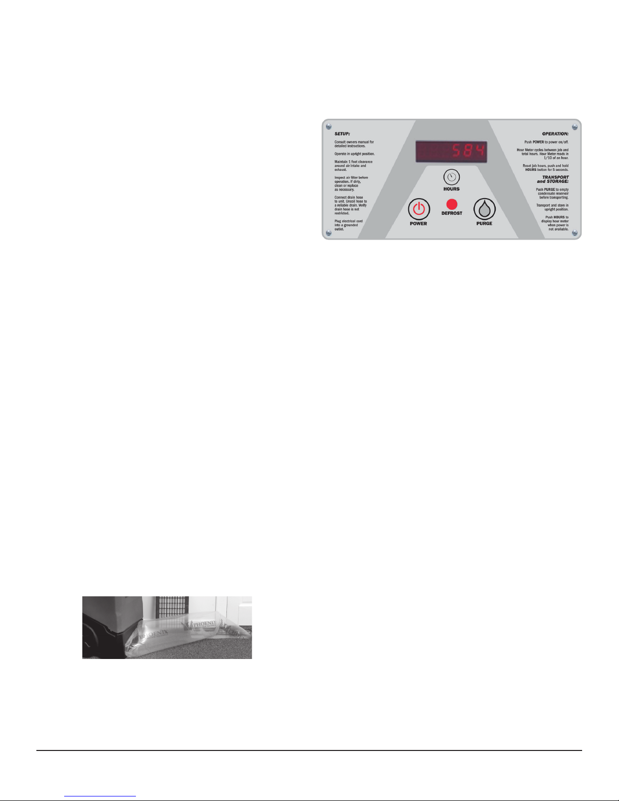
Figure 3: Phoenix R250 control board.
3.7 POWER Button
Press the POWER button to turn the dehumidier “on” or
“off”. When starting the dehumidier the display will show
the accumulated hours. Press the POWER button again to
turn the dehumidier off. The display will also power off.
3.8 PURGE Button
During normal operation the pump automatically cycles
every eight minutes. Press the PURGE button to remove
condensate manually from the reservoir. There are three
ways to manually remove water from the reservoir:
1. Press the PURGE button once and the pump will run for
20 seconds
2. Press and hold the PURGE button and the pump will run
for up to 30 seconds
3. Press the PURGE button while the dehumidier is
plugged in but powered off and the pump will run for 30
seconds.
Always manually purge the water reservoir before transport
or storage. Turn off the power and allow the plugged in
dehumidier to rest 15 minutes before the nal purge.
3.9 Hour Meter
The digital hour meter displays the amount of time the
dehumidier has been turned on to the tenth of an hour. The
hour meter continuously cycles between total machine hours
and job hours every 3 seconds. Hours are stored in memory
even when the unit is unplugged. The previous totals will be
displayed next time the unit is powered on.
3.6 Defrost Cycle
If the low side refrigerant temperature drops below the
defrost set point, due to excessive frost formation on
the evaporator coil, the thermistor activates the solid-
3.10 HOURS Button
Pressing the HOURS button displays the hour meter when the
unit is turned off but plugged into power. To reset job hours,
press and hold the HOURS button for 5 seconds when the
unit is operating.
3
www.UsePhoenix.com • sales@UsePhoenix.comToll-Free 1-800-533-7533
 Loading...