

Phoenix R175 LGR, R175 Owner's Manual
4201 Lien Rd. • Madison, WI 53704
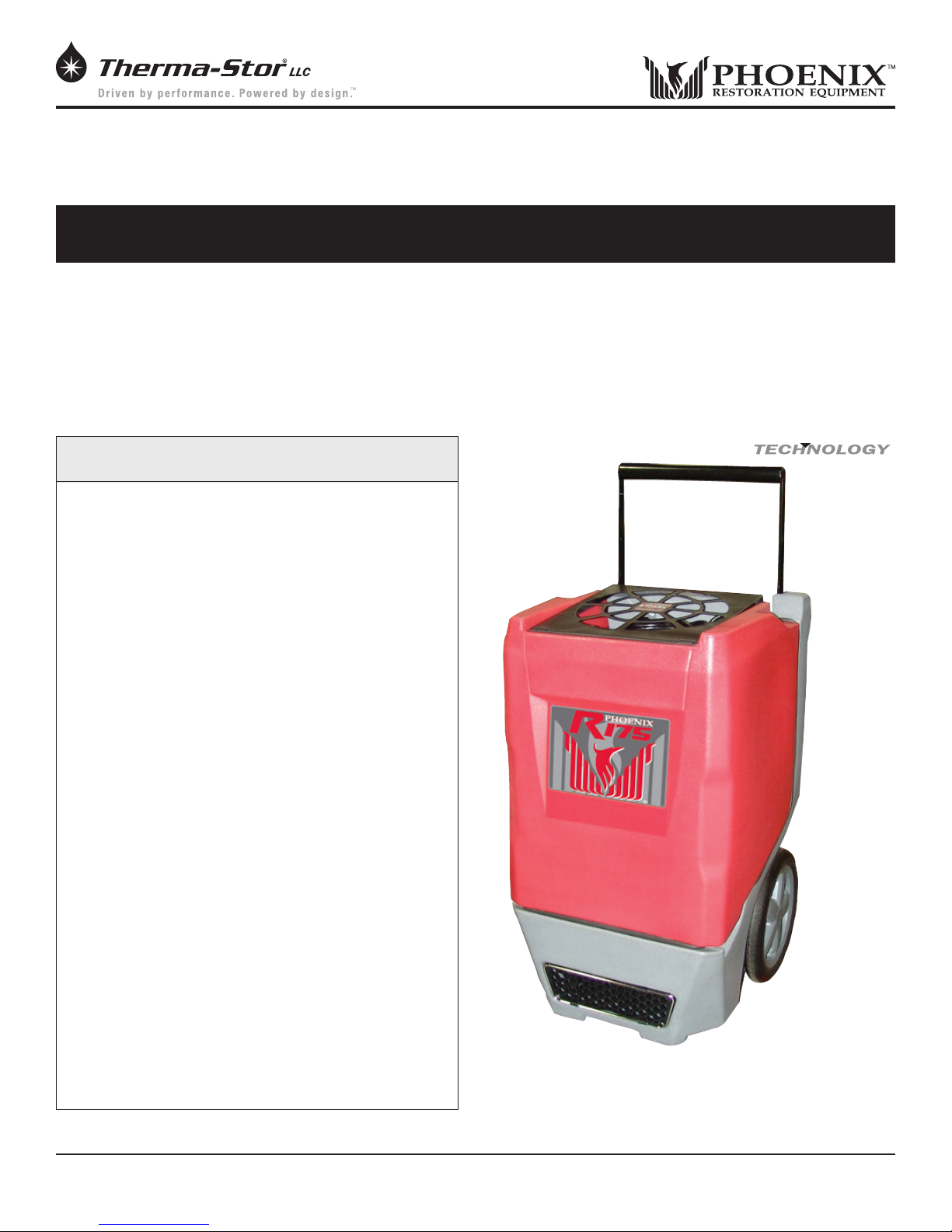
Owner’s Manual — Phoenix R175 LGR Dehumidifier
Installation, Operation & Service Instructions
Read and Save These Instructions
The Phoenix R175 is the rst roto-mold LGR (low grain
refrigerant) dehumidier manufactured by Therma-Stor,
LLC. The R175 combines Phoenix innovation, technical
expertise and proven durability. This unit will remove more
water, produce more grain depression and dry structures and
contents faster than standard refrigerant dehumidiers.
The Phoenix R175 LGR Dehumidifier
Increased Capacity - The Phoenix R175 removes over
30% more water than other dehumidiers of equal size.
Energy Efciency - Removes 92 pints at AHAM while
drawing only 6.3 amps.
Patented Bypass Technology
230 CFM - More processed air speeds drying and
provides superior static pressure for ducting.
More Grain Depression - Drier from an LGR gets your
jobs drier quicker.
Focused Airow - Patent focused outlet directs air
downward across the wet surface.
Multiple Ducting Options - 12” intake, 10” exhaust.
Plastic Housing - Rugged roto-molded housing resists
dents and scratches.
Solid State Controls - Easy to read and operate.
Protected Condensate Hose - Located under the lid.
Cannot catch or be damaged on obstructions.
Telescoping Handle - A heavy-duty retractable handle
for ease of transport and reduces space for storage and
stacking.
Recessed 12” Wheels - Allows greater maneuverability
on the job site and efcient storage. Rolls over obstacles
with ease.
Pleated Media Air Filter - A MERV-8 is standard.
Stacking/Nesting - Reduces space for ease of stacking
and storage.
Specifications subject to change without notice.
In addition to the performance benets, patented bypass
technology and tough compact size, are the multiple ducting
options, pleated media lter and energy efcient operation.
The R175 is the latest member of the Phoenix line of LGR
dehumidiers; the most effective and versatile drying devices
made.
Patented
BYPASS
Phoenix R175
Part No. 4029200
Patent 7,246,503
7,281,389
7,540,166
TS-592
03/14
™
1
www.UsePhoenix.com • sales@UsePhoenix.comToll-Free 1-800-533-7533
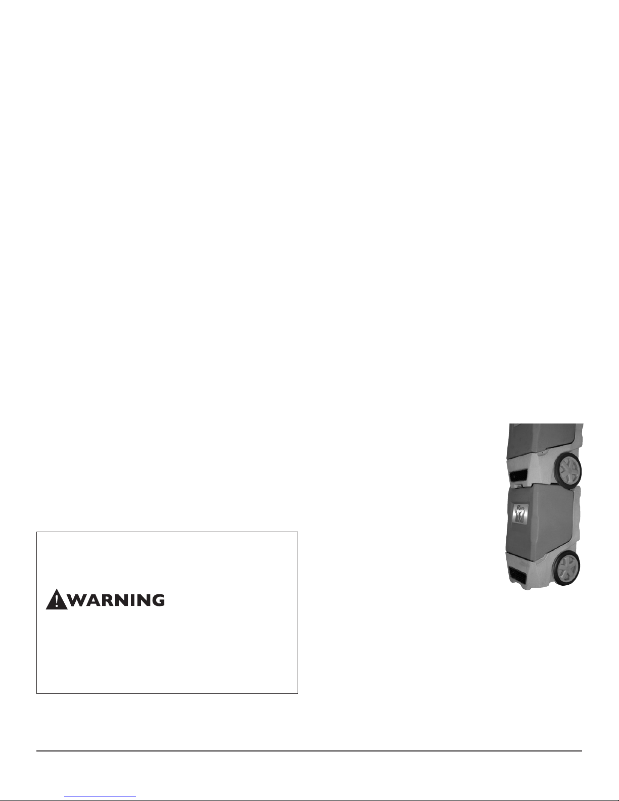
Table of Contents
Introduction ............................................................................ 1
1. Safety Certications .......................................................2
2. Specications .................................................................2
3. Operation ........................................................................2
3.1 Transporting .............................................................. 2
3.2 Electrical Requirements ...........................................3
3.3 Condensate Removal ............................................... 3
3.4 Ducting ...................................................................... 3
3.5 Defrost Cycle .............................................................3
3.6 Power Button ............................................................ 3
3.7 Purge Button .............................................................3
3.8 Hour Meter ................................................................3
3.9 Hours Button ............................................................3
3.10 Defrost Light ........................................................... 3
3.11 Bypass Control ........................................................3
4. Maintenance ................................................................... 4
4.1 Air Filter ..................................................................... 4
4.2 Storage ......................................................................4
5. Service .............................................................................4
5.1 Technical Description ............................................... 4
5.2 Troubleshooting ........................................................ 5
5.3 Air Mover ................................................................... 6
5.4 Thermistor .................................................................6
5.5 Condensate Pump ....................................................6
5.6 Float Safety Switch ...................................................6
6. Options & Accessories ................................................... 6
7. Wiring Diagram ..............................................................7
8. Service Parts ...................................................................8
9. Warranty ..........................................................................9
1 Safety Certifications
The Phoenix R175 conforms to standards ANSI/UL 474 and
CSA C22.2 No.92.
2 Specifications
Part No. 4029200
Power 6.3 amps, 110-120 VAC, Grounded
Water 92 pints/day @ AHAM (80°F, 60%)
Removal 21 gal/day maximum @ saturation
Blower 230 CFM without external ducting
210 CFM @ .15 IWG external static
Refrigerant 1 lb, 8 oz. R410a
Charge
Operating 33°F to 110°F
Range
Filter 12” x 12” x 1” Pleated Media MERV-8
Duct Intake – 12” Flex-Duct
Options Supply – 10” Lay-Flat
Warranty Five years;
1st year 100% of Parts and Labor
2nd-5th year 100% of Parts of sealed
refrigeration system.
Size 33” high x 20” wide x 20” deep
Weight 105 lbs
Patent 7,246,503
7,281,389
7,540,166
Read the operation and maintenance instructions
carefully before using this unit. Proper adherence to these
instructions is essential to obtain maximum benet from
your Phoenix R175 dehumidier.
• It is designed to be used INDOORS ONLY.
• If used in a wet area, plug it into a GROUND FAULT
INTERRUPTER.
• DO NOT use the Phoenix R175 as a bench or table.
• It must always be used in the upright position.
3 Operation
Place dehumidier inside structure, place
condensate hose into a drain, or a very
large container, and turn on. To decrease
drying times, make sure all windows and
doors are closed to the outside and seal
off the wet area from any unaffected
areas.
Figure 1: Stacked
3.1 Transporting
The Phoenix R175 features a high-impact
roto-molded housing which protects the unit airways, and
while loading into vehicles. The unit was designed to make
it easy to stack two high. The wheels of the top unit ‘nest’ in
the indentations of the bottom unit to provide stability. It is
recommended the units are properly secured for transport.
The Phoenix R175 must always be upright when transported
by vehicle. It may be tipped onto its handle and back for
loading and moving by hand.
2
www.UsePhoenix.com • sales@UsePhoenix.comToll-Free 1-800-533-7533
Phoenix R175
3.2 Electrical Requirements
The Phoenix R175 plugs into a common grounded outlet on
a 15 amp circuit. It draws 6.3 amps at 80°F, 60% RH. If used
in a wet area, a ground fault interrupter (GFI) is required. If
an extension cord is required, it must have a minimum of
14 gauge conductors if 25 feet long or less and 12 gauge
conductors if greater than 25 feet long.
3.3 Condensate Removal
The Phoenix R175 is equipped with an internal condensate
pump to remove the water that is condensed during
dehumidication. This allows the condensate to be pumped
20 feet with the attached hose. If the condensate must be
pumped more than 20 feet above the unit, a second pump
must be added to relay the condensate. The condensate
pump automatically purges for 20 seconds every eight
minutes. Use the PURGE button to manually remove
condensation.
3.4 Ducting
A wire duct collar is supplied to allow 10” lay-at duct to be
attached to the Phoenix R175 outlet. Lay-at plastic ducting
is available; see accessories table page 6. To attach ducting
to the wire duct collar, put the plastic duct end through the
collar center and roll the duct end outward so that it overlaps
the outside of the collar. The duct and collar may then be
quickly attached to the Phoenix R175 by snapping the collar
over the four exhaust tabs.
3.6 POWER Button
Press the POWER button to turn the dehumidier on or off.
When starting the dehumidier the display will show the
accumulated hours. Press the POWER button again to turn
the dehumidier off. The display will also power off.
3.7 PURGE Button
During normal operation the pump automatically cycles every
four minutes. Press the PURGE button to remove condensate
manually from the reservoir. There are several ways to
manually remove water from the reservoir:
1. Press the PURGE button once and the pump will run for
20 seconds
2. Press and hold the PURGE button and the pump will run
for up to 30 seconds
3. Press the PURGE button while the dehumidier is
powered off and the pump will run for 30 seconds.
Always manually purge the water reservoir before transport
or storage. Turn off the power and allow the plugged in
dehumidier to rest 15 minutes before the nal purge.
3.8 Hour Meter
The digital hour meter displays the amount of time the
dehumidier has been turned on to the tenth of an hour. The
hour meter continuously cycles between total machine hours
and job hours every 3 seconds. Hours are stored in memory
even when the unit is unplugged. The previous totals will be
displayed next time the unit is powered on.
3.5 Defrost Cycle
If the low side refrigerant temperature drops due to excessive
frost formation on the evaporator coil and below the temperature set point, the thermistor activates the solid-state control
and defrost light. The compressor is cycled off and on by the
thermistor temperature measurement. The air mover will
continue to run, causing air to ow through the evaporator
coil and melt the ice when the compressor is off. When the
air temperature and/or humidity increases, the evaporator
temperature will rise and the thermistor will end the defrost
cycle at the temperature set point.
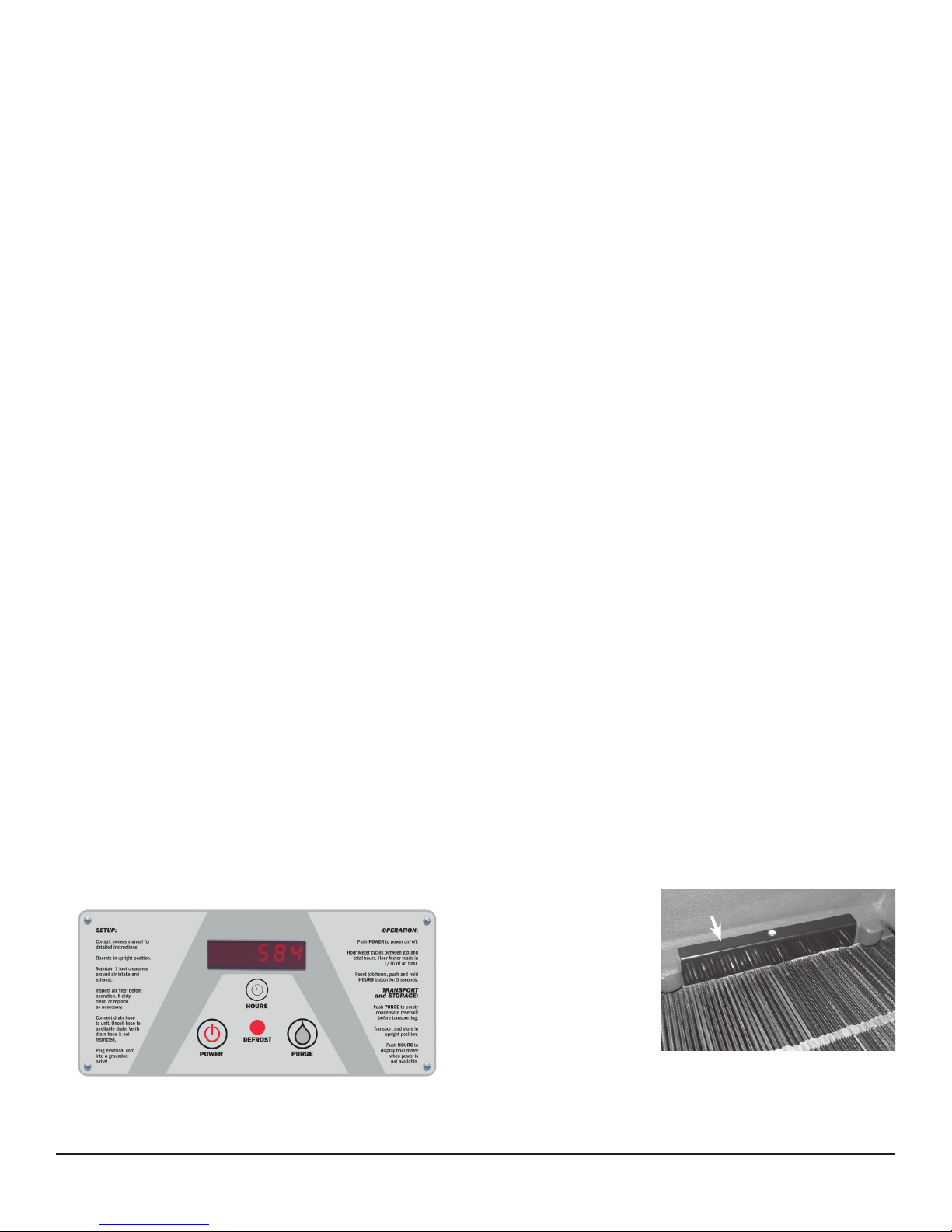
Figure 2: Phoenix R175 control board.
3.9 HOURS Button
Pressing the HOURS button displays the hour meter when the
unit is turned off but plugged into power. To reset job hours,
press and hold the HOURS button for 5 seconds when the
unit is operating.
3.10 DEFROST Light
The DEFROST light turns on when the unit is in defrost cycle
and indicates when the compressor is off.
3.11
Bypass Control
Below 90°F - When
operating the Phoenix
R175 below 90°F, the
bypass cover must close
the bypass holes, gure
3. This maximizes the
amount of air that is
dehumidied across the
evaporator. These cooler
temperatures are often found during the rst 24 hours of a
drying job.
Bypass Cover
Figure 3
3
www.UsePhoenix.com • sales@UsePhoenix.comToll-Free 1-800-533-7533
 Loading...