

Page 1
Phoenix Series
Loudspeaker
User Instructions
Safety First
The Electro-Voice PX1122M, PX1152M, PX2122, and PX2152 have threaded points that can be used for suspension.
Please consult the user instructions that are supplied with the suspension kits for proper use prior to installation.
WARNING: Suspending any object is potentially dangerous and should only be attempted by individuals who have a thorough knowledge of the techniques and regulations of rigging objects overhead. Electro-Voice strongly recommends that all speakers be suspended taking into account all current national, federal, state and local regulations. It is the responsibility of the installer to ensure that
all speakers are safely installed in accordance with all such regulations. When speakers are suspended, Electro-Voice strongly recommends that the system be inspected at least once a year. If any sign of weakness or damage is detected, remedial action should be
the loudspeaker. Any hardware used to suspend a loudspeaker that is not associated with Electro-Voice is the responsibility of others.
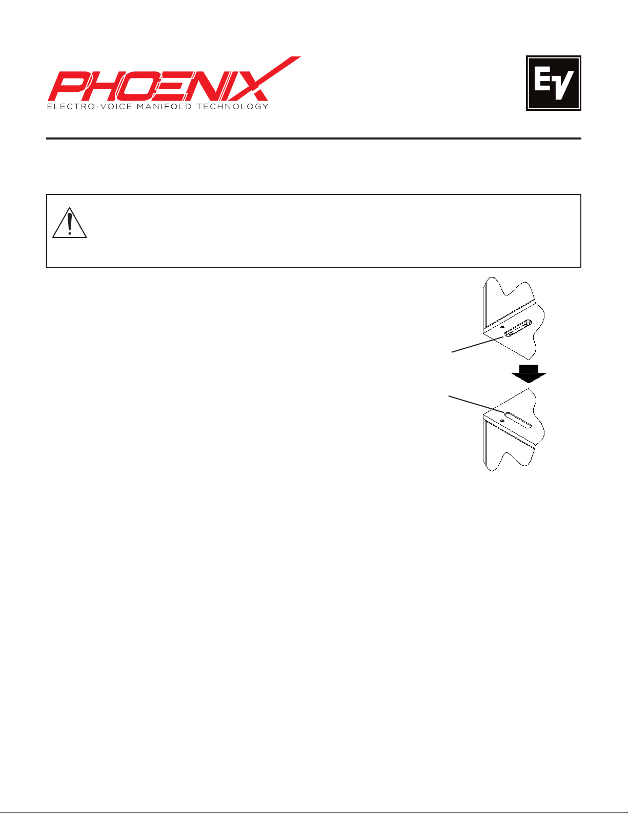
Ground Stack:
When using multiple Electro-Voice Phoenix speakers in a ground
stack configuration, the feet of each enclosure is designed to fit
into grooves of the enclosure below it. This is both for the safety
of the ground stack and serves as an alignment for properly arraying multiple loudspeakers. Always check that the feet are resting
in the grooves when using multiple speakers (Figure 1). Unless
you can safely lift the weight of the loudspeaker on to the ground
stack, have another person to help you place it. The ground stack
should be placed on a solid, level surface. When using subs on a
surface that is hard or slick, use a piece of carpet or other material
between the feet and supporting surface to prevent the subs (and
stacks) from “walking”. When using a ground stack in windy outdoor
conditions, when the surface is slippery, or when in adverse conditions, Electro-Voice recommends using a ratchet strap to secure the
speakers. For a complete list of the configurations possible with an
Electro-Voice Phoenix system, please consult the Application Guide
at www.electrovoice.com.
taken immediately. The user is responsible for making sure that the truss, and any additional hardware used, is capable of supporting
Foot on Bottom
of Second
Enclosure
Groove on Top
of First
Enclosure
Figure 1: Groundstacking Configuration
Stand Mount:
The Electro-Voice PX1122M and PX1152M include 1-3/8" stand mounts for use with tripod stands. Check the specifications of the speaker stand to be certain it is capable of supporting the weight of the speaker. Place the speaker
stand on a flat, stable surface and be sure to fully extend the legs of the stand. Do not try to make the stand “taller”
and compromise its structural integrity. Do not attempt to suspend more than one speaker on a stand designed for a
single speaker. Unless you are confident that you can safely handle lifting the weight of the speaker onto the stand, ask
another person to help you place it. Route cables and position the stand so that performers, production crew and audience members will not trip over the stand or cables and pull the speaker system over. Secure the cables with wire ties
or tape whenever possible.
Moisture:
Electro-Voice does not recommend using Phoenix loudspeakers in the rain or in high moisture environments without
protection.
Hearing Exposure:
Electro-Voice Phoenix loudspeakers are capable of producing sound pressure levels sufficient to produce permanent
hearing damage. Caution should be taken to avoid prolonged exposure to sound pressure levels exceeding 90 dB.
Processor Settings:
Processor settings for Phoenix loudspeaker configurations are available for Electro-Voice speaker processors. Please
consult the Application Guide at www.electrovoice.com for more information.
Page 2
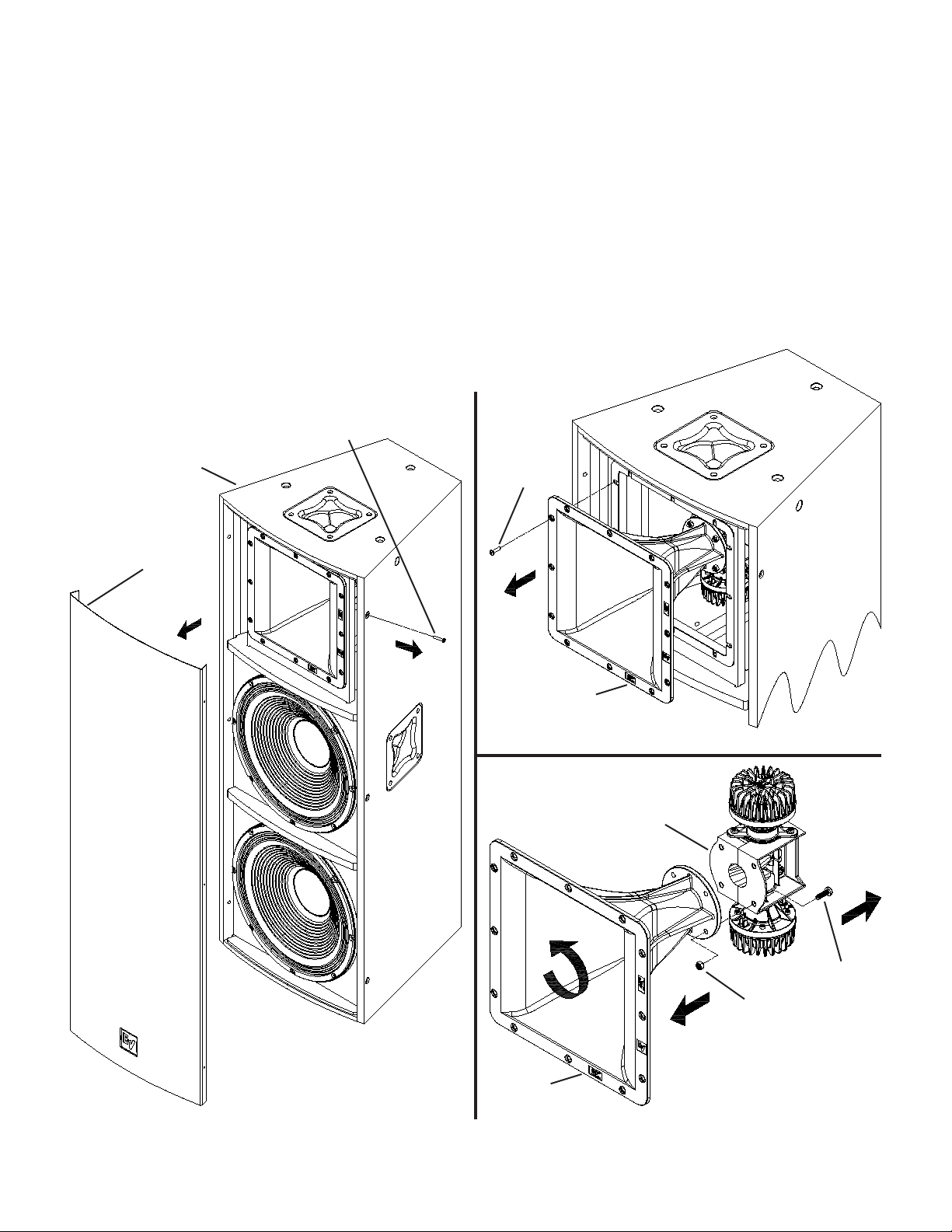
Rotating the Horn:
The PX2122 and PX2152 loudspeakers have horns that can be rotated to change the coverage pattern. The coverage
pattern angles are molded on the horn flange.
1. Remove the (6) screws that attach the grille to the enclosure (Figure 2).
2. Remove the (12) screws that attach the horn to the enclosure, and disconnect the wires that attach the ND2 to the
input panel (Figure 3). The jumper that is between both ND2’s can remain connected.
3. Remove the (4) nuts and bolts that connect the manifold to the horn. Rotate the horn 90° so the desired vertical coverage pattern is parallel to the ND2’s and manifold, then reattach the manifold using the (4) nuts and bolts (Figure 4).
4. Reconnect the wires that attach the ND2 to the input panel (reverse of Figure 3). The yellow wire corresponds to the
positive terminal, and the yellow and black wire corresponds to the negative terminal. Reattach the horn to the enclosure using the (12) screws.
5. Reattach the grille using the (6) screws (reverse of Figure 2).
Grille Screw
PX2122 or PX2152
Loudspeaker
(PX2152 Shown)
(x6)
Horn Screw
(x12)
Loudspeaker
Grille
Horn/
High-Frequency
Subassembly
Figure 3: Removing the Horn from the Enclosure
Manifold/
Compression
Driver Assembly
Manifold
Manifold
Bolt
(x4)
Nut
(x4)
Figure 2: Removing the Grille from the Enclosure
Horn
Figure 4: Detaching the Manifold Assembly from the Horn
Page 3

Adjusting the HF Level:
The PX1122M and PX1152M loudspeakers have a jumper that allows for attenuation of the HF level by 3 dB.
1. Remove the (6) screws that attach the grille to the enclosure (Figure 5).
2. Remove the (4) screws that attach the woofer to the enclosure, and disconnect the wires that attach the woofer to the
input panel (Figure 6).
3. The crossover is located on the inside of the enclosure, on the right rear wall. Move the jumper on the bottom of the
crossover to the desired location (Figure 7).
4. Reconnect the wires that attach the woofer to the input panel (reverse of Figure 6). The red wire corresponds to the
positive terminal, and the red and black wire corresponds to the negative terminal. Reattach the woofer to the enclosure
using the (4) screws.
5. Reattach the grille using the (6) screws (reverse of Figure 5).
PX1122M or PX1152M
Loudspeaker
(PX1152M Shown)
Loudspeaker
Grille
Grille Screw
(x6)
Woofer Screw
(x8)
Woofer
Figure 6: Removing the Woofer from the Enclosure
Figure 5: Removing the Grille from the Enclosure
Figure 7: Jumper Location on Crossover
Page 4

Model PX1122M PX1152M PX2122 PX2152 PX 2 18 1
Freq. Response1 (-3 dB): 70 Hz - 15 kHz 70 Hz - 15 kHz 80 Hz - 15 kHz 60 Hz - 15 kHz 45 Hz - 160 Hz
Freq. Range1 (-10 dB): 55 Hz - 19 kHz 50 Hz - 19 kHz 60 Hz - 19 kHz 50 Hz - 19 kHz 40 Hz - 18 0 Hz
Rec. Hipass Frequency: 50 Hz 45 Hz 80 Hz 40 Hz 32 Hz
Axial Sensitivity1: 98 dB (1W/1m) 100 dB (1W/1m) 102 dB (1W/1m) 99 dB (1W/1m) 105 dB (1W/1m)
Max. Calculated SPL1: 132 dB 134 dB 138 dB 136 dB 141 dB
Coverage (Horiz. x Vert.): 90° x 45° 90° x 45°
Power Handling, Passive: 600W Continuous, 2400W Peak N/A
LF Power Handling, Biamp: 500W Continuous, 2000W Peak 1000W Continuous, 4000W Peak
HF Power Handling, Biamp: 80W Continuous, 320W Peak N/A
LF Transducer(s):
HF Transducers: (2) ND2-16, 50mm (2”) Titanium Diaphragm Compression Drivers N/A
Crossover Frequency: 1.4 kHz 1.4 kHz 1.6 kHz 1.9 kHz 80 Hz - 125 Hz
Impedance, Passive: 8 Ohms Nominal N/A 4 Ohms Nominal N/A
LF Impedance, Biamp: 8 Ohms Nominal 4 Ohms Nominal
HF Impedance, Biamp: 8 Ohms Nominal N/A
Connectors: (3) Neutrik Speakon NL4’s (2) Neutrik Speakon NL4’s
Enclosure Material: 18mm Plywood, with Black EVCoat
Suspension: Rigging Point for VSA-1 Strong-Arm Accessory (8) M10 Points - (6) on Top and (2) on Bottom of Enclosure N/A
Grille: Polyester Powder Coated, 16GA Steel with Rotatable Logo
Dimensions (H x W x D):
Net Weight: 23.1 kg (50.8 lbs) 25.1 kg (55.3 lbs) 50.1 kg (110.3 lbs) 50.1 kg (111.9 lbs) 86.5 kg (190.5 lbs)
Shipping Weight: 26.2 kg (57.6 lbs) 28.2 kg (62.1 lbs) 58.9 kg (129.6 lbs) 60.6 kg (133.4 lbs) 9 4.7 kg (208.7 lbs)
Rec. Amplifier: Electro-Voice CP3000S Electro-Voice CP4000S
Accessories:
1
Half Space Measurement.
(1) DVX3121, 305mm
(12”) Woofer
546mm x 366mm x 30 5mm
(21.50” x 14.42” x 12.04”)
VSA-1 Strong-Arm Kit
TCA-1 Truss Clamp Adapter
(1) DVX3151, 381mm
(15”) Woofer
610mm x 442mm x 329mm
(24.00” x 17.42” x 12.97”)
45° x 30° or
30° x 45°
(2) DVX3121, 381mm
(15”) Woofers
1219mm x 457mm x 445mm
(48.00” x 18.00” x 17.50”)
PX-G1 Phoenix Grid
EBK-M10 Eyebolt Kit
PX-D1 Dolly Kit
60° x 45° or
45° x 60°
1200W Continuous,
4800W Peak
(2) DVX3150, 381mm
(15”) Woofers
TM
(2) DVX3180, 457mm
1219mm x 569mm x 758mm
(48.00” x 22.42” x 29.85”)
Omnidirectional
N/A
(18”) Woofers
PX-D2 Dolly Kit
Electro-Voice
12000 Portland Avenue South, Burnsville, MN 55337
Phone: 952/884-4051, Fax: 952/884-0043
www.electrovoice.com
© Bosch Communications Systems 12/2010
Part Number 38110533 Rev D
U.S.A. and Canada only. For customer orders, contact Customer Service at:
800/392-3497 Fax: 800/955-6831
Europe, Africa, and Middle East only. For customer orders, contact Customer Service at:
+ 49 9421-706 0 Fax: + 49 9421-706 265
Other Internatonal locations. For customer orders, Contact Customer Service at:
+ 1 952 884-4051 Fax: + 1 952 887-9212
For warranty repair or service information, contact the Service Repair department at:
800/685-2606
For technical assistance, contact Technical Support at: 866/78AUDIO
Specifications subject to change without notice.
 Loading...