

Page 1

TM
Instruction manual
PV-DSP-1AD.9.2 (Power Voice)
Fully automatic digital automatic mixing amplifier with a power amplifier 200 Watt and
free programmable PRESETS 1 and 2.
Programmable priority position for conference modes, input audio matrix, optional cable
remote control for remote shift of the presets.
Made in EU
3 U
PV-DSP-1AD
Version with
Audio Matrix
USB player
DeEsser
An exemplary complete equipment in the audio processing by DSP.-1A system.
Programming software MWL-Control 1.1.1
Remote LIVE control by MASTER USB interface.
Automatic system of the second generation with
DIGITAL SIGNAL DELAY FIELD
and auto-
ENGLISH
matic control of the input with BARRIER-GATE, GATE-OPEN and GAIN-CONTROL. Automatic
amplifier, DeEsser with USB MP3 player.
DIGITAL AUTOMATIC POWER MIXER with POWER AMPLIFIER 200W and DSP-1A SYSTEM
Phoenix Professional Audio GmbH
Gewerbepark Conradty 12
D-83059 KOLBERMOOR
Tel. 0049-(0)8031-30425-0
Fax. 0049-(0)8031-30425-25
www.phoenix-pa.com
info@phoenix-pa.com
shop.phoenix-pa.com
“Copyright 2015, Phoenix Professional Audio GmbH, www.phoenix-pa.com“
Phoenix logo is registered at the German Patent- and Trademark Office ( TM)
All brands are property of their respective owners.
DOC-010915
Page 2

TM
Instruction manual
SAFETY INSTRUCTIONS
Before startup of the amplifier we ask you to read the safety instructions carefully.
Installation according to the following guidelines:
1 - Always put the amplifier onto a smooth and stable lower surface.
2 - Choose a dry surrounding and do not put any liquids onto the amplifier.
3 - Avoid the closeness to heat sources.
4 - Never open the housing of the amplifier without pulling the mains plug out of the socket before.
5 - Only connect the device to 230 VAC/50Hz mains voltage.
Do not block the ventilation slots! Let above, behind and under the device a sufficient space for air circulation.
ATTENTION! Be especially careful when dealing with dangerous mains voltage. With this voltage, you can suffer
a dangerous electric shock.
This device has left the factory in safety-related correct condition. To maintain this condition and to ensure a safe operation, the
user has absolutely to observe the safety instructions and the warning notices which are contained in this instruction manual.
For damages caused by failure to observe these operating instructions, the guarantee will expire.
For the subsequent damages, the manufacturer accepts no liability.
Please check before the first startup if there is no obvious transport damage. If you discover damages to the mains line or at
the housing, please do not take the device into operation and contact your local dealer.
The construction corresponds to the protection class I. The mains plug may only be connected to a mains outlet, which voltage
and frequency exactly matches with the type label of the device. Inadequate voltages and sockets can lead to the destruction
of the device and to mortal electrical shocks.
Always insert the mains plug at last. Thereby the mains plug has to be inserted without force. Pay attention to a firm seating of
the mains plug.
Do not let the mains line come into contact with other cables. Be careful when dealing with mains lines and -connections. Never
touch these parts with clammy hands. Clammy hands can have mortal electric shocks as a consequence.
Do not change, kink, mechanically load, pull or heat mains lines and do not bring them close to heat- or cold sources. Failure to
do so may cause damages to the power line, fire or fatal electric shocks.
The cable grommet or the coupling at the device may not be tensioned. Always a sufficient cable length to the device has to be
available. Otherwise the cable can be damaged which can lead to mortal electric shocks.
Pay attention that the mains line cannot be squeezed or damaged by sharp edges. Regularly check the device and the mains
line for damages.
“Copyright 2015, Phoenix Professional Audio GmbH, www.phoenix-pa.com“
Phoenix logo is registered at the German Patent- and Trademark Office ( TM)
All brands are property of their respective owners.
1.
Page 3

TM
Instruction manual
SAFETY INSTRUCTIONS
When lines are used, it has to be ensured that the core cross-section is approved for the needed power supply of the device. All
warning indications for the mains line are also valid for possible extension lines.
Disconnect the device when it is not used and before each cleaning. To do so, touch the mains plug at the grip and never pull
on the mains line, otherwise the cable and the plug can be damaged, which can lead to mortal electric shocks. If plug or device
switch not available f.i. by installation, mains-side an all-pole shutdown has to be carried out.
When the mains plug or the device is dusty, it has to be taken out of operation, the circuit has to be interrupted all-pole and the
device has to be cleaned with a dry cloth.
Dust can reduce the isolation which can lead to mortal electric shocks. Stronger dirts in and at the device may only be removed
by a specialist.
Under no circumstances liquids of any kind may enter sockets, plug connections or any device openings or device slots.
If it is suspected, that - even minimal - liquids could have entered the device, the device has to to disconnected all-pole immediately.
This is also valid when the device has been exposed to high air humidity. Even if the device still seems to work, it has to be checked by a specialist, if possibly isolations have been affected by the liquid entry. Reduced isolations can cause mortal electric
shocks.
No foreign objects may get into the device.
This is especially valid for metal parts. Should even smallest metal parts like staples or paper clips or rougher metal swarfs get
into the device, the device has to be taken out of operation and disconnected all-pole immediately.
Malfunctions and short circuits caused by metal parts may result in fatal injuries.
The device and its supply lines have to be protected from lightning strikes.
Connect the device only when it is switched off.
Before the device is switched on, all faders and volume controls have to be set to zero or to minimum.
“Copyright 2015, Phoenix Professional Audio GmbH, www.phoenix-pa.com“
Phoenix logo is registered at the German Patent- and Trademark Office ( TM)
All brands are property of their respective owners.
2.
Page 4
TM
Instruction manual
SAFETY INSTRUCTIONS
1. Carefully read this manual.
2. Keep this manual well.
3. Consider all warnings.
4. Follow all instructions.
5. ATTENTION: to avoid fires and electric shocks, this system may not be exposed to rain and humidity. Do not use this device
close to any waters.
6. Only clean it with a dry cloth.
7. Do not cover any ventilation openings.
8. Do not put the device close to heat sources like radiators, hot air dampers, ovens or other devices (including amplifiers), which
emit warmth.
9. Do not overide the safety function of the inverse polarity or the safety plug. A plug with inverse polarity protection has two
pins, and one of them is wider than the other (only for USA/Canada). A safety plug has two pins and one ground pole. When the
included plug does not fit into your socket, the socket is obsolete and has to be replaced by an electrician.
10. Pass the mains cable in a way, that nobody can step onto it and that it cannot be jammed. This is especially valid for plugs,
sockets and the place where the cable comes out of the device.
11. Only use products and accessories specified by Phoenix Professional Audio GmbH.
12. Let maintenance operations only be carried out by qualified maintenance staff. The device has always to be maintained
when it has been damaged in any way, f.i. when the mains cable or the mains plug is damaged, if liquids have been spilled onto
the device or objects have been fallen into it, if the device has been exposed to rain or humidity, if it does not work normally or
if it has been fallen down.
EXPLANATION OF THE GRAPHIC SYMBOLS
The exclamation mark in a triangle shall advise the user of the existence of important operating- and
maintenance instructions in this manual.
The symbol consisting of a flash with an arrowhead in a triangle shall advise the user of the existence
of non-isolated, dangerous voltages within the housing, which can be strong enough to give an
electric shock.
ATTENTION: TO REDUCE THE RISK OF AN ELECTRIC SHOCK, DO NOT REMOVE THE COVER. USE QUALIFIED STAFF FOR ALL MAINTENANCE OPERATIONS.
“Copyright 2015, Phoenix Professional Audio GmbH, www.phoenix-pa.com“
Phoenix logo is registered at the German Patent- and Trademark Office ( TM)
All brands are property of their respective owners.
3.
Page 5

TM
Instruction manual
GENERAL
POWER-VOICE PV-DSP-1AD.9.2 automatic power mixer with power amplifier 200 Watt, especially developed for uses in
difficult acoustic buildings (architectural acoustic). The PV-DSP-1AD.9.2 is used in places, where most of the other devices
do not bring any positive results or where a complete „rack“ with system components would have to be built up to achieve a
reasonable acoustic result.
The 8 universal inputs are switchable by DIP-switches between MIC.- and LINE sensitivity.
Each of the 8 universal inputs has shiftable phantom power and a HPF-filter (100 Hz).
The universal inputs are equipped with shiftable automatic microphone system (DSDF),
The release of all recorded microphones is done automatically and is controlled and supervised by the processor system (DSDF).
By the input matrix (DIP switch) „MAINSUM-1“ and „MAINSUM-2“ all 8 input channels can be allocated to the „MAINSUM-1“
outputs OUTPUT 0dB (POST/PRE-MASTER), 0 dB OUTPUT and/or to the „MAINSUM-2“ output MIX-OUT.
All settings of the matrix, the DSDF system, priority or conference programming are described in the further chapters.
Besides this, the POWER VOICE DSP-1AD.9.2 has the following inputs and functions:
- Input audio matrix „MAINSUM-1“ and „MAINSUM-2“
- DeEsser with FULL, SPLIT, AIR functions
- USB MP3 player
- 8 inputs to XLR (MIC.-LINE by DIP switch)
- LINE input (LINE-9 IN) to Cinch
- 8 x input GAIN control
-15 input parametric-EQ
- 2 PRESETS
- Digital NOISE-GATE and LIMITER (software)
- RS 485 REMOTE interface for cable remote control, manual shift between the presets
- 2 100V/speaker line outputs (1 controllable zone)
- PRE-MASTER output before PEQ and MASTER (balanced to XLR)
- POST-MASTER output DSP (balanced to XLR)
- PRE-MASTER input (balanced to 3-poled jack)
- Connection for cable remote control INPUT PANEL PRESET (RJ 45)
- INFO OUT PRESET 2 (control with 2 x contact) for f.i. connection of additional speaker lines at PRESET 2
- Output RECORD for recording devices
- System software MWL-CONTROL 1.1.1
DIGITAL SIGNAL-DELAY-FIELD
system.
All these setting possibilities provide an even more precise room equalization and best adaption to the room acoustics.
Besides this, the mixing amplifiers have an additional speaker line with separate volume control and SOFT-START adjustable in
the system (standard setting 5 sec.) for better speaker protection.
The devices are suitable as desktop version as well as for 19“-installation.
“Copyright 2015, Phoenix Professional Audio GmbH, www.phoenix-pa.com“
Phoenix logo is registered at the German Patent- and Trademark Office ( TM)
All brands are property of their respective owners.
4.
Page 6
TM
Instruction manual
MAIN FEATURES
- Short circuit protection - overheating protection - open circuit protection - overload protection
- Power amplifier 200 Watt power
- RELAY CONTROL PANEL (activation at preset 2)
- 100V, 70V, 50V, 8 Ohm and 4 Ohm speaker outputs
- SOFT START to suppress switching noises
- Balanced microphone inputs
- DeEsser
- USB MP3 player
- Balanced LINE IN / LINE OUT in-/outputs
- PRESETS selector switch
- 2 WAY audio matrix
- Output RECORD for recording devices
- Phönix connectors for speaker lines
- Separate volume control for microphone, line inputs with 2-fold EQ
- Countersunk 2-element graphic EQ at the front side per input
- Feedback limiter „phase shifter“ or „adaptability automatic“
- Microphone automatic switch system with control LEDs
- Audio signal limiter and NOISE-GATE (MASTER)
- 15 x input parametric EQ with 20 Hz to 20.480 kHz @ -12dB/+12dB @ 0.05 oct - 3.00 oct
- Delay per output to 85 mtr.
- Separate speaker line with volume control, zone 1 [200 W complete amplifier power]
- Control software MWL-CONTROL via USB interface.
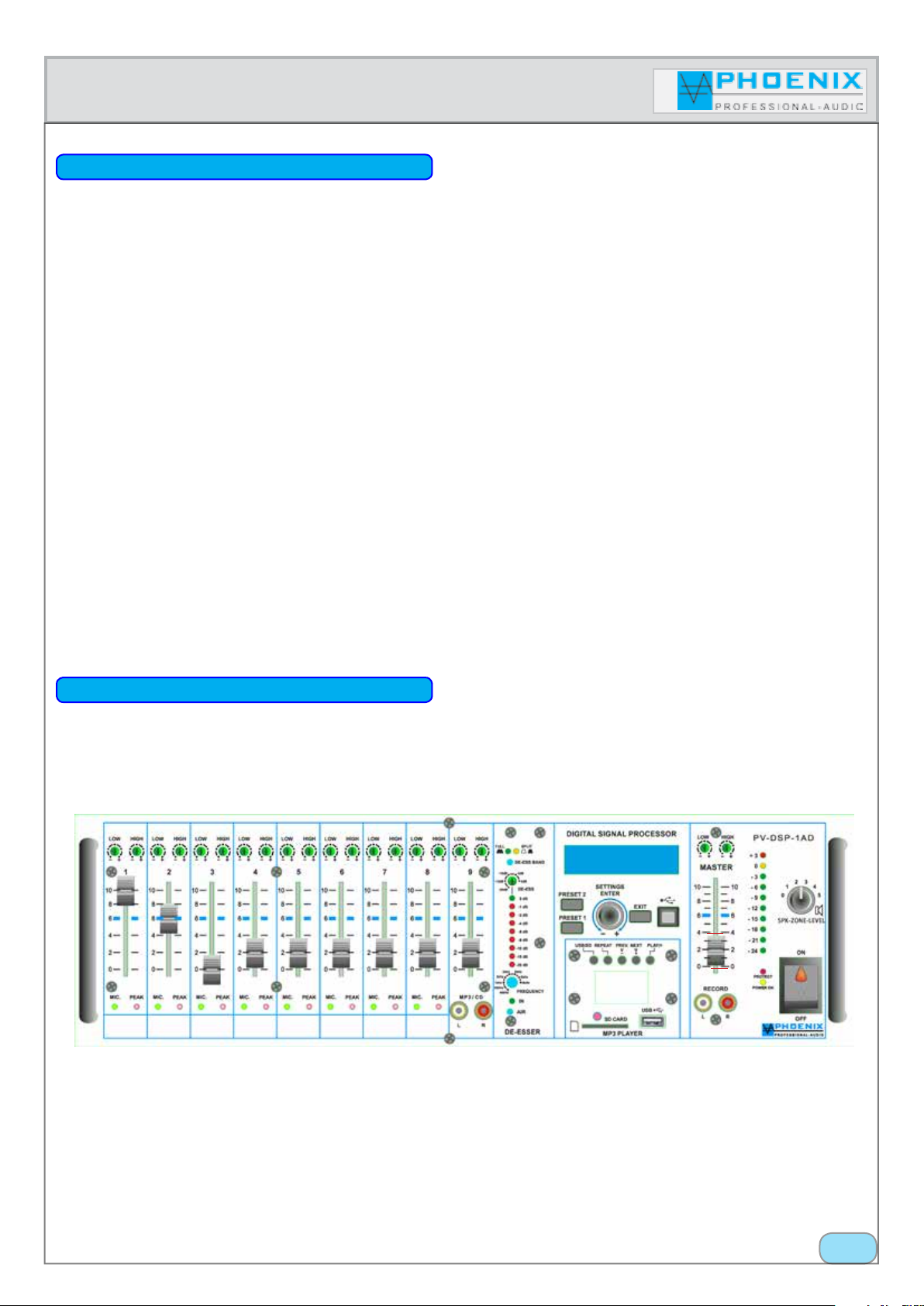
FRONT SIDE OF THE AMPLIFIER
“Copyright 2015, Phoenix Professional Audio GmbH, www.phoenix-pa.com“
Phoenix logo is registered at the German Patent- and Trademark Office ( TM)
All brands are property of their respective owners.
5.
Page 7
Instruction manual
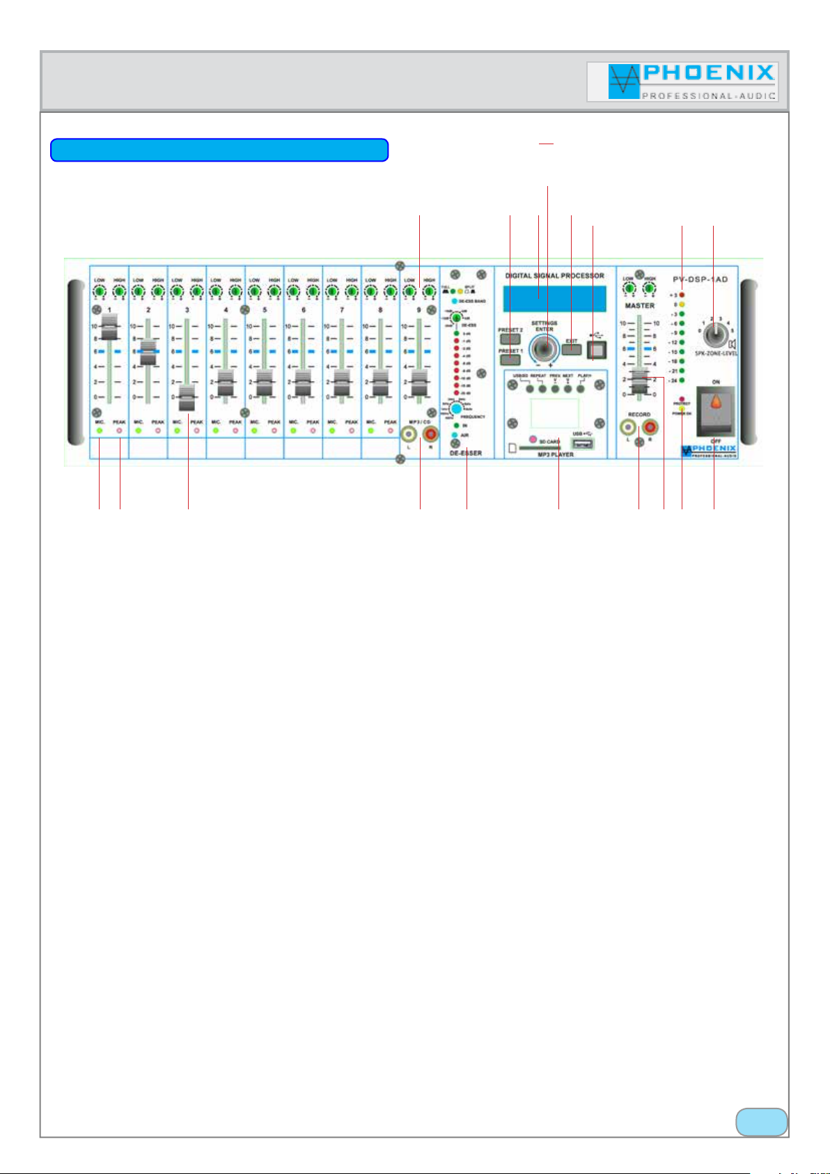
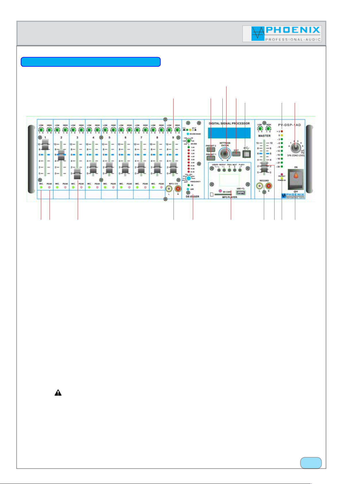
FRONT SIDE OF THE AMPLIFIER
TM
14
11 12 13 15 16
1 2 3 4 5 6 7 8 9 10
17 18
1. CONTROL LEDs AUTOMATIC SYSTEM
Green LED indications light when the automatic mic. system allows an input signal. If the input is not responded, the green
control LED remains dark and the input remains closed. Please possibly consider the DIP switch position.
2. CONTROL LEDs PEAK
Red LED indications light when the input signal is too high and the input is overridden. In case of override please change GAIN
LEVEL or DIP switch position (MIC.-LINE).
3. CHANNEL VOLUME CONTROL 1 to 9
These controls (level slide controls) determine the volume of the inputs 1 to 9. Please consider the volume controls (limiters) in
the display (settings 1-4 VOL, DSP) and the MASTER control or GAIN-LEVEL potentiometer at the rear side.
4. LINE INPUT
Line input (0 dB) with level slide controls, LF and HF-EQ controls for f.i. CD player feed etc. (front input).
5. DeEsser (basics)
If a transmission of the human voice is carried out, it is often necessary for aesthetic reasons, subsequently to raise or to drive
the high frequency parts of the reproduction (approx. 2 kHz to 8 kHz) by means of an equalizer.
Thereby the voice gets a more robust sound or more presence.
Also for pure speech transmissions thereby a voice appears more direct to the most listeners and attracts more attention with
the same volume.
A problem occurs with raising the high frequencies of a speech transmission, as the voiceless sibilants (s, ss, ß, sch, z, tz) almost
exclusively consist of such frequencies, by amplifying these areas they are reproduced disproportionally loud.
Besides this, this effect is intensified by the often used compression of the speech signal, as these sounds are indeed perceived
as loud, but regarding the technical signal level they are low and can hardly be driven by the compressor.
Insofar a reproduction processed in this way sounds very unpleasant, as the sibilants are noticed disproportionally loud and
very intrusive.
“Copyright 2015, Phoenix Professional Audio GmbH, www.phoenix-pa.com“
Phoenix logo is registered at the German Patent- and Trademark Office ( TM)
All brands are property of their respective owners.
6.
Page 8
TM
Instruction manual
DeEsser
5. (5.2) DeEsser (function FULL/ automatic)
The De-Esser located in the amplifier system in the system setting „FULL“ at first separates the lower from the problematic
middle and upper frequencies automatically (in the frequency range 800 Hz to 8 kHz) and then compresses the last, whereby
too loud sections are automatically lowered in the level (please consider the setting „ATTENUATION“ Poti No. 5.3). Afterwards
both signals are mixed together again. The result is a present and good sounding reproduction of the human voice without
obtrusive sibilants (s, ss, ß, sch, z, tz).
In system operation of the DeEsser „FULL“ the yellow control LED lights up.
5. (5.3) DeEsser (function SPLIT/ BAND manual)
By pressing the button „DE-ESS BAND“ the DeEsser is activated in SPLIT modes, the green control LED lights up.
With manual setting of the DeEsser the lower frequency (start frequency) has to be set with potentiometers No. 5.5. Above
this frequency the DeEsser is active.
EXAMPLE:
With Poti No. 5.5 the start frequency is set to the value 3 kHz, that means the frequency band above 3 kHz is controlled by the
DeEsser and the powerful, obtrusive sibilants (s, ss, ß, sch, z, tz) are reduced for the value (0 dB to -20 dB) set with the potentiometer
No. 5.3 (attenuation).
IMPORTANT:
To reach a better sound result above the 12 kHz frequencies, it is recommended, always to work with active DeEsser and additional
function „AIR“.
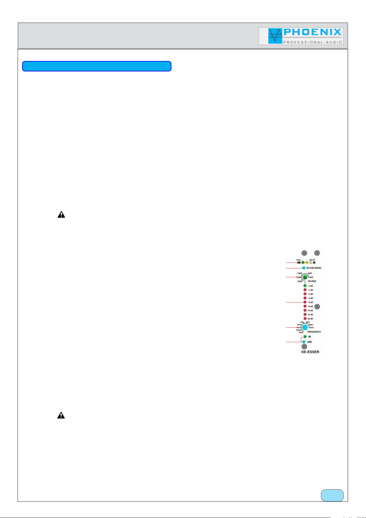
5.1 Operating mode control LED`s
The green LED lights, when the DeEsser is in „FULL“ mode, the yellow LED lights in operating
mode „SPLIT“.
5.2 Selector switch „DE-ESS BAND“ (MODES: FULL/SPLIT)
By operating the selector switch the favoured MODE TYPE can be shifted between „FULL“ and
„SPLIT“ (band).
5.1
5.2
5.3
5.4
5.3 ATTENUATION
By turning the potentiometer the favoured attenuation of the (s, ss, ß, sch, z, tz) sounds is adjusted. The set attenuation affects both MODE types „FULL“ and „SPLIT“ equally. The range of the
drop is between 0 dB and -20 dB.
5.5
5.6
5.4 LED INDICATION (ATTENUATION)
The LED chain shows LIVE the current strength of the attenuation in the range of 0 dB (no attenuation, green LED lights) up to -20 dB (all LEDs light red).
5.5 FREQUENCY (start frequency)
In the „DE-ESS BAND“ SPLIT mode the lower start frequency has to be adjusted.
Referring to his, you adjust with potentiometers No. 5.5 the most suitable frequency, the attenuation of the sibilants by the DeEser is done above the set start frequency.
IMPORTANT:
In the mode „FULL“ the potentiometer „FREQUENCY“ has no function.
5.6 DeEsser AIR mode
By pressing the button „AIR“ „Modes AIR“ is activated and the green control LED lights up. Modes AIR has the effect that the frequency band above the 12 kHz is not affected by the DeEsser.
To reach a better sound result above the 12 kHz frequencies, it is recommended, always to work with
active DeEsser and function „AIR“.
“Copyright 2015, Phoenix Professional Audio GmbH, www.phoenix-pa.com“
Phoenix logo is registered at the German Patent- and Trademark Office ( TM)
All brands are property of their respective owners.
7.
Page 9
Instruction manual
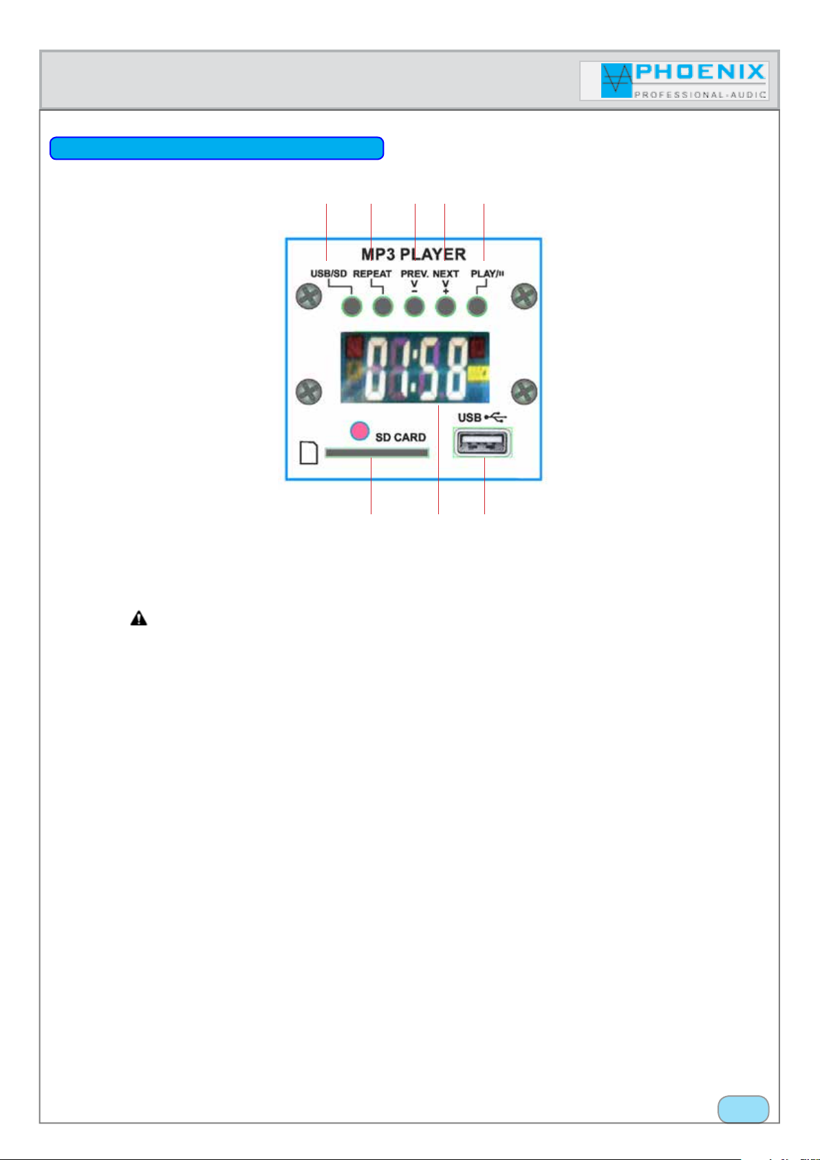
MP3 player No. 6
1 2 3 4 5
TM
6 7 8
1. USB/SD
This button is used for shifting between USB operation or SD card operation. A single medium, that means an USB stick (USB
flash drive pen) or a SD card is „individually“ automatically recognized by the system.
IMPORTANT:
The function is only given when simultaneously two storage mediums are located in the USB player.
2. REPEAT
By short pressing the button REPEAT, „ONE appears on the display and the current song is repeated. By pressing again, „ALL“
appears on the display and all songs located on the USB stick are repeated. The function is switched off by holding the REPEAT
button for approx. 3 seconds, then the device changes to normal PLAY MODE.
3. PREV & (-V) FUNCTIONS
The button „PREV & (-V)“ has two separate functions:
1.- by short pressing the „PREV“ button it is switched to the previous song and automatically played.
2.- by pressing the button „PREV & (-V)“ for approx. 3 seconds the volume of the MP3 player is decreased (-volume), on the
display appears the current volume number (between 0 and 30).
4. NEXT & (+V) FUNCTIONS
The button „NEXT & (+V) has two separate functions:
1.- by short pressing the „NEXT“ button it is switched to the next song and automatically played.
2.- by pressing the button „NEXT& (+V)“ for approx. 3 seconds the volume of the MP3 player is increased (+volume), on the
display appears the current volume number (between 0 and 30).
5. PLAY & II (Pause) FUNCTIONS
By pressing the PLAY button a song is started. Press the button while a song is played, the reproduction is stopped. „PAUSE
function“: press the button again and the reproduction is started again.
“Copyright 2015, Phoenix Professional Audio GmbH, www.phoenix-pa.com“
Phoenix logo is registered at the German Patent- and Trademark Office ( TM)
All brands are property of their respective owners.
8.
Page 10
Instruction manual
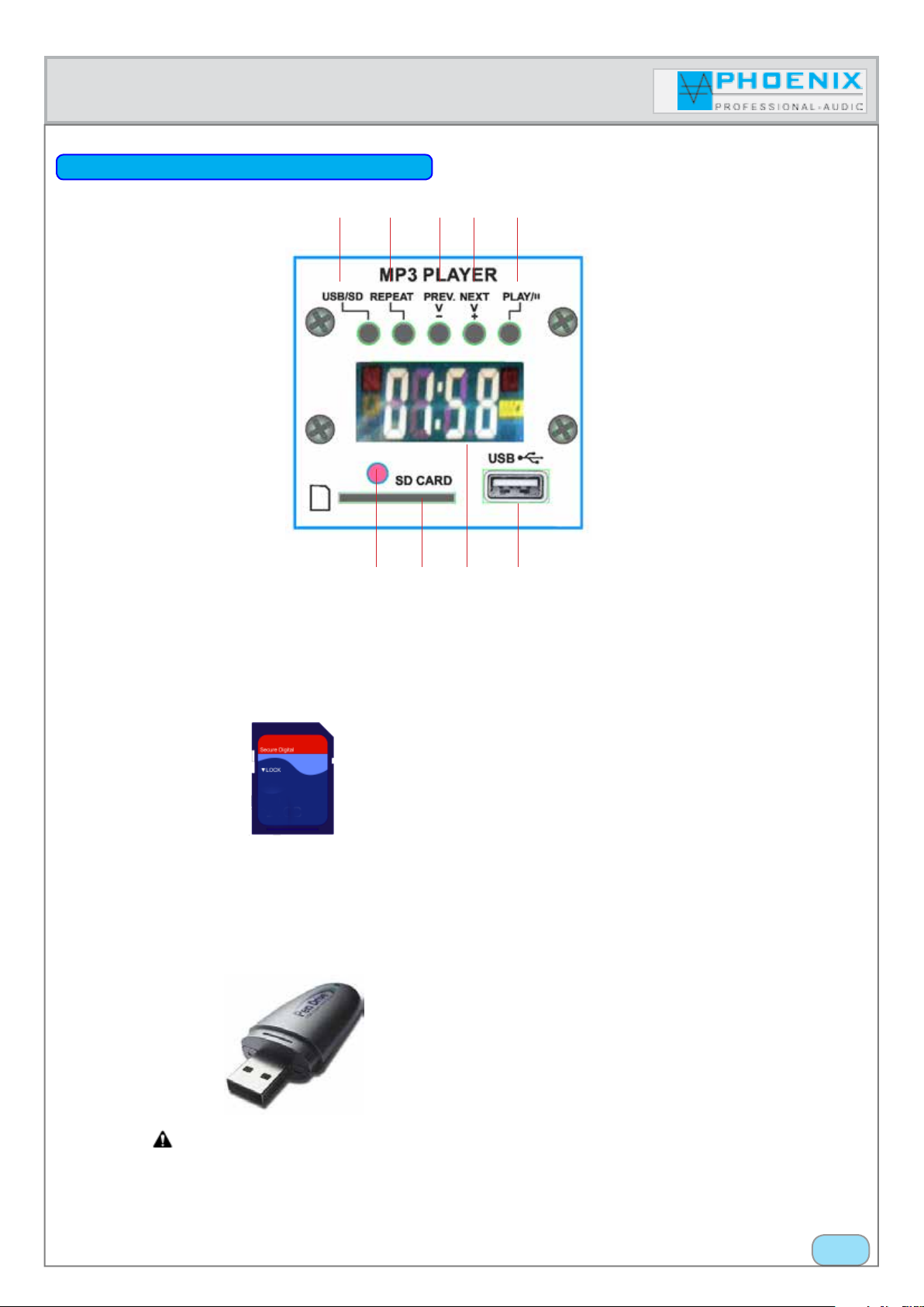
MP3 player No. 6
1 2 3 4 5
TM
6 8 9
7
6. IR REMOTE CONTROL INPUT
Remote control infrared signal input. To guarantee a correct remote control function, the so-called „SIGHT CONTACT“ between
the amplifier and the remote control shall be given.
7. SD CARD SLOT
SD card slot
8. LC DISPLAY
On the display information for the user for operation of the MP3 player is indicated.
9. USB SLOT
USB slot for an USB stick (USB flash drive pen)
IMPORTANT:
The MP3 player has no FILE management function; it is recommended to play compositions on the USB stick without FILES.
“Copyright 2015, Phoenix Professional Audio GmbH, www.phoenix-pa.com“
Phoenix logo is registered at the German Patent- and Trademark Office ( TM)
All brands are property of their respective owners.
9.
Page 11
Instruction manual
TM
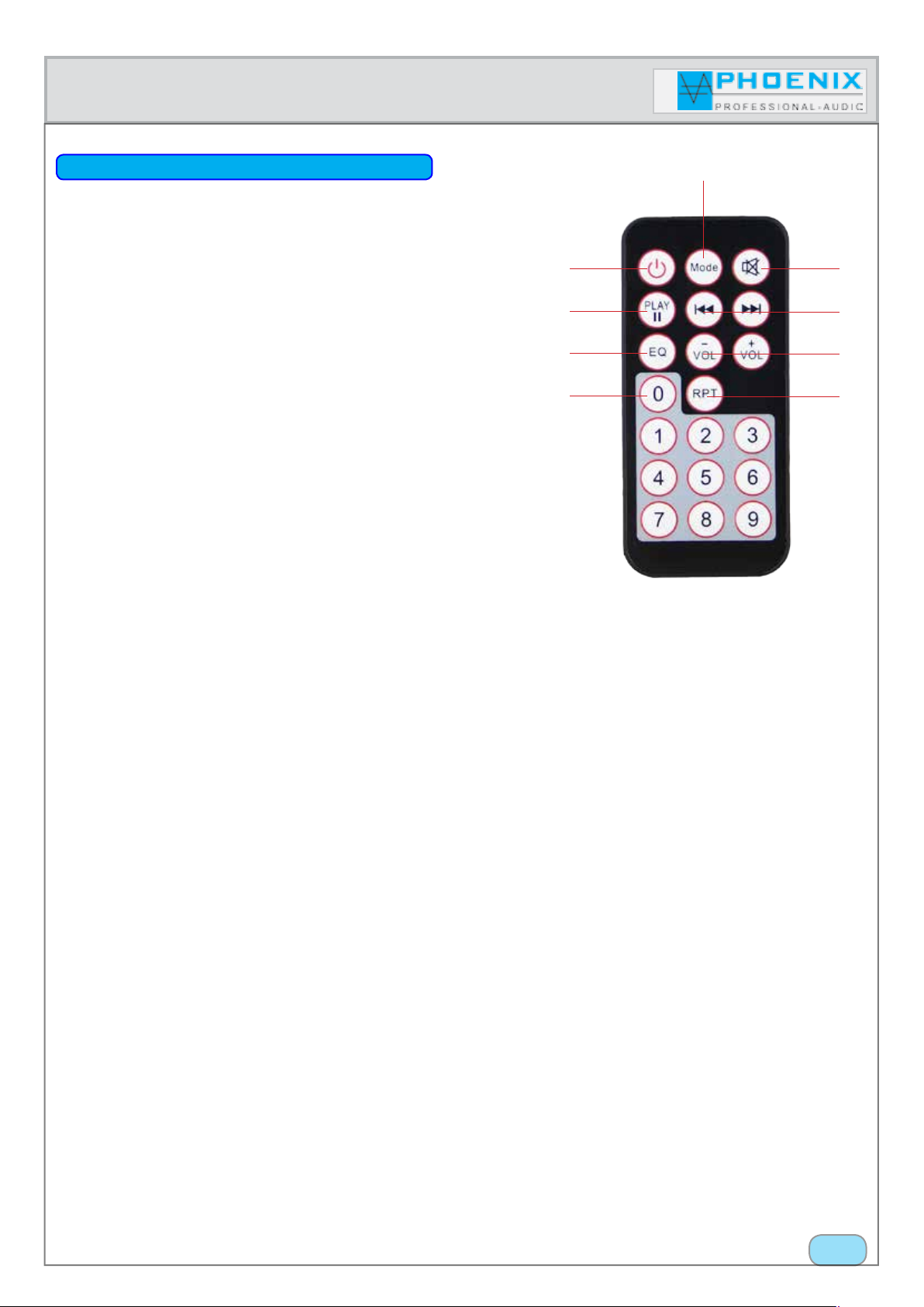
REMOTE CONTROL OF THE MP3 PLAYER
1. MODE
SLOT selection switch, this is used for shifting between USB operation or
SD card operation.
2. ON- and OFF SWITCH (ON/OFF)
After activating this switch the MP3 player can be switched ON and OFF.
3. PLAY & II (Pause) FUNCTIONS
By pressing the PLAY button a song is started. Press the button while a
song is played, the reproduction is stopped. „PAUSE“ function: press the
button again and the reproduction is started again.
4. EQ
The integrated MP3 player has 6 fix audio DSP, EQ presets. By repeated
activation of the EQ-button it is shifted between the six presets. The current audio DSP preset is indicated on the display. Display indication of
the MP3 player: E1 to E6.
1
2
3
4
5 6
9
8
7
5. KEYBOARD 0-9
Block keyboard for fast selection of the compositions.
6. RPT - REPEAT
By short pressing the button REPEAT, „ONE“ appears on the display and the current song is repeated. By repeated pressing,
„ALL“ appears on the display and all songs located on the USB stick are repeated. The function is switched off by holding the
REPEAT button for approx. 3 seconds, then the device changes to normal PLAY MODE.
7. VOL-
By pressing the button „VOL-“ the volume of the MP3 player is decreased (-volume), on the display appears the current volume
number (between 0 and 30).
7.1. VOL+
By pressing the button „VOL+“ the volume of the MP3 player is increased (+volume), on the display appears the current volume number (between 0 and 30).
8. Ivv wwI
By short pressing the „wwI“ button it is switched to the next song, by short pressing the „Ivv“ button it is switched to the
previous song and played automatically.
9. MUTE
By pressing the MUTE button the reproduction is interrupted, but the program or the current song is not stopped by the system,
it continues in the system. By pressing the button again, the reproduction of the song is activated.
“Copyright 2015, Phoenix Professional Audio GmbH, www.phoenix-pa.com“
Phoenix logo is registered at the German Patent- and Trademark Office ( TM)
All brands are property of their respective owners.
10.
Page 12

Instruction manual
FRONT SIDE OF THE AMPLIFIER
TM
14
11 12 13 15 16
1 2 3 4 5 6 7 8 9 10
17 18
10. RECORD OUTPUT
Unbalanced connected (0 dB), is used to connect recording devices. The signal which is available for recording, is the signal sum
of the microphone- and sound carrier inputs before the sound- (EQ)- and MASTER volume control.
11. MASTER SECTION
With this control the master volume can be adjusted, raised or driven. Please consider the digital volume control in DSP audio
(limiter) in the system display (settings VOL for PRESETS 1 and 2).
12. CONTROL LED`s, PROT and PWR OPERATION DISPLAY
When the PROTECT control indication lights up without input signal, possibly there are system oscillations or other interferences. Disconnect the load and reduce the amplification to zero. When the LED continues to light, possibly the amplifier has to be
maintained.
13. MAINS ON-/OFF SWITCH WITH OPERATION DISPLAY
After activation of this switch the device is ready for use. Operating voltage 230 VAC/50-60 Hz.
14. 2-BAND EQ
Separate LF- and HF control of the individual microphone- or LINE inputs and MASTER SECTION. At the rear side please select
the DIP switches between MIC.- and LINE sensitivity.
15. PRESET 1 and PRESET 2 switch with LED indication
Manual shift of the presets 1 and 2, if a manual shift of the PRESETS shall be carried out, the current condition is indicated by the
control LED PRESET 1 or PRESET 2 or the „CLEAR TEXT“ PRESET name on the display.
16. DISPLAY
Multifunctional display with menu navigation and indication for all guided settings in the system by the SETTING/ENTER button
(manual programming of the device).
“Copyright 2015, Phoenix Professional Audio GmbH, www.phoenix-pa.com“
Phoenix logo is registered at the German Patent- and Trademark Office ( TM)
All brands are property of their respective owners.
11.
Page 13
Instruction manual
FRONT SIDE OF THE AMPLIFIER
TM
14
11 12 13 15 16
1 2 3 4 5 6 7 8 9 10
17 18
17. SETTINGS/PUSH/ENTER BUTTON
To change into the programming mode, shortly press the button ENTER, the display changes over. By turning the PUSH/ENTER
button you change between the programs. All settings are permanently saved and remain preserved also in case of interruption
of the power supply. After the carried out programming and by pressing the button EXIT, on the display a standard indication
with feedback limiter status display and the clear text name of the presets is indicated.
18. EXIT BUTTON
By pressing this button you get from the main program to the sub program or back to the standard display indication.
19. USB INTERFACE
Is used for connection to a PC and programming by the control software MWL-CONTROL.
20. LEVEL INDICATION
The level indication lights up when the input signal exceeds -24 dB. If there is no indication, check the amplification settings and
increase the gain if necessary. Check the input connections and the audio source for signals. When the PROT-LED lights or the
level indication shows +3 dB, although no signal is indicated, check the input- and output wiring.
21. SPEAKER ZONE 1 (SEPARATE SPEAKER LINE)
Individual speaker lines for f.i. control speaker with 100V output and separate volume controls (step switch, maximum load is
equal to the maximum amplifier gain).
IMPORTANT:
The first speaker zone „SPEAKER ZONE 1“ is connected with the internal amplifier power final stage (200 Watt).
“Copyright 2015, Phoenix Professional Audio GmbH, www.phoenix-pa.com“
Phoenix logo is registered at the German Patent- and Trademark Office ( TM)
All brands are property of their respective owners.
12.
Page 14

Instruction manual
CONNECTIONS OF THE AMPLIFIER
TM
11 12 13 14 15
1 2 3 5 7 8 9
4
10
1. 230VAC INPUT BUSH
IEC socket for connection to the 230VAC mains supply with glass fuse.
2. RJ-45 REMOTE CONTROL INPUT
Remote control input (control panel), optional device. Is used for manual remote selection of the presets 1 and 2.
3. RELAY CONTROL PANEL (INFO OUT PRESET-2)
Floating contacts with automatic shift by the preset-2 position. Is used for intrusion of an additional speaker line with preset-2
selection, like f.i. when programming the amplifier for the Sunday mass, Christmas „church is full“ for PRESET-2 program sequence.
4. MIX OUT (audio matrix output MAINSUM-2)
The MIX-OUT output is constructed balanced with signal routing for input 9 (LINE, CD) and all inputs 1 to 8, which are allocated
by programmer No. 3 (MAINSUM-2) and programmer No. 2 (MAINSUM-1) inputs.
Besides this, the position of the programmer No. 4 affects the output MIX-OUT as follows:
OUT2 PRE/POST GATE (switch No. 1@programmer No. 4)
Position (above) OFF, all input channels allocated by the programmer-3 (MAINSUM-2) are standard routed according to the
automatic system and MASTER slide control. POST-GATE position.
Position (below) ON, all input channels allocated by the programmer No. 3 (MAINSUM-2) are routed before the automatic
system and MASTER slide control. PRE-GATE position.
5. LINE OUT (POST MASTER OUT/ MAINSUM-1)
Transformer-balanced linear (after EQ and Master) output LINE (0 dB).
6. LINE OUT (PRE MASTER OUT)
Transformer-balanced linear (before EQ and Master) output LINE (0 dB).
“Copyright 2015, Phoenix Professional Audio GmbH, www.phoenix-pa.com“
Phoenix logo is registered at the German Patent- and Trademark Office ( TM)
All brands are property of their respective owners.
13.
Page 15

Instruction manual
CONNECTIONS OF THE AMPLIFIER
TM
11 12 13 14 15
1 2 3 5 7 8 9
4
10
7. GROUND LIFT (SEPARATE PER OUTPUT)
Typical uses in mass-hum loops, with multiple grounded audio connections, especially when two so-called LINE-LINE devices
are coupled together with audio line.
8. LINE OUT (PRE MASTER OUT)
Transformer-balanced linear (before EQ and Master) output LINE 0 dB.
9. LINE IN (PRE MASTER)
Linear (before EQ and Master) balanced input to Jack bush (LINE level, 0 dB).
10. LINE CD IN-9
Unbalanced RCA connection (LINE level, +0 dB). The connectors are unbalanced connected and are suitable for stereo sound
carrier, L+R are internally interconnected via an OP 1/1.
The volume- and LF/HF control is done at the front side with front slide control or LF/HF with spindle trimmers countersunk in
the front plate.
11. SPEAKER OUTPUTS
The 100V speakers are connected at the clamp 100V and COM pin. Low-ohmed speakers with an impedance of 8 or 4 Ohm are
connected to the clamps 8 Ohm or 4 Ohm and COM.
Attention:
Only either 100V speakers OR low-ohmed speakers can be connected - simultaneous use is not possible.
“Copyright 2015, Phoenix Professional Audio GmbH, www.phoenix-pa.com“
Phoenix logo is registered at the German Patent- and Trademark Office ( TM)
All brands are property of their respective owners.
14.
Page 16

Instruction manual
CONNECTIONS OF THE AMPLIFIER
The illustration No. 1 shows the speaker output clamp
with zone-OUT-1.
Speaker output ZONE 1 is supplied from the internal power final stage.
The output is 100V with the maximum power of 200 Watt. Drawing: YEL-
LOW=100V, BLACK=COM.
A direct speaker output is supplied from the first, internal power final stage. The output is 100V with the maximum power of 200 Watt. Drawing:
BLUE=100V, BLACK=COM.
Please consider that the ZONE-1 output and the direct speaker output
are supplied from the same power final stage. The connected LOAD
in the ZONE 1 and to the direct output shall totally not exceed more
than 200 Watt.
TM
Attention:
To the direct speaker output only either 100V speakers OR low-ohmed speakers can be connected - the simultaneous
use is not possible and leads to system shutdown or can lead to the destruction of the power final stage.
Useful information
For the speaker zone extention a speaker zone control panel type: SW-6 is available. By the outputs „coupling“ of the amplifier
PV-DSP-1A(C)D.XX (COM, 4/8 Ohm, 50V, 70V and 100V) with inputs of the SW-6 the setup of additional 6 speaker zones with
ON/OFF switch and separate volume control is possible.
“Copyright 2015, Phoenix Professional Audio GmbH, www.phoenix-pa.com“
Phoenix logo is registered at the German Patent- and Trademark Office ( TM)
All brands are property of their respective owners.
15.
Page 17

Instruction manual
SPEAKER OUTPUTS
TM
Church front sound
internal AMP1 equalization 1
Gallery sound ZONE 1
by AMP-1 with separate
volume control.
Church exterior sound
AMP1 equalization 1
Automatic activation
with preset No. 2.
16.
Page 18

Instruction manual
CONNECTIONS OF THE AMPLIFIER
TM
11 12 13 14 15
1 2 3 5 7 8 9
4
10
12. CONTROLLABLE SPEAKER OUTPUT
The controllable output No. 12 is coupled with the internal final stage. The maximum load is 200 Watt/100 Volt.
ATTENTION:
Please consider that the ZONE-1 output and the direct speaker output are supplied from the same power final stage.
The connected LOAD in the ZONE-1 and to the direct output shall totally not exceed more than 200 Watt.
13. AUDIO INPUTS 1 to 8
At the device´s rear side there are 8 x XLR audio input bushs (No. 15). The inputs are designed balanced +2, -3, 1- shielding (see
drawing). The input sensitivity (GAIN) for each input can be adjusted at the rear side. The input volume is adjusted at the device´s
front side with separate slide control and 2-element EQ.
ATTENTION:
All microphone inputs have a shiftable phantom power +48VDC (DIN/IEC norm). If unbalanced, dynamic microphones shall be
connected to the audio inputs, a coupling condenser has to be added or the phantom power has to be switched off.
Balanced inputs: Isolate the wire lines for 6 mm and connect them as
shown with the clamps. Tighten the screws firmly.
1 GND
2 +IN
3 -IN
Unbalanced inputs: Isolate the wire lines for 6 mm and connect them as shown
with the clamps. The middle pin has to be connected with the shielding pin as
shown. Tighten the screws firmly.
“Copyright 2015, Phoenix Professional Audio GmbH, www.phoenix-pa.com“
Phoenix logo is registered at the German Patent- and Trademark Office ( TM)
All brands are property of their respective owners.
17.
Page 19

Instruction manual
CONNECTIONS OF THE AMPLIFIER
TM
11 12 13 14 15
1 2 3 5 7 8 9
4
10
14. GAIN CONTROL
Each input channel has an independent gain control.
DIP switch (position: MIC) ON-position: -40 dB/-15 dB, DIP switch (position: LINE) OFF-position: -15 dB/+5 dB.
15. DIP SWITCH (MIC. LINE / PHANTOM-POWER / FILTER HPF-100 Hz)
Each input channel has a DIP switch, therefore the following conditions can be selected:
DIP-1 (ON): input is supplied with 24VDC phantom voltage for condenser microphones.
DIP-1 (OFF): phantom voltage is deactivated.
DIP-2 (ON): input is set to the microphone input sensitivity.
DIP-2 (OFF): input is set to the LINE input sensitivity.
DIP-3 (ON): input low cut filter (100 Hz) to remove low frequencies, parasitic noises and phase shift is activated. DIP-3 (OFF): the
highpass filter (low cut filter, 100 Hz) is deactivated.
“Copyright 2015, Phoenix Professional Audio GmbH, www.phoenix-pa.com“
Phoenix logo is registered at the German Patent- and Trademark Office ( TM)
All brands are property of their respective owners.
18.
Page 20

Instruction manual
SETTINGS IN AUTOMATIC/MAINSUM-1 AND MAINSUM-2
Programmer-2
MAINSUM-1
TM
Programmer-1
AUTOMATIC ON/OFF
Programmer-5
PRIORITY & CONFERENCE
AUTOMATIC JUSTIFICATION
Programmer-3
MAINSUM-2
TIME
Programmer-4
SENSITIVITY
LINE/CD JUSTIFICATION
ATTACK
AUTOMATIC JUSTIFICATION
DESCRIPTION PROGRAMMER 2 (MAINSUM 1) DIP-MATRIX
With the PROGRAMMER-2 switch block the individual channels 1 to 8 can be allocated to the internal amplifier final stage for
the reproduction of the speakers connected at the amplifier [MAINSUM-1].
The carried out setting by the PROGRAMMER-2 affects the output No. 5 (OUTPUT POST-MASTER).
In the factory setting all eight inputs are routed to the internal amplifier by PROGRAMMER-2.
Useful information
Programmer 2, (DIP-MATRIX) settings based upon the input channel No. 1 (MIC.-LINE 1) input.
Setting No. 1 (mute)
The signal fed at input 1 is muted.
Please consider the following settings (illustrations below).
Programmer 2 Programmer 3
“Copyright 2015, Phoenix Professional Audio GmbH, www.phoenix-pa.com“
Phoenix logo is registered at the German Patent- and Trademark Office ( TM)
All brands are property of their respective owners.
19.
Page 21

TM
Instruction manual
SETTINGS IN AUTOMATIC/MAINSUM-1 AND MAINSUM-2
Explanation of the function:
The signal of the input 1 is excluded by (programmer 1), separated from the internal amplifier final stage and not switched
further by (programmer 3) to the output MIX-OUT.
The signal is thereby muted. The function allows a deactivation of the system inputs against an unauthorized use of the inputs.
Useful information
Factory setting: groups and functions in AUTOMATIC, MAINSUM 1 and MAINSUM 2.
PROGRAMMER 1 PROGRAMMER 2 PROGRAMMER 3
Explanation of the function:
In the PROGRAMMER-1 all input channels 1 to 8 are connected with the digital AUTOMATIC SYSTEM.
All inputs (MIC.-LINE) 1 to 8 are allocated to the MAINSUM 1 in [PROGRAMMER-2].
The input 8 is allocated by the DIP switch position in PROGRAMMER 2 to the MAINSUM 1 and in PROGRAMMER-3 to the
MAINSUM 2 (MIX-OUT) (f.i. connection subwoofer).
The input 9 (LINE-IN) is always allocated to the MAINSUM 1 and MAINSUM 2 and is not subject to the automatic function.
DESCRIPTION PROGRAMMER-3 (MAINSUM 2) DIP-MATRIX
With the PROGRAMMER-3 switch block individual channels 1 to 8 can be allocated to the MAINSUM-2, that means the selected channels are allocated to [MAINSUM-2] and reproduced at the output MIX-OUT. No reproduction by the connected speakers and audio outputs.
Programmer-2
MAINSUM-1
Programmer-1
AUTOMATIC ON/OFF
Programmer-3
MAINSUM-2
Programmer-5
PRIORITY & CONFERENCE
“Copyright 2015, Phoenix Professional Audio GmbH, www.phoenix-pa.com“
Phoenix logo is registered at the German Patent- and Trademark Office ( TM)
All brands are property of their respective owners.
AUTOMATIC JUSTIFICATION
TIME
Programmer-4
SENSITIVITY
LINE/CD JUSTIFICATION
ATTACK
AUTOMATIC JUSTIFICATION
20.
Page 22

TM
Instruction manual
SETTINGS IN AUTOMATIC/MAINSUM-1 AND MAINSUM-2
Useful information
System setting of the groups MAINSUM 1 and MAINSUM 2 for speech and music reproduction (system with active woofer and digivoice system, BEAM-STEERING systems).
Music source
Transmission by all speaker systems
and woofer.
Better music reproduction.
K2-20REG
Altar room sound
equalization by internal
amplifier DSP system.
Feedback control by FBS.
MEX-1-XX serie+MPL-2
The microphone signal is transferred by all
speaker systems without woofer.
Better speech intelligibility.
K4-40F
Gallery sound DSP-OUT-2 equalization by additional amplifier, f.i.
WM-200DT
DAS-1000
Active SUB bass DSP
Reproduction of the music
signal without microphone
signal (speech).
Better speech intelligibility.
Digivoice.110B.8 DSP
BEAM STEERING system
main sound f.i. nave.
Equalization by internal DSP
system in the Digivoice.
PROGRAMMER 1 PROGRAMMER 2 PROGRAMMER 3
In this DIP-PROGRAMMER position signals which are fed to input 8 and LINE-IN, are transferred to all speaker systems.
Microphone signals, however, are transferred to all speaker systems except DAS-1000 (SUBBASS).
The input No. 8 has been excluded from the automatic function by the PROGRAMMER 1.
“Copyright 2015, Phoenix Professional Audio GmbH, www.phoenix-pa.com“
Phoenix logo is registered at the German Patent- and Trademark Office ( TM)
All brands are property of their respective owners.
21.
Page 23

Instruction manual
SETTINGS IN AUTOMATIC SYSTEM (DSDF)
DESCRIPTION PROGRAMMER 1 (AUTOMATIC ON/OFF)
TM
The PV-DSP-1AD.9.2 (third generation) has a digital automatic (DSDF),
automatic connection of the recorded microphones with automatic control of the input with BARRIER-GATE, GATE-OPEN and
GAIN-CONTROL.
The system (DSDF) is based upon the measurement of the stronger wanted signal by the temporary signal delay (SIGNAL-DELAY
TIME) principle.
IMPORTANT:
All DIP switches are located in the interior of the amplifier. For the hardware configuration please open the small cover which is
located in the upper part of the amplifier´s cover.
With the PROGRAMMER-1 switch block the automatic function of the mixer each input channel 1 to 8 can be
OFF, not tilted) or
operation without automatic. In the front side of the amplifier, all channels excluded from the automatic system are shown by
the green LED (IMPORTANT: and each according to the setting in PROGRAMMER-4 the last recorded channel).
The illustration shows programmer No. 1 with position of the DIP switches „ALL INPUTS“ are managed by the automatic system
[OFF-position of the DIP switch].
deactivated
(pos. ON, tilted downwards), when f.i. the input is used as LINE input and shall be taken into
DIGITAL SIGNAL DELAY FIELD
system, that means an
activated
(pos.
The illustration shows programmer No. 1 with position of the DIP switches „ALL INPUTS“ are excluded from the automatic sys-
tem. The selective choice of the inputs for AUTOMATIC ON/OFF is of course possible [ON-position of the DIP switch].
Useful information:
With programmer No. 1 the automatic function of the mixer can be adjusted activated (position OFF) or deactivated (position
ON). If f.i. channel 1 programmer-1 @ switch 1) shall be used as LINE input, it is senseful to deactivate the automatic function of
the mixer there, f.i. to reach a better recording quality with RECORDING.
Upon delivery of the amplifier all input channels are defined as automatic, the programmer-1 switches are in position OFF.
IMPORTANTT:
If the amplifier or the priorities shall be adjusted or used in conference mode, the respective channels have to be set to [OFF]
by programmer 1 (upper DIP position, AUTOMATIC ACTIVE).
“Copyright 2015, Phoenix Professional Audio GmbH, www.phoenix-pa.com“
Phoenix logo is registered at the German Patent- and Trademark Office ( TM)
All brands are property of their respective owners.
22.
Page 24

Instruction manual
SETTINGS IN AUTOMATIC SYSTEM (DSDF)
Active inputs
Not active inputs
TM
Sound source
f.i. chorister
The justification of the automatic system is located in the interior of the device, please remove the upper small cover. By turning
the respective trimmers the parameter for TIME / ATTACK can be changed in the automatic.
AUTOMATIC TIME JUSTIFICATION
The time [GATE-OPEN-TIME] of the active microphones is changed.
AUTOMATIC ATTACK JUSTIFICATION
The reaction speed or [BARRIER-GATE-GATE-OPEN] of the internal automatic shift is adapted to the input signal or the sensi-
tivity.
Programmer-4
Programmer-5
PRIORITY & CONFERENCE
“Copyright 2015, Phoenix Professional Audio GmbH, www.phoenix-pa.com“
Phoenix logo is registered at the German Patent- and Trademark Office ( TM)
All brands are property of their respective owners.
AUTOMATIC JUSTIFICATION
TIME
SENSITIVITY
LINE/CD JUSTIFICATION
ATTACK
AUTOMATIC JUSTIFICATION
23.
Page 25

Instruction manual
SETTINGS IN AUTOMATIC/MAINSUM-1 AND MAINSUM-2
Programmer-5
PRIORITY & CONFERENCE
AUTOMATIC JUSTIFICATION
TIME
TM
Programmer-4
SENSITIVITY
LINE/CD JUSTIFICATION
ATTACK
AUTOMATIC JUSTIFICATION
DESCRIPTION PROGRAMMER-4
Standard switch position upon delivery:
Switch No. 1 „
OUT2 PRE/POST GATE“ a
nd switch No. 2 „
AUTO/MANUAL“
in the position OFF
Switch No. 3 ATTENUATION and switch No. 4 programmer in the position ON
OUT2 PRE/POST GATE (switch No. 1@ PROGRAMMER-4)
Position (above) OFF, all input channels allocated by the DIP-2 (MAINSUM-2) are standard routed according to automatic sys-
tem and input slide contol. POST-GATE position.
Position (below) ON, all input channels allocated by the DIP-2 (MAINSUM-2) are routed before the automatic system and input
slide control. PRE-GATE position.
AUTO/MANUAL (switch No. 2@ PROGRAMMER-4)
In the position (above) OFF (M.AUTO) the mixer is programmed to AUTOMATIC function.
In the position (below) ON (MANUAL) the
AUTOMATIC function is switched off
, the mixer works as conventional STANDARD
MIXER, without automatic FUNCTION.
ATTENUATION (switch No. 3@ PROGRAMMER-4)
With switch No. 3 in DIP-4 the not active audio inputs can acoustically be attenuated:
Po s . OFF (above) -15 dB attenuation,
Po s . ON (below) 100 % attenuation.
LAST MIC (switch No. 4@ PROGRAMMER)
Po s . OFF (above)
The recorded microphone or the input turns on and remains active until another microphone or input is recorded or activated.
Po s . ON (below)
The recorded microphone or the input turns on. After finishing the announcement, the microphone or the input is switched off
and remains in deactivated condition until it is not responded.
IMORTANT:
If you do not want to use the priority functions of the mixer (programming „conference system“), the LAST MIC. function
(switch No. 4@DIP-4) has to be shifted into the position ON.
“Copyright 2015, Phoenix Professional Audio GmbH, www.phoenix-pa.com“
Phoenix logo is registered at the German Patent- and Trademark Office ( TM)
All brands are property of their respective owners.
24.
Page 26

Instruction manual
SETTINGS FOR CONFERENCE & PRIORITY SYSTEM
Programmer-5
PRIORITY & CONFERENCE
AUTOMATIC JUSTIFICATION
TIME
TM
Programmer-4
SENSITIVITY
LINE/CD JUSTIFICATION
ATTACK
AUTOMATIC JUSTIFICATION
DESCRIPTION PROGRAMMER-5
IMPORTANT:
All DIP-switches (PROGRAMMER) are located in the interior of the amplifier. For the hardware configuration please open the
small cover which is located in the upper part of the amplifier´s cover.
IMPORTANT:
If the mixer shall be used as a „CONFERENCE SYSTEM“ with priority levels, the input used for the „conference“, PROGRAMMER-1
switch (X), has to be set to position OFF.
IMPORTANT:
If you want to use the priority functions of the mixer (conference system), the LAST MIC. function PROGRAMMER-4 switch No. 4
has to be switched into the position ON.
The priority shown in the illustration below affects the microphone inputs 1 and 2, that means microphone 1 has priority over
the microphones No. 2 to 8. Microphone 2 has a priority function over the microphones No. 3 to 8.
In this configuration priority functions of the 1st chairman and the 2nd chairman against the microphones 3 to 8, or the 1st
chairman over the 2nd chairman and the microphone input 3 to 8 are effective.
OFF
ON
“Copyright 2015, Phoenix Professional Audio GmbH, www.phoenix-pa.com“
Phoenix logo is registered at the German Patent- and Trademark Office ( TM)
All brands are property of their respective owners.
25.
Page 27

TM
Instruction manual
SETTINGS FOR CONFERENCE & PRIORITY SYSTEM
The configuration apparent in the drawing shows the automatic priority allocation of the MIC-1 to MIC-3 inputs, of course the
automatic priority allocation can be configured for all microphone inputs.
In this PROGRAMMER-5 switch position the first recorded microphones keeps priority until it is recorded. All microphones set
in the configuration remain muted.
This function provides a conference order, that means the speaker cannot be interrupted as long as he speaks.
digital recorder/protocol
Table base MS-3-XX with TALK button
Speaker
Speaker
Speaker
Speaker
Speaker
Speaker
1st chairman 2nd chairman
JUSTIFICATION OF THE SENSITIVITY OF THE INPUT LINE-IN
By the internal trimmer the sensitivity of the input No. 9 LINEIN can be adapted to the favoured level.
The justification affects the front- and rear side RCA input No.
9.
Programmer-5
PRIORITY & CONFERENCE
“Copyright 2015, Phoenix Professional Audio GmbH, www.phoenix-pa.com“
Phoenix logo is registered at the German Patent- and Trademark Office ( TM)
All brands are property of their respective owners.
AUTOMATIC JUSTIFICATION
TIME
Programmer-4
SENSITIVITY
LINE/CD JUSTIFICATION
AT TACK
AUTOMATIC JUSTIFICATION
26.
Page 28

TM
Instruction manual
PROGRAMMING WITH FIRM-SOFTWARE MWL-CONTROL
All DSP functions and settings which can be carried out by the button SETTING/ENTER, can also be carried out by the system
software MWL-Control. The advantage in software programming is the produced „PMWL FILE“, this contains all DSP settings
(project data), which later is a big advantage for possible service purposes.
Installation- and operating instructions:
The software you get after delivery by sending your contact data by mail.
After that the program MWL-Control or the file MWL-1.1.1 can be installed on the PC. After the installation, the program is
started automatically.
After the USB connection between PV-DSP-1AD.XX system and the PC the computer indicates a new device in the system. To
allow the data transfer, the correct COM interface (is indicated in the device manager) has to be adjusted in the program.
To be able to establish a connection with the amplifier, in the field „SETTINGS“ the option „CONNECTION“ has to be selected.
The program scans the available COM ports and indicates the connected devices. Port COM number is shown.
In the software appears a WINDOW with the indication: FUND MWL „ MWL has been found at port COM (XX). Please confirm by
pressing the „OK“ button. The connection between PC and amplifier system is finished.
IMPORTANT:
If during connection setup the following indication appears: „COULDN´T CONNECT TO MWL DEVICE ON PORT COM (XX)“ manually select a new COM-PORT No. from the shown COM-PORT connections from the WINDOWS DEVICE MANAGER and try it
again.
“Copyright 2015, Phoenix Professional Audio GmbH, www.phoenix-pa.com“
Phoenix logo is registered at the German Patent- and Trademark Office ( TM)
All brands are property of their respective owners.
27.
Page 29

Instruction manual
PROGRAMMING WITH FIRM-SOFTWARE MWL-CONTROL
SOFTWARE RANGE „FILE“
OPEN: A project saved on the hard disk is opened
SAVE: A project is saved on the hard disk
SAVE AS: Save a project under a new file name
EXIT: Finish project and leave software.
CONNECT COM
After the connection between PC and system, amplifier is set up, in the software main window the button
CONNECT COM XX shall light green.
TM
SAVED TO MWL
To transfer the changed settings to the PV-DSP1AD.XX,
please press the button „SAVE TO MWL“ .
The files are now saved in the PV-DSP-1AD.XX, DSP
processor.
PASSWORD
You can select between DISABLE (without password
protection) and ENABLE (all settings are protected by
password).
PRESETS
DESCRIPTION PRESET 1 and 2
In the menu „PRESETS“ the two PRESETS configurations
can be carried out, saved and recalled.
Button P1-->P2: here all settings PRESETS-1 can be
copied to the PRESETS-2.
Button P2-->P1: here all settings PRESETS-2 can be
copied to the PRESETS-1.
In the small, left window the PRESETS 1 and PRESET 2
can be renamed.
RESTORE DEFAULTS
Reset PRESETS to factory settings.
All settings and information are hereby deleted!
“Copyright 2015, Phoenix Professional Audio GmbH, www.phoenix-pa.com“
Phoenix logo is registered at the German Patent- and Trademark Office ( TM)
All brands are property of their respective owners.
/DEFAULT SETTINGS
28.
Page 30

Instruction manual
PROGRAMMING WITH FIRM-SOFTWARE MWL-CONTROL
SOFTWARE PROGRAMMING
„VOLUME“
In the range „MAIN VOLUME“ the maximum volume is
adjusted digitally.
By shifting of the analogue input sensitivity slide controls (at the device´s front side) the mixer outputs are
only affected to the maximum volume of the values set
by the DSP volume controls.
For the input sensitivity at the rear side each input analogue GAIN LEVEL are available.
SOFTWARE PROGRAMMING
„DELAY“ signal delay
Range „DELAY“ can be configured, indications in
„m“/“cm“ (distance) or in „ms“ (time delay) can be
adjusted.
TM
TIP: a minimum signal delay has a positive effect to
feedback shortage.
A signal delay allows a correct sound by delaying the
acoustic signals in a way, that also with speakers or
amplification systems allocated far from each other no
echo formation happens.
Useful information:
Please select the favoured „PRESET“.
Two PRESET configurations can be carried out for all
programming processes.
“Copyright 2015, Phoenix Professional Audio GmbH, www.phoenix-pa.com“
Phoenix logo is registered at the German Patent- and Trademark Office ( TM)
All brands are property of their respective owners.
29.
Page 31

Instruction manual
PROGRAMMING WITH FIRM-SOFTWARE MWL-CONTROL
SOFTWARE RANGE „NOISE GATE“
„Threshold“
The noise gate cuts signals under a determined, definable (-90 dB to -24 dB) level. Signals above this level,
however, are passed through unprocessed.
A typical use is the suppression of noise with low level.
Thus the controllable threshold level (threshold setting) is adjusted directly above the interference level.
Possible existing noise is hereby suppressed as soon as
the master volume of the input signal falls below the
threshold setting.
If the master volume is above the TH-setting, indeed
also the interferences are passed through, but covered
by stronger wanted signals.
TM
SOFTWARE PROGRAMMING
„FEEDBACK SUPPRESSOR“ feedback limiter
In the menu „FEEDBACK SUPPRESSOR“
(feedback limiter) an automatic feedback suppressor
(adaptability) or a digital phase shift can be allocated
to an output.
MODES: (adaptability)
Feedback reduction: for an ultrafast automatic feedback
suppression ten precise notch filters are available, which
automatically find and reduce feedbacks.
MODES: (phase shift)
The frequency for the phase shift of the shifter can be
determined using „Frequency“.
FREQUENCY, setting of the shifter frequency:
- 1.7 Hz
- 2.0 Hz
- 3.0 Hz
Useful information:
At first you should reduce the parasitic feedback frequencies with the parametric EQ for a favoured value (dB) narrowband (OCT.).
Produce a feedback by raising the microphone sensitivity. Measure the occuring frequency and correct it again with the
parametric EQ.
Useful information:
Please select the favoured „PRESET“. Two PRESET configurations can be
carried out for all programming processes.
After the signal „correction“ the automatic feedback limiter (adaptability) or the digital SHIFTER can be activated.
“Copyright 2015, Phoenix Professional Audio GmbH, www.phoenix-pa.com“
Phoenix logo is registered at the German Patent- and Trademark Office ( TM)
All brands are property of their respective owners.
30.
Page 32

Instruction manual
PROGRAMMING WITH FIRM-SOFTWARE MWL-CONTROL
SOFTWARE PROGRAMMING
„Threshold“- „AT TACK TIME“
In the menu LIMITER you determine by threshold setting (-30 dB to +6 dB) the transition level, above which
the effect of the limiter 1 starts.
By level increase you let the limiter start later.
In the menu LIMITER 1 you determine by ATTACK TIME
the reaction speed of the internal shift to the input
signal.
SLOW - longer ATTACK time
MIDDLE - middle ATTACK time
FAST - fast ATTACK time.
TM
The longer the ATTACK time (SLOW position) is selected,
the later the limiter effect starts.
With longer ATTACK times the limiter more affects the
average signal level and no more the fast and high peak
levels.
This causes a softer limiter effect and keeps the dynamic
of the signal widely, however, cannot avoid temporary
overrides due to fast signal peaks.
Useful information:
Longer attack times with percussive signals let the
dynamic tone inset „PICK“ pass, without regulating the
level down.
A „KICK DRUM“ also keeps its „PUNCH“ with longer
attack times.
Also for RECORDING or final mixing a little bit longer
attack times will be preferred.
To protect speakers from too high peak levels in PAapplications, however, short attack times will be preferable (FAST setting).
“Copyright 2015, Phoenix Professional Audio GmbH, www.phoenix-pa.com“
Phoenix logo is registered at the German Patent- and Trademark Office ( TM)
All brands are property of their respective owners.
31.
Page 33

Instruction manual
PROGRAMMING WITH FIRM-SOFTWARE MWL-CONTROL
SOFTWARE PROGRAMMING
„EQUALIZER“
Via mouse click onto the EQUALIZER window you get
into the submenu „PEQ“. There all audio settings for the
parametric EQ of the input range can be carried out.
All changes are graphically indicated in the monitor
window as trajectory curve.
Setting of the amplification
(-12 dB to +12 dB)
PEAKING EQ, filter or EQ selection.
The following filters are available:
1. PEAKING EQ
2. LoSh6
3. LoSh12
4. HiSh6
5. HiSh12
TM
Setting of the octave (edge inclination)
(0,05 to 3,0 oct.)
Setting of the frequencies
(20 Hz to 21,2 kHz)
Useful information:
A parametric equalizer PEAKING EQ allows the raising
or driving of free selectable frequencies with the
possibility to determine the width of effect (Q-factor)
of the EQ by yourself.
Thus it differs from LoSh6/12 and HiSh6/12 filters,
which (with fix Q-factor) can control a determined
frequency range. Please consider the display indication.
Useful information:
Please select the favoured „PRESET“.
Two PRESET configurations can be carried out for all
programming processes.
“Copyright 2015, Phoenix Professional Audio GmbH, www.phoenix-pa.com“
Phoenix logo is registered at the German Patent- and Trademark Office ( TM)
All brands are property of their respective owners.
32.
Page 34

Instruction manual
PROGRAMMING WITH FIRM-SOFTWARE MWL-CONTROL
SAVING DEVICE SETTINGS IN THE SYSTEM AMPLIFIER
After each parameter change in the AUDIO-DSP the
BUTTON „SAVE TO MWL“ lights up RED.
SAVED TO MWL
To transfer the changed settings to the PV-DSP1AD.XX,
please press the button „SAVE TO MWL“. The files are
now saved in the PV-DSP-1AD.XX, DSP processor and
the BUTTON changes the basic colour to GREEN.
The changes are now saved in the amplifier system.
TM
SOFTWARE RANGE „FILE“
OPEN: A project saved on the hard disk is opened
SAVE: A project is saved on the hard disk
SAVE AS: Save a project under a new file name
EXIT: Finish the project and leave the software.
“Copyright 2015, Phoenix Professional Audio GmbH, www.phoenix-pa.com“
Phoenix logo is registered at the German Patent- and Trademark Office ( TM)
All brands are property of their respective owners.
33.
Page 35

Instruction manual
PROGRAMMING BY THE SETTINGS/ENTER BUTTON
Indication display
TM
ENTER
EXIT
ENTER
EXIT
ENTER
EXIT
ENTER
EXIT
ENTER
EXIT
ENTER
EXIT
GAIN
DELAY
EQ
FBS
LIMITER
NOISE GATE
ENTER
EXIT
ENTER
EXIT
ENTER
EXIT
ENTER
EXIT
ENTER
EXIT
ENTER
EXIT
GAIN
0dB
DELAY
0 ms
EQ 1 PEAK
9k50 1.5 0,0
ADAPTIVE
SHIFTER
LIMITER
slow/normal/fast
NOISE GATE
-80dB
In the range: -30dB to +6dB
In the range: 0-500 ms (m)/(cm)/(ms)
15-element parametric EQ
-12dB/+12dB; 0,05-3oct,
20Hz - 20kHz and PEQ filter
LoSh6/LoSh12-HiSh6/HiSh12
Digital automatic feedback limiter or digital
shifter 1,7/2/3 Hz and ON/OFF
Limiter reaction speed: slow, middle, fast
(+6dB to -40dB)
Noise gate activation: -96dB to -30dB
ENTER
EXIT
PRESET SELECT.
Name for 1-2
PRESET NAME
„clear text“
PRESET
DEFAULT
Load for 1-2
ENTER
EXIT
for 1-2
Default
Default
Load for 1-2
Default
Overwrite? 1-2
ENTER
EXIT
“Copyright 2015, Phoenix Professional Audio GmbH, www.phoenix-pa.com“
Phoenix logo is registered at the German Patent- and Trademark Office ( TM)
All brands are property of their respective owners.
OPTIONS
ENTER
EXIT
PRESET
Name/Default/Copy
COPY
PRESET-COPY
Copy: P2-P1?
PRESET-COPY
Copy: P1-P2?
PASSWORD
XXX
ENTER
EXIT
PASSWORD
ON/OFF
34.
Page 36

TM
Instruction manual
PROGRAMMING BY THE SETTINGS/ENTER BUTTON
PROGRAMMING WITH SETTINGS/ENTER BUTTON
All DSP system functions and changes which can be carried out with the software MWL-Control, can also be carried out with
the button SETTING/ENTER.
The advantage of the software programming is the „PMWL FILE“ produced by the PC, this contains all DSP settings (project
data), which later will be a big advantage for possible service purposes.
By pressing the PUSH/ENTER button the first programming mode „GAIN“ is indicated, by pressing the PUSH/ENTER button
again the further submenu (BANG MENU) in the range (GAIN) is shown. All further settings refer to the DSP range selected by
you. The GUI-POINT which is just processed flashes.
Please turn the PUSH/ENTER button left or right to adjust the favoured raising or driving of the parameter and press the EXIT
button (1x), the change is saved.
By pressing the EXIT button again you leave the first PROGRAM MENU of the GUI (window metaphor).
The next PROGRAM MAIN MENU is shown in the display, continue like described above or press the EXIT button (1x) to leave
the programming mode, the adjusted parameters are saved ( „SAVING“). Standard display indication is shown.
“Copyright 2015, Phoenix Professional Audio GmbH, www.phoenix-pa.com“
Phoenix logo is registered at the German Patent- and Trademark Office ( TM)
All brands are property of their respective owners.
35.
Page 37

TM
Instruction manual
ROOM EQUALIZATION (BASICS)
Thank you very much for deciding for the automatic POWER-VOICE PV-DSP-1AD.9.2 from Phoenix Professional Audio GmbH.
To be able to use this correctly and to use all technical possibilities which offers the automatic mixing amplifier PV-DSP-1AD.9.2,
after the installation you have to carry out a room adaption or room equalization.
To realize a room measurement, you need a measuring device. Minimum is here the NiniLink (Acoustilyzer) from Neutrik or a
professional measuring software like f.i. MLSSA.
For a practical measurement the measuring microphone has to be positioned exactly at the place, where later the audience
will be located (f.i. for church sound in the middle of the church). By recording „PINK NOISE“ to the Power Voice amplifier you
measure with the measuring microphone the amplitude frequency response.
If the calculated frequency response does not have the aspired
course, with room adaption filters (EQ) a correction by raising and
driving of the frequency spectrum in determined areas is carried
out.
No.1
ist Wert
Repeat the measuring- and correction process until a linearity
arises (see drawing No. 2).
In big halls or with bigger distance from the signal sources (f.i.
speakers) a drop in treble occurs.
For reverberant rooms it is senseful, additionally to concentrate
to the equalization of low frequencies up to 100 - 500 Hz. In this
frequency range there is the biggest reverberation effect.
It has been shown that it is senseful always to be careful with the
equalization. Hereby always the efficiency of the speaker and the
amplifier should be considered.
Sol Wert
No.2
“Copyright 2015, Phoenix Professional Audio GmbH, www.phoenix-pa.com“
Phoenix logo is registered at the German Patent- and Trademark Office ( TM)
All brands are property of their respective owners.
36.
Page 38

Instruction manual
ROOM EQUALIZATION (BASICS)
Equalization for feedback suppression
TM
Speaker Microphone
Power amplifier
The positive feedback between microphone and speaker produces the so-called feedback which always starts with the frequency
at which the transmission curve shows the strongest maximum. This can be attenuated with the automatic feedback limiter
which is integrated in the MIXER like follows:
At first you should reduce the parasitic frequency with the parametric EQ for a favoured value (dB) narrowband (OCT.). Then
produce a feedback by raising the microphone sensitivity. Measure the occuring frequency and correct it with the parametric EQ.
Pre-amplifier
The green curve shows the recommended reproduction curve for speech amplification systems.
The automatic mixing amplifier PV-DSP-1AD.9.2 (POWER VOICE) serie has 15 parametric input EQ.
Thereby even acoustically difficult rooms can be equalized very well and the microphone sensitivity can be raised without
parasitic feedback.
“Copyright 2015, Phoenix Professional Audio GmbH, www.phoenix-pa.com“
Phoenix logo is registered at the German Patent- and Trademark Office ( TM)
All brands are property of their respective owners.
37.
Page 39

Instruction manual
ROOM EQUALIZATION (BASICS)
TM
Specifications
Speaker outputs, groundless: 100 V - 70 V - 50 V - 8 and 4 Ohm, 1 x separate 100V output „SPK-ZONE-LEVEL“ with 6 level control
Automatic system:
DSP version:
Frequency response:
Unweighted signal-to-noise ratio:
Harmonic distortion:
Equalization parametric EQ @ input:
Feedback limiter:
Tone controls inputs:
DSP outputs/audio matrix:
Inputs:
Line outputs (process DSP):
LIMITER:
DSP signal matrix: MIX-OUT
Audio switching matrix: MIX OUT [MAINSUM-1, MAINSUM-2]
GAIN control:
Delay:
SUB lter: no
PEQ lter/input PEQ: PEAKING, LoSH 6 dB, LoSH 12 dB, HiSh 6 dB,HiSh 12 dB
PEQ lter/output PEQ: no
PRESETS: 2 PRESETS with clear text
PRESETS: no
ANALOGUE/DIGITAL GAIN system:
Phantom power:
Input low cut lter: shiftable to each input (channels 1 to 8), DIP-3
Input sensitivity LINE & MIC.: shiftable to each input (channels 1 to 8), DIP-2
LC display: multifunctional graphic display
Audio expander compressor: shiftable to each input (channels 1 to 8 with bypass. Only „C“-versions)
USB interface: USB-MASTER interface
PRESETS interface: no
230V/DC mains LINK: no
Programming software: MWL-CONTROL 1.0b for DSP-1 systems
Power supply: 230V/AC@ 50/60 Hz
Protective circuits: Power-on delay, current limiting, abnormal temperature protection, limiter
Weight: approx. 12 kg
Colour: graphite
PV-DSP-1AD.9.2 (200W)
DIGITAL SIGNAL DELAY FIELD with BARRIER-GATE, GATE-OPEN, GAIN-CONTROL system
DSP1 system
40 Hz to 22.000 Hz @-3dB
-90 dB to -24 dB@ NOISE GATE/ ON software setting
< 0,1 %
15 x 20 Hz - 20 kHz, (+/- 12 dB) @ 0.05 oct - 3.00 oct
noEqualization parametric EQ @ output:
Automatic feedback suppressor in the range 20 Hz bis 20 kHz or digital frequency shifter (shift 1,7 Hz, 2 Hz, 3 Hz.)
LOW 100 Hz, HIGH 10 kHz, (+/- 12 dB)
MIX-OUT with MAINSUM-2 output, POST MASTER, PRE-MASTER
8 x Mic.-line, (-40 dB to -15 db), 1.6 kΩ or LINE (-15 dB to +5 dB), 10 kΩ. 1 line CH-9
no
Limiter (-24 dB to +6 dB)
digitally in the DSP core
shiftable in the range of 0,0 to 170 mtr. (499,92 ms)
yes, priority for all 8 input channels free programmable by DIP programmerConference conguration/priority:
for all MIC-LINE inputs, analogue at the rear side, digitally in the device´s congurator
24 VDC, shiftable to each input (channels 1 to 8), DIP-1
19“- width, 483 mm (W) x 135 mm- 3 U (H) x 340 mm (D), in the range -5
o
C to +40oCDimensions/temperature range:
“Copyright 2015, Phoenix Professional Audio GmbH, www.phoenix-pa.com“
Phoenix logo is registered at the German Patent- and Trademark Office ( TM)
All brands are property of their respective owners.
335 mm
443 mm
38.
Page 40

Instruction manual
TM
“Copyright 2015, Phoenix Professional Audio GmbH, www.phoenix-pa.com“
Phoenix logo is registered at the German Patent- and Trademark Office ( TM)
All brands are property of their respective owners.
39.
Page 41

 Loading...