

Page 1

PHX
-
2
0
0
Dry Ice Cleaning System
U S
E R ’ S G U I D E
Page 2

TABLE OF CONTENTS
Auger Drive Assembly
50
Auger Section
54
RECOMMENDED SPARE PARTS LIST
58
SYSTEM I.D. 3
EQUIPMENT WARRANTY 4
INTRODUCTION 5
SAFETY PRECAUTIONS AND WARNINGS 6-7
PHX-200 KEY COMPONENT IDENTIFICATION 8
CONTROL PANEL/WARNING LABEL 9
OPERATION INSTRUCTIONS
Connecting the Air Supply 10
Connecting the Blast Gun 11
Pre-Start Up Checks 12
Loading Dry Ice 13
Applying Air to Unit 14
Setting the Panel Controls 14
Arming/Disarming 15
Ready to Blast 15
Stop Blasting 16
Shut Down 17
PREVENTIVE MAINTENANCE
Daily Preventive Maintenance 18
Adding Oil 19
Main Filter Inspection and Replacement 20
Trigger Line Filter and Blast Air Pilot Filter 21
PERIODIC MAINTENANCE
Auger Drive Chain, Check/Adjust 22-23
Airlock 24-27
FACTORY SETTINGS 28-29
PHX-200 KEY POINTS 30-31
TROUBLESHOOTING 32-37
DRAWINGS
List of Drawings 37
Schematic & Reference 38-39
Tube Diagrams 40-43
Filter/Regulator Diagram 44
Air System Assembly 45
Control Panel Assembly 46-47
Control Shelf Assembly 48-49
E-Stop Assy 49
Regulator Assemblies 49
SPECIFICATIONS 57
CUSTOMER SUPPORT 59
PPHHOOEENNIIXXUUNNLLIIMMIITTEEDDLLLLCC--------------------------------------------PPHHXX--220000--------------------------------------------------------------UUSSEERRSSGGUUIIDDEEPPGG.
Vibrator Assembly 51
Airlock Assembly 52-53
Gun Assembly 55-56
.2
Page 3

SYSTEM I.D.
This User’s Guide is printed for use with the following dry ice cleaning system:
Model: PHX-200
Part Number: 30140-001D
Serial Number: 30072
Manufacturing Date: 4/17
U.S. Patent No. 6,346,035
It is recommended that the above information be kept in a safe place. Have it readily
available when utilizing the services of the manufacturer with regards to technical
support, service, parts, etc.
The written material herein contains proprietary information intended for the sole use of
the original owner. It may not be duplicated or disclosed to other parties.
Inspected By: _______________________ Date: _______________________
©2017 Phoenix Unlimited LLC. All rights reserved.
Federal law provides severe civil and criminalpenalties for the unauthorized
reproduction or distribution of copyrighted material.
PPHHOOEENNIIXXUUNNLLIIMMIITTEEDDLLLLCC--------------------------------------------PPHHXX--220000--------------------------------------------------------------UUSSEERRSSGGUUIIDDEEPPGG.
.3
Page 4

Phoenix Unlimited LLC Equipment Warranty
Phoenix Unlimited LLC (the Company) warrants that the Equipment it manufactures and
delivers hereunder will be free of defects in material and workmanship for a period of
twelve months or 2000 hours of operation from the date of shipment, whichever occurs
first. Upon written request, Phoenix Unlimited shall, at its option, correct any
nonconformity by suitable repair to such Equipment, or furnish a replacement part F.O.B.
point of shipment, provided the Purchaser has stored, installed, maintained and operated
such Equipment in accordance with good industrypractices and has compliedwith specific
recommendations of the Company. The Company shall not be liable for any repairs,
replacements, or adjustments to the Equipment or any costs of labor performed by the
Purchaser or others without the Company's prior written approval. The effects of corrosion,
erosion and normal wear and tear, are specifically excluded from warranty.
Correction by the Company of nonconformitieswhether patentor latent, in the manner and
for the period of time provided above, shall constitute fulfillment of all liabilities of the
Company for such nonconformities, whether based on contract, warranty, negligence,
indemnity,or strictliabilitywith respect to or arising out of such Equipment.
The Purchaser shall not operate Equipment which is considered to be defective without
first notifying the Company in writing of its intention to do so. Any such use of Equipment
will be at the Purchaser'ssole risk and liabilityand will void warranty coverage.
Accessories or equipment furnished by the Company, but manufactured by others, shall
carry whatever warranty the manufacturers have conveyed to the Companyand which can
be passedon to the Purchaser.
The Company makes no other warranty or representation of any kind whatsoever,
expressed or implied, except that of title, and all implied warranties of
merchantability and fitness for a particular purpose are hereby disclaimed.
PPHHOOEENNIIXXUUNNLLIIMMIITTEEDDLLLLCC--------------------------------------------PPHHXX--220000--------------------------------------------------------------UUSSEERRSSGGUUIIDDEEPPGG.
.4
Page 5

INTRODUCTION
Congratulations on choosing the new PHX-200 dry ice cleaning system for your
industrial cleaning needs. Its’ unique design and variable logic control make it the
perfect choice for a wide range of applications, and in any type of environment. Using
rice-sized dry ice pellets, this versatile blasting machine not only handles your tough
cleaning jobs; it cuts your overhead costs in the process. Smart design, powerful, and
portability too… an industrial piece of equipment that will last for many years to come!
You are now ready to learn how to use your new PHX-200.
Before you attempt to operate the equipment, we recommend that you take the time to
fully familiarize yourself with the contents of this User’s Guide. The information
contained in this guide can save invaluable time by helping you gain a clear
understanding of the installation, safety, operation, and maintenance procedures.
Note: Pay particular attention to the sections on “Safety Precautions and Warnings”,
outlined on the following two pages.
Once you are comfortable with the information provided, you will be ready to say
goodbye to old-fashioned methods of cleaning and begin using your new dry ice blaster.
With proper equipment care, you will soon see that the PHX-200 is one tool you cannot
be without.
If you have questions concerning the installation, operation, or information contained in
this User’s Guide, please contact ‘Phoenix Unlimited LLC’ at: (951) 278-2229.
Customer support and technical assistance is always available.
Enjoy!
PPHHOOEENNIIXXUUNNLLIIMMIITTEEDDLLLLCC--------------------------------------------PPHHXX--220000--------------------------------------------------------------UUSSEERRSSGGUUIIDDEEPPGG.
.5
Page 6
SAFETY PRECAUTIONS AND WARNINGS
User’s Guide Information
Dry ice cleaning equipment should not be operated without proper training and the consent of your
direct supervisor or management. The information contained in the User’s Guide will provide all
the tools necessary for proper operation, safety, maintenance, and troubleshooting of the
equipment. Read and understand the contents of this guide before using or servicing your
machine.
Equipment Usage
Your new cleaning system was designed for use in an industrial environment. Proper safety precautions should be
practiced, observed, and monitored at all times. Be especially careful when blasting around materials that can
shatter. Dry ice blasting adapts to many types of applications, but the high velocity pellets can cause damage to
fragile items or substrates of low integrity. Remember NEVER to direct the blast stream at yourself or others.
Asphyxiation Hazard
Sublimation of dry ice creates CO2gas. This gas is 40% heavier than air, and thus displaces
oxygen in low-lying areas and enclosed spaces. When blasting, always have adequate ventilation
in and around your workspace. Contaminated compressed air (or nitrogen) used as a propellant
may greatly increase respiratory risk. A “High CO2” sensor/monitor with indicators is a
worthwhile investment and can help prevent accidental asphyxiation.
Noise
Blasting equipment generates a high velocity air flow from the nozzle. This air flow creates friction as it passes
through normal static air, resulting in high decibel noise levels. Though these levels can be controlled somewhat by
altering pressures and flow rates, ear protection is required in all blasting situations. Additional noise factors include
the object being cleaned, distance from the targeted material, media quantity being used (ice rate), and acoustic
surroundings. If you are unsure about blasting in an area around you or fellow co-workers, consult with your safety
director for advice and/or safety parameters before beginning work.
Emergency Stop Mechanism and other ways to stop blaster in Emergency
The PHX-200 is equipped with a Mushroom Head Emergency Stop Button. Pushing this button will stop the unit
immediately, requiring reset sequence to rearm the gun trigger.
There is also the ARM/DISARM Selector Valve. Disarming while blasting will send the blaster into the purge mode
and will purge at 45 PSI for three seconds.
In addition, closing the System Supply Valve will deprive the unit of air power and stop the system. Located on the
center of the handle is a locking device where a padlock can be installed to “lock out” the blast unit and prevent use.
Protective Gear
Before beginning work, make sure you have the proper protective gear for the job. This includes
the basics: Ear plugs or muffs (or both), eye protection, gloves, long sleeves, long pants, and
safety shoes. Dependant upon specialized cleaning jobs, you may also need other protective items
such as: self-contained breathing apparatus, respirator, grounding straps, skin protectors, jumpsuit,
special clothing, or other equipment as deemed necessary by your company’s safety regulations.
PPHHOOEENNIIXXUUNNLLIIMMIITTEEDDLLLLCC--------------------------------------------PPHHXX--220000--------------------------------------------------------------UUSSEERRSSGGUUIIDDEEPPGG.
.6
Page 7
Ergonomics
The training process for using your new PHX-200 is relatively easy, but there will still be a “learning curve” where
technique and experience is concerned. The operator should understand that high velocity air exits the gun barrel.
Upon triggering the gun, the operator will experience a small reactive thrust, which increases or decreases
depending on pressure settings and air flow. Operator fatigue may also be an issue, relating to blasting angles,
pressure settings, dwell times, work area, temperatures, physical conditioning, and time on duty. Do not exceed
allowable limits as set by company policy and safety personnel.
High Velocity Particles
High velocity particles exiting the gun may cause serious injury. Never aim the gun at yourself or
others. The ice is sometimes difficult to see in the blast stream. However, never use your hand,
foot, or any other body part to check pellet flow. Do not blast delicate or fragile items or
equipment parts (i.e. glass or plastic gauge faces). Damage may occur.
Moving Parts
Though the moving parts inside your PHX-200 are minimal, they are critical components and serious injury may
occur if safety parameters are not adhered to. Your machine incorporates an auger that turns, feeding dry ice pellets
into the delivery system. A safety sensor is activated to immediately stop the auger from turning anytime the pellet
screen is removed. Do not attempt to override this sensor. The auger drive motor and chain are shielded by a
protective guard and should never be operated without the guard in place. Do not attempt to operate the airlock
assembly while detached from unit. Always follow shut-down procedures before attempting any periodic
maintenance or repairs.
Burn Hazard
Dry ice is extremely cold, -109°F (-78°C). Do not allow skin to directly contact dry ice or the
outside of the PHX-200 hopper while it is loaded with dry ice. Doing so may cause severe deep
tissue burns. Always wear heavy-duty insulated gloves and long sleeved clothing for protection
when handling dry ice or cold equipment during use.
Static Discharge
The gun of the PHX-200 is grounded through the blast hose to the frame, then through the special
conductive front wheels; therefore any significant amount of static discharge is uncommon. Still,
the possibility exists that minor static discharges can occur pending weather conditions, the travel
of high velocity ice particles, etc. If static discharge is experienced, wear the grounding wrist strap
supplied with your unit. Also, you may wish to add an additional wire from the machine to a good
earth ground, AND ground the item that you are blasting.
Caution: Static discharge may ignite flammables. Be aware of your surroundings!
Lower Limit Blast Pressure
The PHX-200 utilizes an additional regulator that maintains the blast pressure at 45 psi, even though it is turned all
the way down and blast gauge reads zero.. When conducting function tests while the unit is energized, take the
necessary precautions to insure that the blast gun is secured and pointed in a safe direction.
Present and Stored Air Hazard
The control circuitry of this machine may trap air in and between associated components. Close System Supply
Valve to vent unit before any maintenance or service is performed to prevent accidental release of trapped air. Air
may also be trapped in the Airlock Supply Hose. When removing hose first loosen fitting and let the air bleed out
until completely depressurized. When system supply valve is closed there is still supply air present to the blast air
pilot filter, regulator and gauge. Be sure that inlet supply air is removed at the source when servicing the blast air
pilot filter, panel regulator or gauge.
Lock Out/Tag Out Precaution
Do not perform any type of service to this equipment until all lock out/tag out procedures have been followed
according to your company’s safety regulation guidelines. As mentioned previously (page 6),
a lock out hole is provided in the System Supply Valve handle if required.
PPHHOOEENNIIXXUUNNLLIIMMIITTEEDDLLLLCC--------------------------------------------PPHHXX--220000--------------------------------------------------------------UUSSEERRSSGGUUIIDDEEPPGG.
.7
Page 8
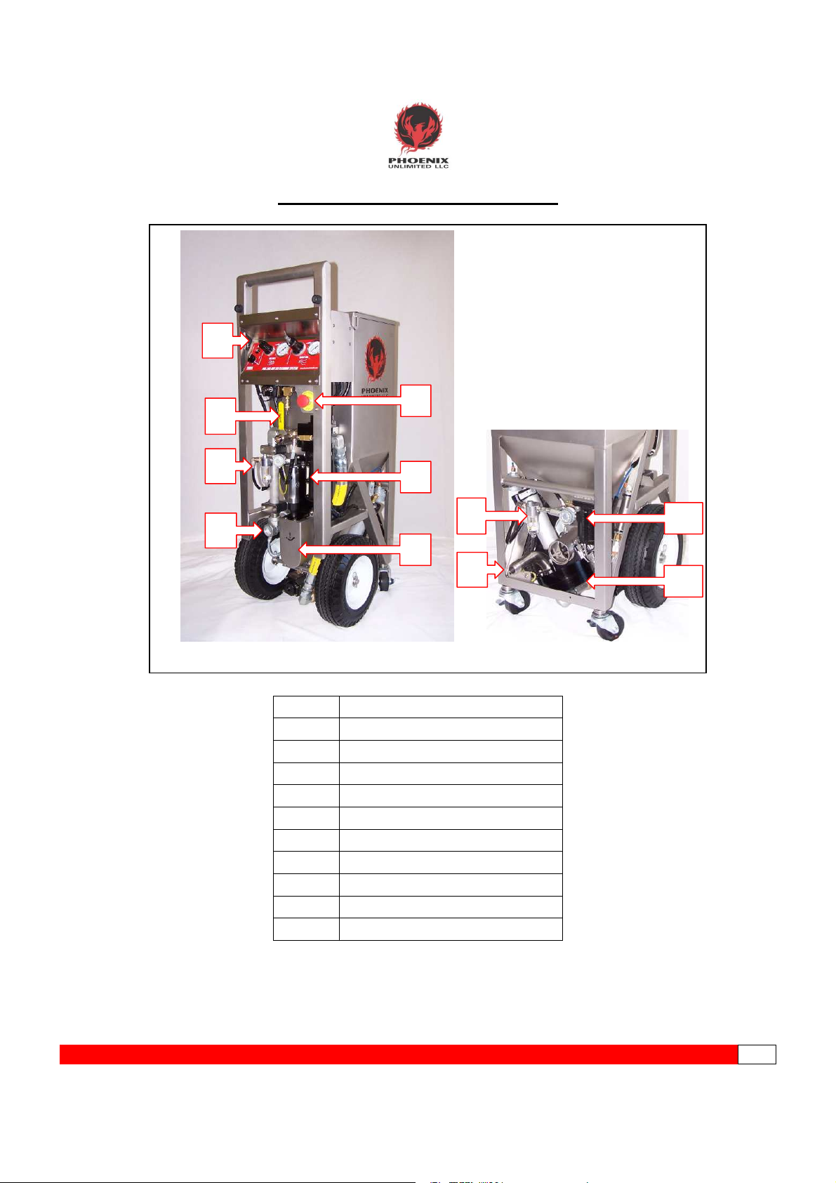
KEY COMPONENT IDENTIFICATION
1
2
5
3
6
8
4
10
7
9
11
1
2
3
4
5
6
7
8
9
10
11
Control Panel
System Supply Valve
Auger Drive Lubricator
Air Supply Inlet
E-Stop Button
Filter/Separator w/Autodrain
Auger Drive Assembly
Airlock Motor & Vibrator Lubricator
Blast Hose Connections
Vibrator Assembly
Airlock Assembly
PPHHOOEENNIIXXUUNNLLIIMMIITTEEDDLLLLCC--------------------------------------------PPHHXX--220000--------------------------------------------------------------UUSSEERRSSGGUUIIDDEEPPGG.
.8
Page 9
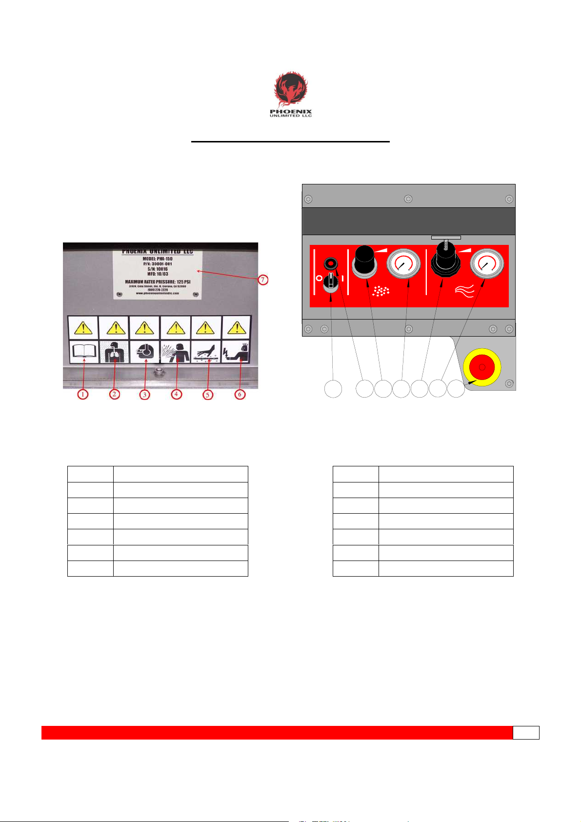
CONTROL PANEL/WARNING LABEL
1
Read User's Guide Information
2
Asphyxiation Hazard
3
Wear Proper Protective Gear
4
High Velocity Particles
5
Burn Hazard
6
Static Discharge
7
Equipment I.D. Tag
PHOENI X
UNLIM ITE D L LC
ARM
30
2
0
40
10
50
0
6
0
PSI
BLAST AIRICE RATE
PHX-200 DRY ICE C LEANING SYSTE M
2
1
3 4
1
ARM/DISARM Selector
2
ARM Indicator
3
ICE RATE Regulator
4
ICE RATE Gauge
5
BLAST AIR Regulator
6
BLAST AIR Gauge
7
EMERGENCY STOP Button
6
5
7
150
100
50
0
300
PSI
www.phoenixunlim itedllc.com
200
25
0
PPHHOOEENNIIXXUUNNLLIIMMIITTEEDDLLLLCC--------------------------------------------PPHHXX--220000--------------------------------------------------------------UUSSEERRSSGGUUIIDDEEPPGG.
.9
Page 10
OPERATING INSTRUCTIONS
This User’s Guide is the best tool available during the initialization of your new PHX-200 Dry Ice Cleaning
System. It contains all the information necessary for the proper installation, safety, operation,
maintenance and troubleshooting right at your fingertips. Familiarize yourself with its’ contents before
operating this equipment.
CONNECTING THE AIR SUPPLY
Since the PHX-200 is an “all pneumatic” design, it is critical that only clean, dry air be supplied to the unit.
Air containing excess amounts of moisture, oil, rust, or other contaminants may clog filters and damage
the logic control and internal components. A good desiccant or refrigerant dryer should be installed
between your compressor and the PHX-200. The dew point should not exceed +40°F/+4.4°C. Good air
quality will save you time for repairs and increase the life of the unit. The unit is supplied with a 1” female
NPT thread.
1. A 1” JIC male inlet fitting is recommended. Connect air supply hose to the PHX and extend the
whip check as far down the hose as possible. (pic 1,2,3)
2. Wearing hearing protection, blow down the air source at the drop to remove any accumulated
moisture. This helps to insure equipment performance. (pic 4)
3. Connect the air supply hose to the air source. (pic 5)
Caution! Maximum air pressure supplied to the PHX-200 should never exceed 250
PSI!
Pic 1 Pic 2 Pic 3
Pic 4 Pic 5
PPHHOOEENNIIXXUUNNLLIIMMIITTEEDDLLLLCC--------------------------------------------PPHHXX--220000--------------------------------------------------------------UUSSEERRSSGGUUIIDDEEPPGG.
.10
Page 11
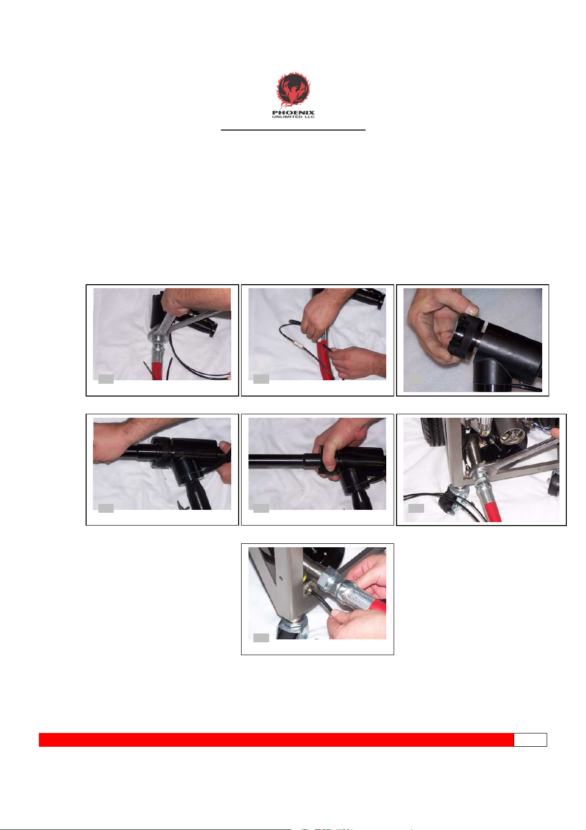
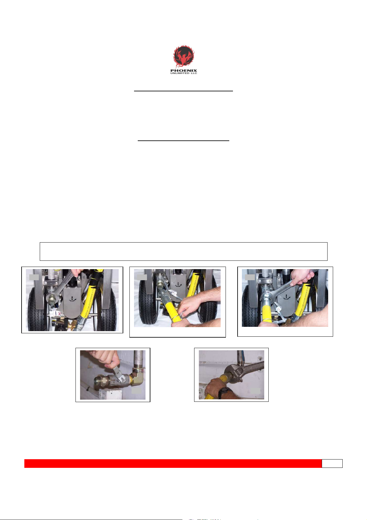
CONNECTING THE BLAST GUN
1. Use 1¼” and 1½” wrenches to connect the gun to the end of the blast hose with the shorter
length trigger lines. Do not over-tighten. (pic 1)
2. Connect the respective trigger lines (different sizes) to the gun, pushing firmly into the quick-
connect fittings. (pic 2)
3. Install the nozzle by a) twisting threaded retainer to completely ‘open’ position; b) place
nozzle into end of blast gun; c) tighten retainer to secure the nozzle. Improper seating of the
nozzle in the gun may result in air leakage. (pics 3, 4, 5)
4. Using the 1½” wrench, connect the remaining end of the blast hose to the front of the PHX-
200. (pic 6)
5. Connect the two trigger lines to the unit, pushing firmly until seated. Failure to attach trigger
lines will result in the non-functioning of the unit. (pic 7)
6. If necessary, ground the item you are blasting.
Pic 1 Pic 2 Pic 3
Pic 4 Pic 5 Pic 6
Pic 7
PPHHOOEENNIIXXUUNNLLIIMMIITTEEDDLLLLCC--------------------------------------------PPHHXX--220000--------------------------------------------------------------UUSSEERRSSGGUUIIDDEEPPGG.
.11
Page 12
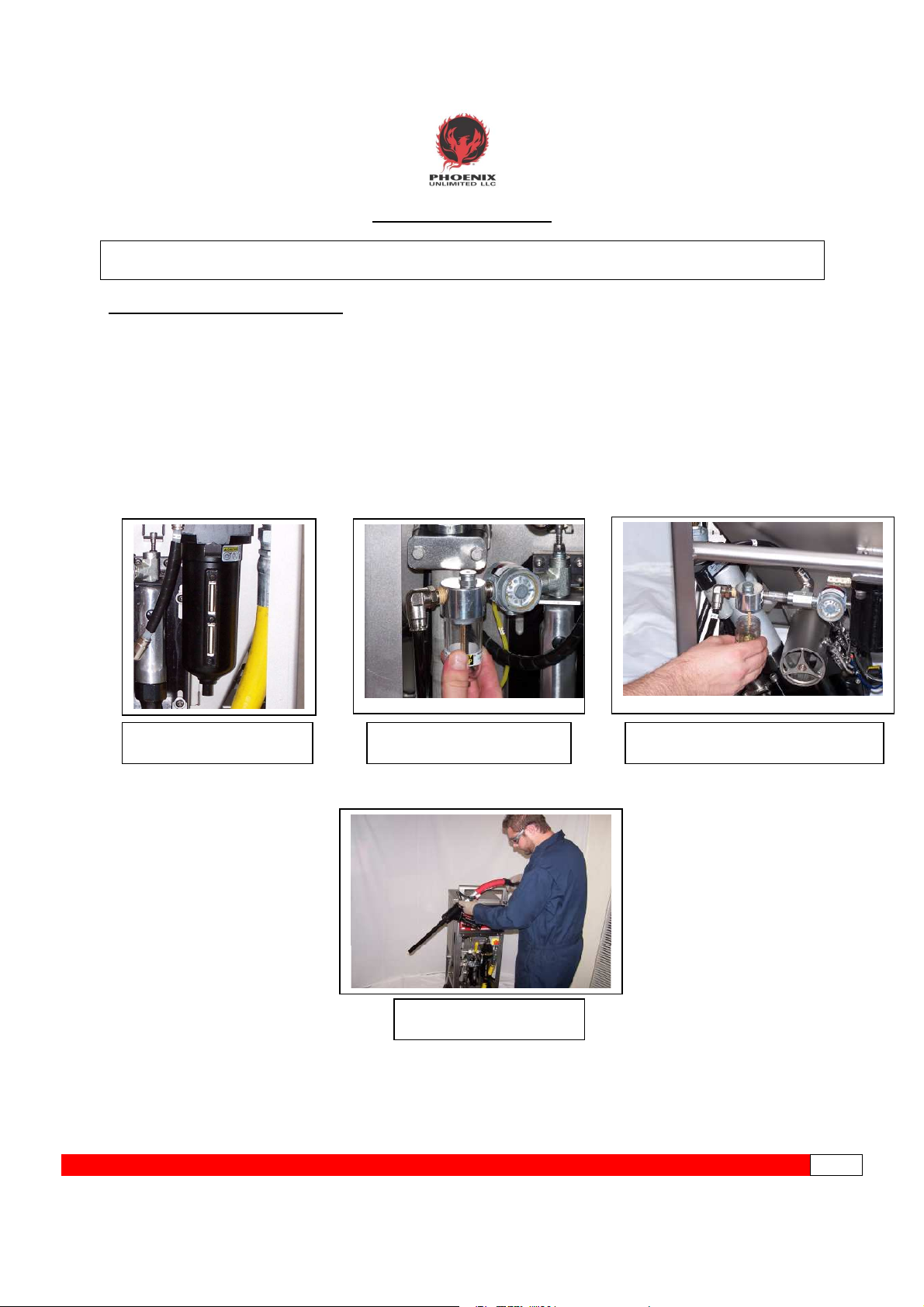
PRE-START UP CHECKS
CAUTION! Do not attempt to perform any maintenance or service on your PHX-200 unless safety
guidelines and lock out/tag out procedures have been satisfactorily met!
Before pressurizing the machine each day/shift, a quick preventive maintenance inspection should be
performed to ensure that your unit operates problem-free now and in the future.
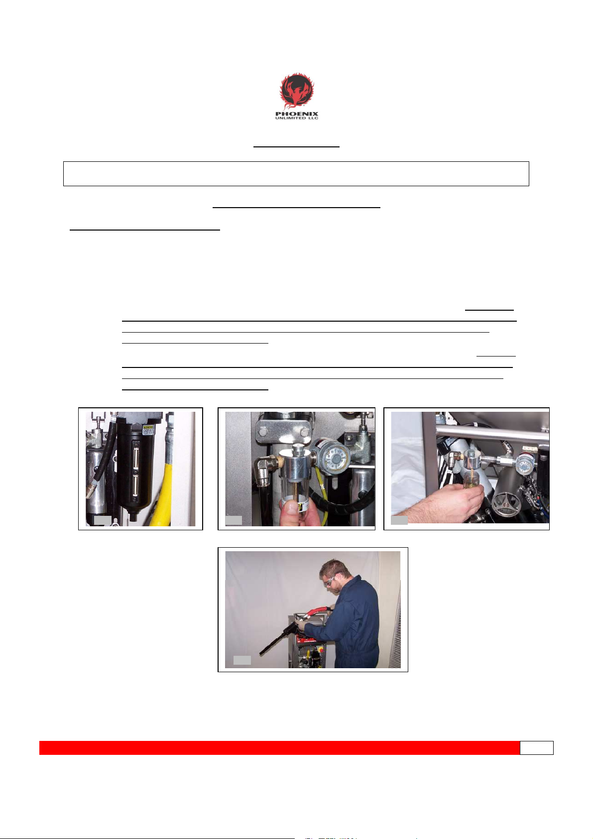
1. Check the Filter/Separator sight glasses for accumulated moisture or remove the canister to
inspect the filter for contamination. Clean canister and replace filter element if needed. A
COLLAPSED FILTER ELEMENT WILL CONTAMINATE THE SYSTEM. (pic 1)
2. Visually inspect lubricators to confirm fluid level is adequate. (pic 2 & 3) The bowls are
pressurized so be sure to close the System Supply Valve if removing bowl. (See page 19 for
detailed instructions on adding oil.)
3. Inspect hose assembly for cracks or leaks. Replace if necessary.
PIC 1
FILTER/REGULATOR
AUGER MOTOR LUBRICATOR
PIC 2
PIC 4
INSPECT BLAST HOSE
AUGER MOTOR LUBRICATOR
PIC 3
PPHHOOEENNIIXXUUNNLLIIMMIITTEEDDLLLLCC--------------------------------------------PPHHXX--220000--------------------------------------------------------------UUSSEERRSSGGUUIIDDEEPPGG.
.12
Page 13
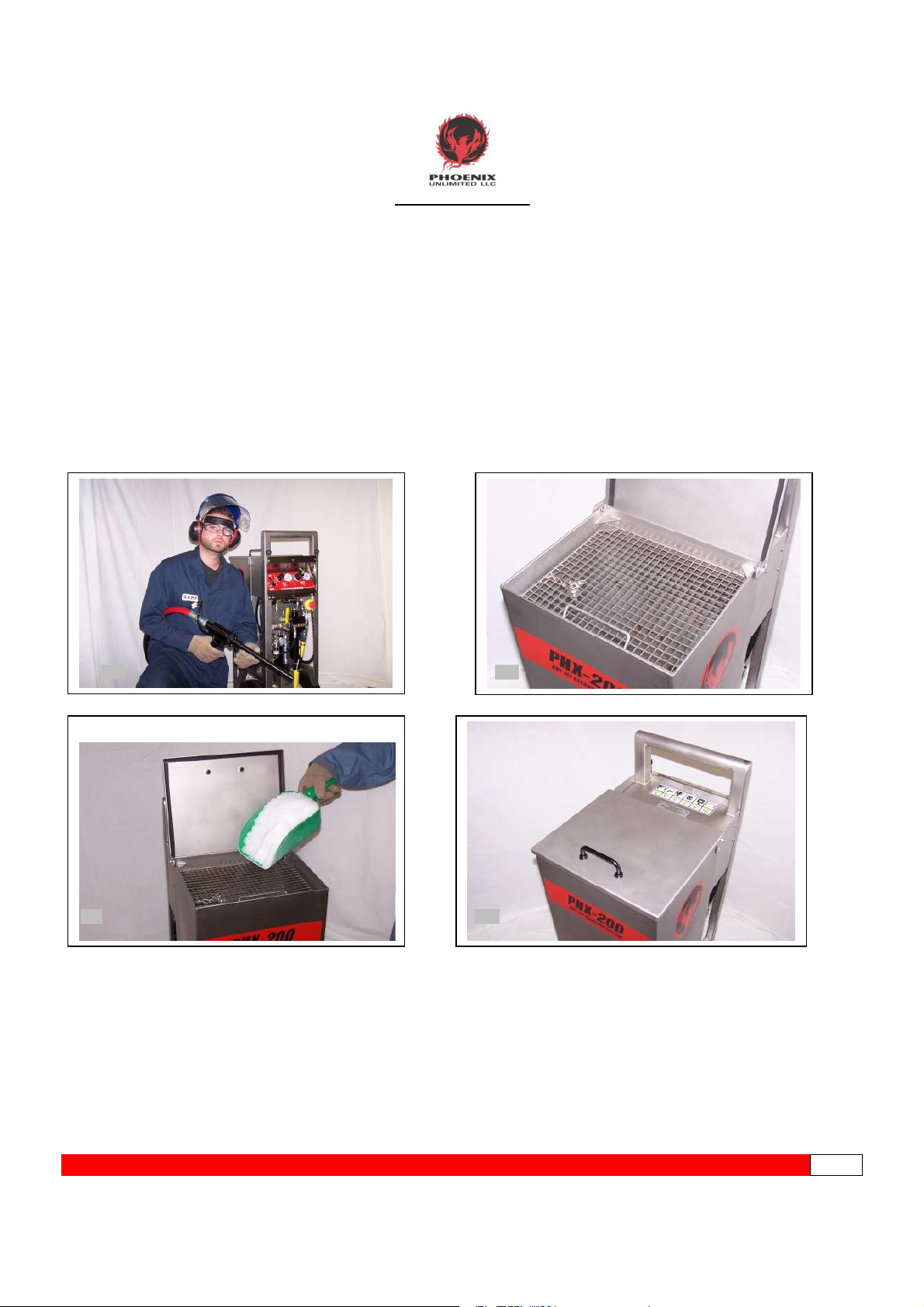
LOADING DRY ICE
1. Before you begin loading dry ice, it is important that you have the protective gear previously
mentioned in the “Safety Precautions and Warnings” section (page 6). This includes basic items
such as earplugs or muffs (or both), eye protection, face shield, heavy-duty gloves, long sleeves,
long pants, and safety shoes. (pic 1)
2. Lift hinged metal lid to expose hopper. BE AWARE OF AND KEEP CLEAR OF PINCH POINTS
(pic 2)
3. Use a sturdy scoop or similar device to load dry ice pellets into the hopper. (pic 3) Be careful not
to inhale concentrated CO2gas during the loading process, as it will temporarily rob you of
oxygen. If overexposed, get fresh air immediately. Signs of overexposure include dizziness, cold
sweats, headaches, nausea, and heavy breathing.
4. Close the lid on the hopper. This will prevent airborne contaminants from inadvertently falling
through the pellet screen to the ice and ultimately ending up on the surface you are cleaning or
damaging internal airlock parts. (pic 4)
Pic 1 Pic 2
Pic 4Pic3
PPHHOOEENNIIXXUUNNLLIIMMIITTEEDDLLLLCC--------------------------------------------PPHHXX--220000--------------------------------------------------------------UUSSEERRSSGGUUIIDDEEPPGG.
.13
Page 14
APPLYING AIR TO THE UNIT
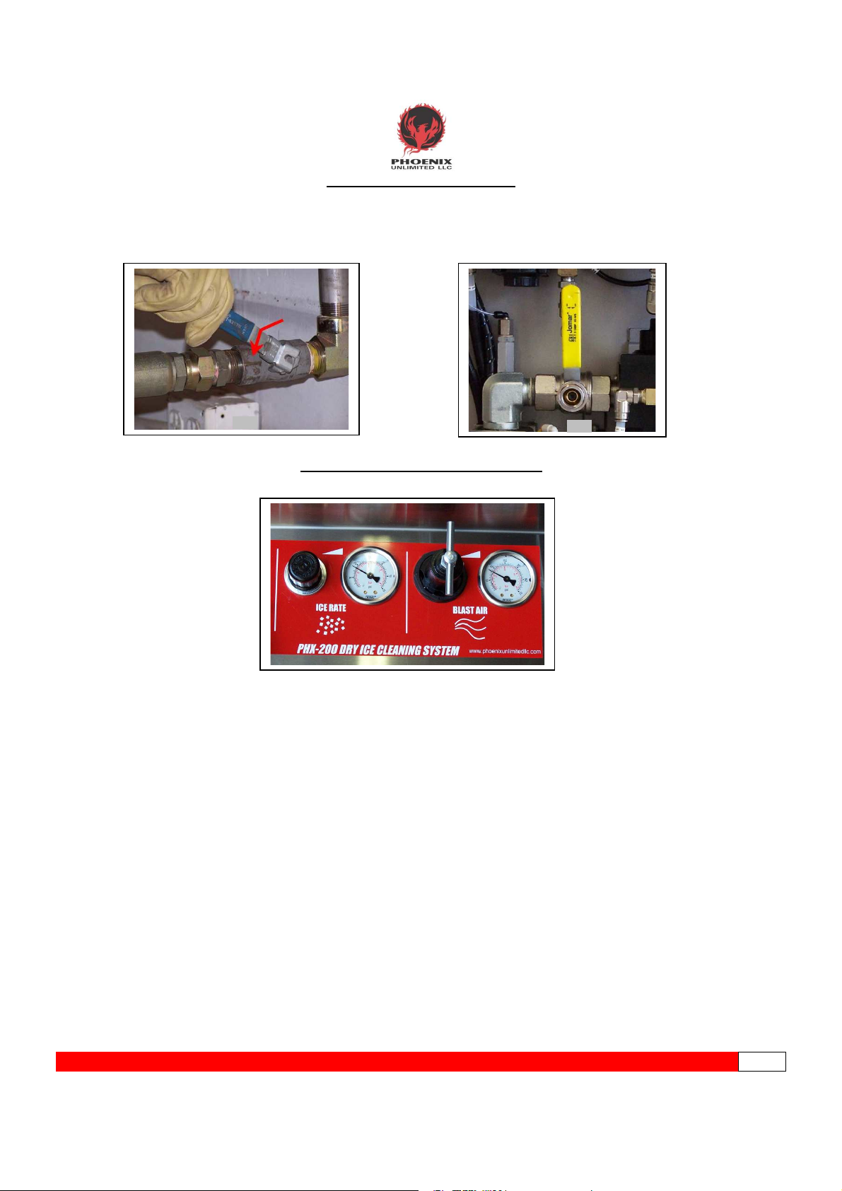
1. Slowly open the main air supply valve (source). (pic1)
2. With the gun secured and pointed in a safe direction, slowly open the system supply valve on the
PHX-200. To open pull outward on locking collar and turn handle to the left. (pic 2)
Pic 1
SETTING THE PANEL REGULATORS
(NOTE: The Panel Regulators may be adjusted at any time.)
ICE RATE CONTROLS
1. If locked, pull the ICE RATE knob outwards to unlock it.
2. Turn the knob clockwise to desired pressure. If unsure, start at about 25 PSI, then adjust the rate
up as necessary for your particular blasting application.
Note: It is normal for the pressure to drop 3-7 PSI (proportional to the set pressure)when
trigger is pulled, so adjust accordingly Experience will dictate proper settings.
Pic 2
3. Push the knob in to lock the ice rate.
BLAST AIR CONTROLS
1. Loosen jam nut on the tee handle to unlock it.(1/2” wrench)
2. Turn tee handle clockwise until desired pressure is reached. The PHX-200 has a blast pressure
range from 45-250 PSI. If you are unsure or are concerned about damage to the item being
blasted, start at a lower blast pressure and increase it gradually until the optimum performance
level is achieved.
3. Tighten jam nut to lock the blast air pressure.
Note: The PHX-200 is factory set to purge air and ice 3 seconds at 45 PSI after trigger is released
to clear the airlock and hose and prevent any clogging on the next trigger pull.
PPHHOOEENNIIXXUUNNLLIIMMIITTEEDDLLLLCC--------------------------------------------PPHHXX--220000--------------------------------------------------------------UUSSEERRSSGGUUIIDDEEPPGG.
.14
Page 15
ARMING/DISARMING THE PHX-200
The Arm/Disarm Selector is used to enable the gun trigger. It also enables the main control system.
Always Disarm when not blasting, especially when gun is unattended.
WARNING: If trigger is engaged when arming, the unit will start blasting immediately!
(NOTE: The PHX-200 will not arm if the E-STOP button is depressed, safety screen is removed, or
trigger supply line is disconnected.)
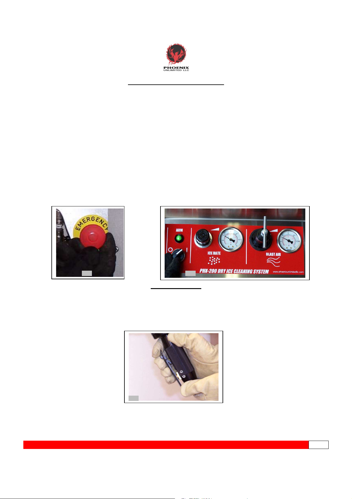
1. Check E-STOP button. The mushroom head has a push/pull operation. In the depressed position
the E-STOP button disables the arm system and the purge delay system. Pull out if required. (pic
1)
2. Again, be sure the gun is pointed in safe direction and secure. Turn the Arm/Disarm switch
clockwise to arm the PHX-200. The indicator will turn green, and the momentary switch will return
to the center position. The gun trigger is now live. Blast operations may now begin. (pic 2)
3. To Disarm, turn counterclockwise, trigger will be disarmed and indicator will turn red. (If blasting is
in process when Disarmed, the PHX-200 will enter its 3 second low pressure purge cycle then
stop. Blasting cannot be resumed until trigger is rearmed.)
Pic 1 Pic 2
READY TO BLAST
1. Be sure to be wearing proper protective gear at this point.
2. Hold the gun and nozzle handles securely. Aim the gun at the target or in a safe direction. Brace
yourself as there is a noticeable thrust when you pull the trigger. More reactive thrust will
experienced as blast pressure setting is increased.
3. Push upwards on the safety catch to release and pull the trigger to initialize blasting. (pic 3)
Pic 3
PPHHOOEENNIIXXUUNNLLIIMMIITTEEDDLLLLCC--------------------------------------------PPHHXX--220000--------------------------------------------------------------UUSSEERRSSGGUUIIDDEEPPGG.
.15
Page 16
STOP BLASTING
There are a few different ways to stop the blasting cycle. The PHX-200 reacts differently to each method.
They are as follows:
1. Normal Stop: (pic 1)
Under normal circumstances the way to stop blasting is to simply release the trigger. This will
stop the auger and blast air. The airlock and 45 psi purge air will continue for 3 seconds to
clear ice from hose then stop. Trigger remains armed and ready for more blasting. Pull trigger
again to resume.
2. Disarm Stop: (pic 2)
If someone besides the operator needs to stop the blasting operation they can turn the Arm
Selector counter-clockwise to Disarm the trigger. This will cause the indicator to turn red and
blasting will stop and end with 3 sec. 45 psi purge cycle (as if trigger was released.) Trigger
will need to be armed again before blasting. Be sure trigger has been released and gun is secure
before re-arming the trigger. (NOTE: If trigger is engaged when arming, the unit will start blasting
immediately. )
3. EMERGENCY STOP: (pic 3)
In case of an emergency push the red mushroom head EMERGENCY STOP button. This will
stop all functions instantly and disarm the trigger. Button will remain depressed. To reset pull
button back out. Trigger will need to be armed before blasting.
4. System Supply Stop: (pic 4)
Closing System Supply Valve will stop all airflow, disarm and vent the control system.
Pic 1 Pic 2
Pic 4
Pic 3
PPHHOOEENNIIXXUUNNLLIIMMIITTEEDDLLLLCC--------------------------------------------PPHHXX--220000--------------------------------------------------------------UUSSEERRSSGGUUIIDDEEPPGG.
.16
Page 17

SHUT DOWN
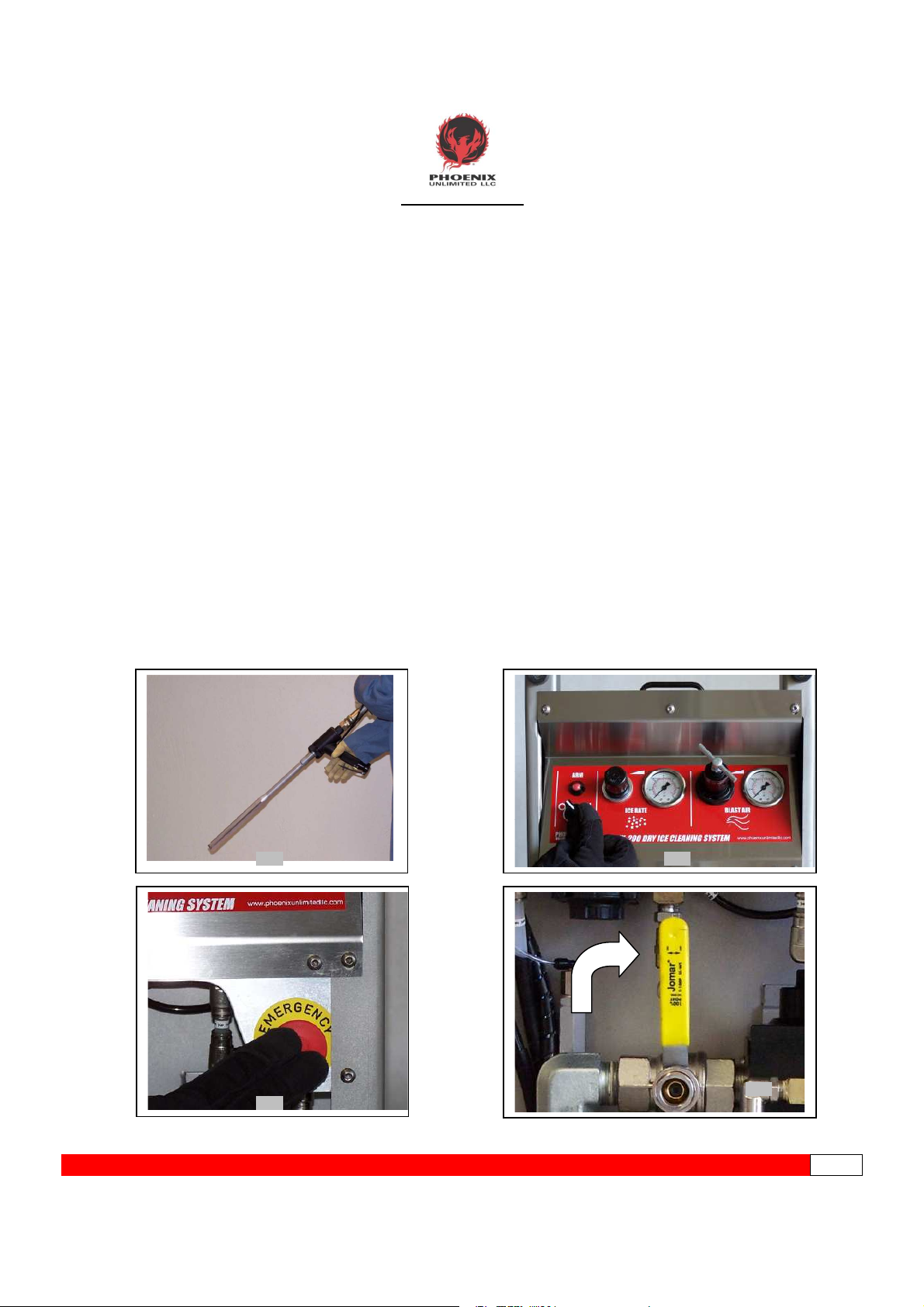
1. When blasting is complete, release the trigger and wait for airflow to stop. (There is a short
delay while residual ice is purged at 45 PSI from the blast hose. Keep gun pointed at the
target until air stops flowing! (Pic 1)
2. Turn the Arm/Disarm switch counter-clockwise. The indicator will turn red, and the
momentary switch will return to the center position. E-Stop button may be depressed if
desired. System will not Arm if the E-stop button is depressed. (Pic 2)
3. Close System Supply Valve. Lockout collar will latch and system will vent. (Pic 3) System
may be locked out with a padlock through the lockout collar.
4. Close the air supply valve at the source. (Pic 4)
5. Vent remaining air from the machine and supply hose by opening the System Supply Valve
approximately halfway. After the air stops flowing, you may fully close the valve. Lock Out
valve if required. (Pic 5)
6. If moving the unit to another location for blasting, disconnect the supply hose from the unit.
Wrap the blast hose with gun connected carefully around the machine handle for quick
transport. Use extra caution when moving unit while hoses are connected. For extended shut
down remove ice from hopper and disconnect blast hose. Roll up hoses and store in a safe
location. (Pic 6)
Pic 1 Pic 2 Pic 3
Pic 4 Pic 5
Pic 6
PPHHOOEENNIIXXUUNNLLIIMMIITTEEDDLLLLCC--------------------------------------------PPHHXX--220000--------------------------------------------------------------UUSSEERRSSGGUUIIDDEEPPGG.
.17
Page 18
MAINTENANCE
CAUTION! Do not attempt to perform any maintenance or service on your PHX-200 unless safety
guidelines and lock out/tag out procedures have been satisfactorily met!
DAILY PREVENTIVE MAINTENANCE
Before pressurizing the machine each day/shift, a quick preventive maintenance inspection should be
performed to ensure that your unit operates problem-free now and in the future.
1. Check the Filter/Separator sight glass for accumulated moisture or remove the canister to
inspect the filter for contamination. Clean canister if needed. A COLLAPSED FILTER
ELEMENT WILL CONTAMINATE THE SYSTEM (See page 20 for canister removal and filter
replacement procedure). (pic 1)
2. Visually inspect Auger Drive Lubricator to confirm fluid level is adequate. (pic 2) The bowl is
pressurized so be sure to close the System Supply Valve if removing bowl. (See page 19 for
detailed instructions on adding oil.) OPERATING WITHOUT OIL WILL DAMAGE THE
MOTOR AND VOID WARRANTY.
3. Visually inspect Airlock/Vibrator Lubricator to confirm fluid level is adequate. (pic 3)The bowl
is pressurized so be sure to close the System Supply Valve if removing bowl. (See page 19
for detailed instructions on adding oil.) OPERATING WITHOUT OIL WILL DAMAGE THE
MOTOR AND VOID WARRANTY.
4. Inspect hose assembly for cracks or leaks. Replace if necessary. (pic 4)
Pic 1 Pic 2 Pic 3
Pic 4
PPHHOOEENNIIXXUUNNLLIIMMIITTEEDDLLLLCC--------------------------------------------PPHHXX--220000--------------------------------------------------------------UUSSEERRSSGGUUIIDDEEPPGG.
.18
Page 19

ADDING OIL
CAUTION! Do not attempt to perform any maintenance or service on your PHX-200 unless safety
guidelines and lock out/tag out procedures have been satisfactorily met!
There are two lubricators on the PHX-200. One is for the Auger Motor located below the control panel,
and the other is for the Airlock Motor and Hopper Vibrator located on the opposite side of the machine
above the Blast Hose Connection.
AUGER DRIVE LUBRICATOR AIRLOCK & VIBRATOR LUBRICATOR .
Visually inspect oil levels daily and add oil before lubricator bowls are empty. If wet dirty air is being used,
water, dirt, rust and emulsified oil can accumulate in lubricator bowls, making it look like they are full of oil.
A periodic “closer look” is recommended and an oil change is recommended if it is contaminated with
water. To add oil follow these steps.
1. Close System Supply Valve and wait a few seconds before attempting to add oil. (Pic 1)
2. Grasp bowl, unscrew bowl from lubricator body. Be sure to locate the O-ring. (Pic 2)
3. Add 10W tool oil until level with max fill line. Be sure that the O-ring is properly seated in the
top of the lubricator bowl. Reinstall the bowl. (Pic 3)
Pic 1 Pic 2 Pic3
4. Oil may be added by removing top plug on lubricator and adding oil there. (Pic 4)
Pic 4
PPHHOOEENNIIXXUUNNLLIIMMIITTEEDDLLLLCC--------------------------------------------PPHHXX--220000--------------------------------------------------------------UUSSEERRSSGGUUIIDDEEPPGG.
.19
Page 20

MAIN FILTER/SEPARATOR INSPECTION AND REPLACEMENT
CAUTION! Do not attempt to perform any maintenance or service on your PHX-200 unless safety
guidelines and lock out/tag out procedures have been satisfactorily met!
To ensure that your dry ice cleaning system operates correctly and continues to provide reliable
performance levels, the separator needs to be inspected regularly. Poor filtering leads to excessive
moisture being passed into the control system, airlock, blast gun, and ultimately to the targeted surface. A
discolored filter element should be replaced. A plugged element will collapse allowing dirt and
contamination to pass and cause damage to the system.
To gain access to the filter element, follow this simple procedure:
1. Close System Supply Valve to isolate Filter/Separator. Lockout collar will latch and system
will vent. Lock Out with padlock if required. (Pic 1)
2. Press locking tab on separator canister and turn in either direction to disengage. (Pic 2)
3. Lower the canister straight down to clear filter element. (Pic 3)
4. Remove baffle by turning counter-clockwise. (Pic 4)
5. Filter element should come off with baffle. If not, pull gently downward on element. (Pic 5)
6. Inspect filter element and deflector. (Pic 6) Install new element by reversing steps.
To avoid damage to the stem, be very careful when removing the bowl, baffle and element to
completely clear the stem before pulling out element. Undo pressure on the stem can cause
damage to regulator requiring stem replacement.
Pic 1 Pic 2 Pic3
Pic 4 Pic 5 Pic 6
FOR MORE FILTER/SEPARATOR/REGULATOR DETAILS SEE PAGE 42
PPHHOOEENNIIXXUUNNLLIIMMIITTEEDDLLLLCC--------------------------------------------PPHHXX--220000--------------------------------------------------------------UUSSEERRSSGGUUIIDDEEPPGG.
.20
Page 21

TRIGGER LINE AND BLAST AIR PILOT FILTERS
If the unit is ready to blast (Arm/Disarm indicator is green), but does not start or only partially starts when
the trigger is pulled, it may indicate the need to change the Trigger Line Filter element.
To perform this:
1. Locate the filter housing on inner leg of the PHX-200 near the airlock motor. (pic1)
2. Disconnect the tubing from filter housing push fittings (both ends), then remove filter housing from
unit. (pic 2)
3. Using two ¾” wrenches, remove the cap from the filter housing to expose the sintered bronze
filter element. (pic 3)
4. Remove filter element. Important: Remember proper configuration of internal spring in
relation to the element. Improper installation will result in the non-operation of the unit.
(pic 4)
5. Install new filter element and housing by reversing steps 2-4.
Pic 1 Pic 2
Pic 3 Pic 4
There is also another identical element for the blast air pilot filter. It is located on the air system.
TO REPLACE THIS ELEMENT THE SYSTEM MUST BE DISCONNECTED FROM THE AIR SOURCE
AS IT IS PRESSURIZED EVEN WHEN THE SYSTEM SUPPLY VALVE IS CLOSED.
Replacement is the same but do not remove housing from system. Just remove tube and separate as
shown in pic 3 and 4.
PPHHOOEENNIIXXUUNNLLIIMMIITTEEDDLLLLCC--------------------------------------------PPHHXX--220000--------------------------------------------------------------UUSSEERRSSGGUUIIDDEEPPGG.
.21
Page 22

PERIODIC MAINTENANCE
CAUTION! Do not attempt to perform any maintenance or service on your PHX-200 unless safety
guidelines and lock out/tag out procedures have been satisfactorily met!
AUGER DRIVE CHAIN
Over time, the stainless steel drive chain may stretch; it is recommended that the drive chain
tension be checked after every few months. A loose chain can skip or bind and can cause damage to the
stainless steel sprockets. Also a chain that is too elongated will not mesh properly with the sprockets and
should be replaced. A chain that is over tightened may stretch and cause premature chain failure and
sprocket wear.
Checking / Adjusting the Drive Chain Tension
1. Use a 5/32” hex key wrench to loosen two screws located at the top of the motor/chain guard.
Do not remove the screws. (pic 1)
2. Gently tilt the unit forward and remove third screw located at the bottom of the guard. (pic 2)
3. Remove the chain guard to reveal drive chain. (pic 3)
4. Apply pressure to mid-span point. Movement should not be more than 3/32”. (pic 4)
5. If tension adjustment is necessary, loosen the two upper hex screws on the motor mounting
plate.(pic 5)
6. Locate the drive chain adjustment screw at the very top of the motor mounting plate. (pic 6)
Pic 1
Pic 2 Pic 3
Pic 6
Pic 4 Pic 5
PPHHOOEENNIIXXUUNNLLIIMMIITTEEDDLLLLCC--------------------------------------------PPHHXX--220000--------------------------------------------------------------UUSSEERRSSGGUUIIDDEEPPGG.
.22
Page 23

Checking / Adjusting the Drive Chain Tension (cont.)
1. Use a 7/16” box wrench to loosen the adjustment screw retaining nut by turning counter-
clockwise. (pic 7)
2. Hold the retaining nut in position and use a 3/16” hex key wrench to adjust the screw
(clockwise to increase tension, counter-clockwise to relieve) until proper tension is achieved.
(pic 8)
3. Tighten the retaining nut to lock the adjustment screw into place. (pic 9)
4. Tighten the two upper hex screws on the motor mounting plate. (pic 10)
5. Verify that the auger directional switch on motor ratchet is rotated fully clockwise. (pic 11)
6. Install the chain guard and tighten the three screws that secure the guard into place (pic 12)
Pic 7 Pic 8 Pic 9
Pic 10
Pic 11 Pic 12
VIBRATOR
The Vibrator Pad (30031-001) will wear over time allowing the piston to strike the bare frame
metal. The Pad can be replaced by removing the four mounting bolts.
The Vibrator can be service by removing it from the frame. Remove the two screws that secure
the end cap. Use caution not to tear the gasket and remove end cap. Remove piston and clean any
debris and rust from bore and piston using ATF fluid. Reassemble piston and end cap. Piston should
move freely. Reinstall unit to frame.
PPHHOOEENNIIXXUUNNLLIIMMIITTEEDDLLLLCC--------------------------------------------PPHHXX--220000--------------------------------------------------------------UUSSEERRSSGGUUIIDDEEPPGG.
.23
Page 24

AIRLOCK
Replacing Airlock Critical Components
Diminished performance or a noticeable drop in blast pressure at the gun may indicate a worn or
damaged component in the airlock. Most airlock problems are typically caused by a foreign object
(airborne or otherwise) falling through the hopper pellet screen, mixing with the dry ice pellets, and
becoming lodged inside the airlock or doing damage as it passes through to the blast hose and gun.
(Note: You can avoid unnecessary expense and repairs by closing the hopper lid after filling with
ice and prior to blasting.) In order to properly inspect or replace the critical components, the airlock
assembly must be removed from the unit. To do this:
1. Remove air supply hose from the PHX-200. Also remove the gun and blast hose assembly if
attached. (pic 1)
2. To avoid spillage, remove the lubricator bowls and set aside. (pic 2)
3. Detach the inlet blast air hose coupling from airlock assembly inlet. (pic 3).
4. Carefully place some blocks on the ground. Lay the unit on the blocks with the control panel
facing down using care to prevent the regulator and e-stop button from being damaged. Be
careful that hinged metal lid does not “flop” backwards suddenly during this procedure. (pic 4)
5. Remove the airlock motor air supply lines from the push fittings. (pic 5)
6. Remove the large cotter pin from the airlock retaining latches. (pic 6)
Pic 1 Pic 2
Pic 4 Pic 5 Pic 6
Pic 3
PPHHOOEENNIIXXUUNNLLIIMMIITTEEDDLLLLCC--------------------------------------------PPHHXX--220000--------------------------------------------------------------UUSSEERRSSGGUUIIDDEEPPGG.
.24
Page 25

Replacing Airlock Critical Components (cont.)
7. Open airlock retaining latches. (pic 7)
8. Remove complete airlock assembly from unit and move it to a workbench. (pic 8)
9. Use a 3/16” hex key wrench to remove six housing bolts from bottom of airlock assembly. (pic 9)
10. Separate the housing and set bottom half aside. (pic 10)
Pic 7 Pic 8 Pic 9 Pic 10
Rotor:
11. Carefully remove the rotor from the spline and
inspect. Replace if damaged. Before installation
of new rotor, clean and inspect the pads, motor,
spline and internal walls of the housing for
damage. If all parts are good, install the new
rotor onto the spline. (pic 11)
12. Reinstall airlock assembly onto the PHX-200 by
reversing steps 1-10.
Pic 11
Airlock Motor / Spline:
13. While the housing is disassembled, inspect the motor and spline. If replacement is necessary, the
motor will need to be removed from the housing. (pic 12)
14. Use a ¼” hex key wrench to remove the two mounting screws, then remove the motor assembly.
(pic 13)
15. Use two wrenches to remove the spline from the motor and install new one. (pic 14)
16. Be sure centering ring is in place and reinstall motor.
17. Reinstall airlock assembly by reversing steps 1-11.
REINSTALL
AIRLOCK
ASSY. BY
REVERSING
STEPS 1-10
REINSTALL
AIRLOCK
ASSY. BY
REVERSING
Pic 12 Pic 13 Pic 14
STEPS 1-11
PPHHOOEENNIIXXUUNNLLIIMMIITTEEDDLLLLCC--------------------------------------------PPHHXX--220000--------------------------------------------------------------UUSSEERRSSGGUUIIDDEEPPGG.
.25
Page 26

AIRLOCK MOTOR (P/N 50202-001) MAINTENANCE
Engine Lubrication- Be sure air lubricators are maintained as outlined in equipment
manual. If wet dirty air is being used, water, dirt, rust and emulsified oil can accumulate
in lubricator bowls, making it look like they are full of oil. A periodic “closer look” is
recommended and an oil change is recommended if it is contaminated with water.
Cleaning Engine- Water and rust in the compressed air or dust and wear particles can
cause sticking of vanes, valves etc. This can be prevented by removing muffler, flushing
with a few drops of oil, running the motor for 5-10 seconds and absorbing the oil in a
cloth. Replace or reinstall muffler. Protect the engine this way before long shutdown
periods. DO NOT RUN THE AIRLOCK FOR LONG PERIODS WITHOUT ICE.
Muffler-Over time the muffler can become clogged with particles and restrict exhaust
flow which will make the motor run slower. It is recommended to periodically replace the
muffler. (P/N 50203-001)
Maintenance and repairs must be carried out exclusively by authorized personnel.
Overhaul- To achieve the best service life under normal operating conditions, regular
overhaul and cleaning should be carried out every 12 months or 2000 hrs., whichever is
sooner. Overhaul should be carried out more frequently under more rigorous operating
conditions.
Lubrication- Planetary gears, ball and needle bearings and seal ring should be
lubricated with grease in conjunction with the regular overhaul of the motor. Molykote
BR2 Plus gives long intervals between lubrications.
Contact Phoenix Unlimited LLC or a qualified service center for motor overhaul options
PPHHOOEENNIIXXUUNNLLIIMMIITTEEDDLLLLCC--------------------------------------------PPHHXX--220000--------------------------------------------------------------UUSSEERRSSGGUUIIDDEEPPGG.
.26
Page 27

5
4
6
7
9
8
1. 50202-001 MOTOR
2. 30281-001 SPLINED SHAFT
3. 30278-001 CENTERING RING
4. 50203-001 MUFFLER
5. 50114-688 ELBOW
6. 50114-158 ELBOW
7. 50004-002 ELBOW
8. 50053-001 VALVE
9. 50015-002 CONNECTOR
10. 50002-F04 PLUG
11. 50057-628 ELBOW
10
11
FOLLOWING ITEMS NOT SHOWN
12. 10020-P12 BOLT (2)
1
2
13. 10018-005 LOCKWASHER (2)
3
PHOENIX UNLIMITED LLC
30275-002A
AIRLOCK MOTOR ASSEMBLY
COMPLETE
PPHHOOEENNIIXXUUNNLLIIMMIITTEEDDLLLLCC--------------------------------------------PPHHXX--220000--------------------------------------------------------------UUSSEERRSSGGUUIIDDEEPPGG.
.27
Page 28

FACTORY SETTINGS
There are two factory set and locked regulators on the PHX. They are not readily accessible, so
the chance of someone randomly changing their settings is low. However, if problems arise they should
be checked. Many problems can stem from these regulators being out of adjustment.
There is also a speed control valve that controls the duration of the purge delay. This allows the
Airlock Motor and the purge air pressure to continue running for a time period to clear the airlock and
hose of ice.
Purge Delay Speed Controller
The factory setting of this delay is 3 seconds. This time period can be easily adjusted, as the Speed Controller is
readily accessible, located under the Control Shelf.
To adjust:
1. Locate Speed Controller knob, loosen knurled jam nut.
2. Adjust knob. Turn valve in to increase delay or back valve out to shorten the delay.
3. Cycle the trigger on and off. Repeat until purge cycle stops 3 seconds after trigger is released. To lock
setting, tighten the jam nut. WARNING: If valve is closed completely, the purge cycle will not disengage.
Control Air Regulator
This regulator protects the entire control system and the Auger Ratchet Motor. This setting is critical as the
system needs 70-80 PSI to operate properly, and settings over 90 PSI can damage control system components.
Although there is a 90-PSI relief valve, do not set blindly, Use gauge to check and set.
To check:
1.Close System Supply Valve
2.Remove small black tube from front of regulator and connect a pressure gauge to the fitting where tube was
removed.
3.Open System Supply Valve
4.Gauge should read 80 PSI.
To Set:
1. Set up gauge and check pressure as described above.
2. Remove Left Side Cover to access Control Air Regulator.
1. Locate locknut on the T-Handle adjustment screw. Loosen locknut with 9/16” wrench. Use care working
around the small tubing not to snag it on the wrench or T-Handle.
2. To Set: First back off regulator pressure by turning T-handle counter/clockwise, and then raise the
regulator by slowly turning T-Handle clockwise until 80-PSI is reached.
3. Lock in setting by tightening locknut.
4. Close System Supply Valve and reconnect small black tube.
5. Check operation of unit and replace side cover.
PPHHOOEENNIIXXUUNNLLIIMMIITTEEDDLLLLCC--------------------------------------------PPHHXX--220000--------------------------------------------------------------UUSSEERRSSGGUUIIDDEEPPGG.
.28
Page 29

FACTORY SETTINGS (continued)
Airlock Speed/Vibrator Stength/Purge Pilot Regulator
This regulator controls the RPM of the Airlock Motor, the vibrating force of the vibrator and the Purge Air Pilot
pressure to the Filter/Regulator. This setting is critical as these systems are balanced to run off the same
pressure setting.
To check:
1.Close System Supply Valve
2.Remove large black tube from regulator and connect a pressure gauge to the fitting where tube was
removed.
3.Open System Supply Valve
4.Gauge should read 45 PSI.
To Set
1. Attach gauge and check pressure as described above.
2 Remove Right Side Cover to access Regulator.
6. Locate Regulator knob. Pull up on the knob to unlock.. Use care working around the small tubing
4. Back off regulator pressure, then raise the regulator by slowly turning handle until 45-PSI is reached.
5. Lock in setting by pushing down on knob.
6. Close System Supply Valve and reconnect large black tube.
7. Check operation of unit and replace side cover.
PPHHOOEENNIIXXUUNNLLIIMMIITTEEDDLLLLCC--------------------------------------------PPHHXX--220000--------------------------------------------------------------UUSSEERRSSGGUUIIDDEEPPGG.
.29
Page 30

PPHHOOEENNIIXXUUNNLLIIMMIITTEEDDLLLLCC--------------------------------------------PPHHXX--220000--------------------------------------------------------------UUSSEERRSSGGUUIIDDEEPPGG.
.30
Page 31

PPHHOOEENNIIXXUUNNLLIIMMIITTEEDDLLLLCC--------------------------------------------PPHHXX--220000--------------------------------------------------------------UUSSEERRSSGGUUIIDDEEPPGG.
.31
Page 32

TROUBLESHOOTING
SYSTEM
COLOR
SIZE
DUTIES
DISTRIBUTION
BLAST CYCLE CONTROL
PURGE DELAY CONTROL
Before attempting to troubleshoot, be sure all pre-set factory pressure settings are correct. Problems can
stem from these regulators being out of adjustment. to be sure to rule these settings out, they should be checked
first thing. SEE “FACTORY SETTINGS”.
Contaminated air is the cause of most problems that may occur in pneumatic systems. There are Filters that if
maintained properly will perform exceptionally well. However excessive moisture and contamination combined
with lack of maintenance will clog the filters, and if not replaced will finally collapse and allow all the dirt, rust and
crud to enter the system. The best way to avoid problems is to know the air you are using and maintain filters
accordingly. For fewer filter changes take steps to provide clean dry air to the PHX.
The use of the Model 200 Schematic and the Tubing Diagrams are extremely helpful when troubleshooting
the PHX. Have this guide handy if calling Phoenix Unlimited for technical support. Also, assembly drawings are
included in the back of this guide.
The PHX-200 can be function tested for short periods with a standard ¼” shop air hose. Do not run airlock dry
for extended periods. You will need the following items to set it up. Fittings to connect shop air hose to the 1” inlet
on the PHX-200. 1” JIC Cap to cap off blast hose connection. Cap off Airlock outlet at the blast hose connection.
Connect air to the machine. Operate trigger as usual. To operate for longer times, remove and cap off Blue pilot
tube from the Airlock Control Valve, this will prevent the airlock from running dry for too long while you diagnose.
A Note on Tubing Color and Control Systems
When troubleshooting, it is essential to understand the 6 control and distribution systems in the PHX. Each
system is identified by its control tubing size and color. This information will help point you in the right direction.
The systems and respective tubing are as follows:
HIGH PRESSURE
DISTRIBUTION
BLAST AIR PRESSURE
CONTROL
CONTROL AIR
ARM/DISARM CONTROL RED 5/32 Arms disarms Trigger, enables Blast Control System (yellow)
VIBRATOR CONTROL CLEAR 5/32 Controls timing of vibrations
WHITE 3/8 Supplies full pressure filtered air to System Control Regulator and
Airlock/Vibrator/Purge Regulator.
CLEAR 1/8 Controls pilot pressure applied to the blast air regulator
BLACK 5/32 Supplies regulated air to control systems
YELLOW 5/32 Energizes Auger, Blast Air Pilot Valve,
enables Vibrator Control System (Clear) Purge Delay System (blue)
BLUE 5/32 Energizes airlock motor, air control valve, and blast air ball valve,
this system stays energized for about 3 seconds after trigger is
released
PPHHOOEENNIIXXUUNNLLIIMMIITTEEDDLLLLCC--------------------------------------------PPHHXX--220000--------------------------------------------------------------UUSSEERRSSGGUUIIDDEEPPGG.
.32
Page 33

TROUBLESHOOTING TABLES
SYMPTOM
ITEM CHECK
CORRECTIVE MEASURE
Trigger Return Filter F3 plugged
Check filter and replace element if necessary.
PHX-200 WILL
NOT ARM
TRIGGER DOES
NOT START BLAST
CYCLE
System Supply Valve V1
not open
E-STOP Button is depressed Pull E-STOP Button out to enable ARM System
Safety Screen is not properly
installed
Trigger lines improperly
connected
Inspect entire length of Large
Trigger Line for holes or cuts
Loose or kinked tubing in
Control Panel
Control Air Pressure has
changed from factory setting
of 80 PSI
System contamination,
Main filter collapsed due to
improper maintenance causing
control and logic valve
malfunctions.
PHX-200 not ARMED
(indicator red)
Trigger Lines improperly
connected
Open System Supply Valve {yellow handle)
Make sure Safety Screen fully engages interlock
valve V2 when installed
Check trigger lines at the machine and at the gun.
Replace or repair Trigger Line as required.
Check for loose or kinked tubing behind
Control Panel and E-STOP button, especially
the Red tubes. All Red tubing is directly related
to the ARM system.
Tee into the Control Air Pressure outlet to check
pressure. SEE “FACTORY SETTINGS”
Adjust to set at 80 PSI.
Check main filter as outlined. If filter has
collapsed, use schematic and tube diagrams
to trace back through tubing, valve bodies (VB-2,
VB-3, VB-4) logic elements (L-4 L-5) to find where
system is plugged or which device is malfunctioning.
Clean out or replace tubing or device.
Correct cause of contamination.
Turn ARM selector clockwise,
(indicator should turn green)
Check trigger lines at the machine and at the gun.
Trigger Line contamination Blow out trigger lines, correct cause of contamination
Trigger Valve failure Check trigger valve for contamination, clean or
replace as necessary. Correct cause of
contamination.
Malfunctioning logic element. Check operation of L3, replace if necessary.
TRIGGER STARTS
BLAST AIR BUT NO
ICE COMES OUT OF
GUN
System contamination,
Main filter collapsed due to
improper maintenance causing
control malfunction.
There are no dry ice pellets in
the hopper
Ice Rate set to low Turn Ice Rate Regulator clockwise to increase.
Ice bridging in hopper With Pellet Screen in place use poker to break up the
Water ice accumulation in
hopper.
Check main filter as outlined. If filter has
collapsed use schematic and tube diagrams to
trace back through tubing, logic element (L-3)
to find where system is plugged or which device
is malfunctioning. Clean out or replace tubing or
device. Correct cause of contamination.
Load fresh ice into hopper
bridge. This symptom is usually caused by poor ice
quality and high humidity areas.
Water ice forms in high humidity areas and when
ice is left idle in hopper for long periods of time.
Clean and dry hopper thoroughly before refilling.
PPHHOOEENNIIXXUUNNLLIIMMIITTEEDDLLLLCC--------------------------------------------PPHHXX--220000--------------------------------------------------------------UUSSEERRSSGGUUIIDDEEPPGG.
.33
Page 34

BLAST GUN PLUGS
Ice Rate set too low
Increase Ice Rate pressure.
REPEATEDLY
AUGER DOES NOT
TURN
Discharge outlet, Blast Hose
or Gun plugged.
Nozzle plugged with ice or
foreign material.
Incorrect Auger rotation Remove chain guard and turn switch on ratchet
Auger Motor or Airlock Motor
not turning
Ice rate set too high using low
flow nozzle and/or fragmentor
Water accumulation inside Gun
and/or Hose. Blasting with wet
air can cause the water in the
air to freeze and plate out in the
Blast Hose ,Gun and Nozzle.
Eventually causing restriction
and plugging.
Foreign object in auger. Remove object. Keep hopper lid closed to
Test For Mechanical or Control
Problem,
Is air reaching ratchet motor
inlet?
Remove test port pipe plug
from ratchet inlet tee.
Pull the trigger.
Air should come from test port
and be controllable by the
ice rate regulator. Replace plug
after test.
Test for Control Valve
Problem #1
Does Blast Air come on when
trigger is pulled?
Decrease blast pressure to 45 psi. Remove blast
hose from unit. With trigger lines still attached,
trigger the unit to clear ice from the discharge
outlet. Reattach hose and remove nozzle from
gun. Trigger again to clear ice from hose and gun.
Reattach nozzle.
Disarm PHX-200, Remove Nozzle and visually
inspect, remove blockage. Reinstall Nozzle.
Be sure hopper lid is always closed to prevent
any foreign material from entering blast system.
motor to reverse direction. This would only be
changed if chain guard has been off since the last
time it worked correctly.
See respective section if one of these motors is
not turning.
Reduce Ice Rate
Defrost, Clean and dry the gun and hose. Check
incoming air supply for cause of contaminant and
correct.
prevent.
If no, this indicates a control problem.
Test control valve.
If yes this will indicate a mechanical problem.
Check for Drive Chain tension, stretched Chain,
Check and adjust drive tension,
Replace stretched chain.
Auger sprocket should turn freely with chain
removed.
Check for mis-aligned or worn out ratchet motor.
Remove ratchet from drive assy and bench test,
repair or replace if required. Drive sprocket should
turn freely with ratchet motor removed.
If no, check the control system, in particular the
trigger lines, trigger filter F3 and Trigger “YES”
valve L3,
If Yes, then the problem is probably the Control
Valve CV2,
go to next test.
PPHHOOEENNIIXXUUNNLLIIMMIITTEEDDLLLLCC--------------------------------------------PPHHXX--220000--------------------------------------------------------------UUSSEERRSSGGUUIIDDEEPPGG.
.34
Page 35

Test for Control Valve
out of yellow tube.
Close System Supply Valve and
Check for Mechanical or Control
Close System Supply Valve and
Air should come out black tube.
Problem #2
Does the control valve get a
signal?
Remove Yellow tube from
Auger Control Valve CV-2.
Pull Trigger, air should come
If no then the problem is in the Yellow tube
manifold. Check for leaks, blockage or kinks.
If yes this will indicate a problem with the
Control Valve CV-2, go to next test.
AIRLOCK DOES
NOT TURN
Test for Control Valve
Problem #3
Is there supply air to the control
valve?
wait a few seconds.
Remove the 3/8” black tube
from the lubricator inlet.
Open System Supply Valve.
Air should come out black tube.
Problem
Does air come out of Airlock
Motor muffler?
Pull Trigger,
feel exhaust muffler.
Test for Control Valve
Problem #1
Does Blast Air come on when
trigger is pulled?
Test for Control Valve
Problem #2
Does the control valve get a
signal?
If no, then the problem is in the Check Valve
CK1, ICE RATE regulator REG5, or the air
supply to it.
If answer is Yes to all three tests then Replace
CV-2
If yes, this indicates mechanical problem within
the Airlock or the Airlock Motor M2.
Remove Airlock and inspect internals,
Bench test the motor.
Repair or replace as required.
If no, this indicates either a plugged motor
exhaust muffler, try again with muffler removed.
Or a problem with the Control ValveCV3.
Go to next test.
If no, check the control system, in particular the
Blue tubing, Purge “YES” valve L1, Enable “YES”
valve L2, and E-Stop Valve VB-1.
If Yes then the problem is probably the Control
Valve CV3, go to next test.
If no then the problem is in the control system. In
particular check operation of L2 and VB1 and the
Blue tube manifold. Check for leaks, blockage or
kinks.
PPHHOOEENNIIXXUUNNLLIIMMIITTEEDDLLLLCC--------------------------------------------PPHHXX--220000--------------------------------------------------------------UUSSEERRSSGGUUIIDDEEPPGG.
Remove Blue tube from Airlock
Control Valve CV3. Pull Trigger
air should come out of blue
tube.
Test for Control Valve
Problem #3
Is there supply air to the control
valve?
wait a few seconds.
Remove the 3/8” black tube
from the lubricator inlet.
Open System supply Valve.
If yes this will indicate a problem with the Control
Valve CV-3, go to next test.
If no, then the problem is in the Airlock/Vibrator
Lubricator , the Airlock/Vibrator/Purge Regulator
REG4, or the air supply to it.
If answer is Yes to all three tests then Replace
CV-2
.35
Page 36

ICE COMING OUT
or there is a restriction between the
If plastic stem housing is broken
AUGER TUBE
{front of machine)
BLAST PRESSURE
AND/OR ICE RATE
DROPS QUICKLY
WHEN TRIGGER IS
PULLED
Is Nozzle Plugged? Pull Trigger, if no ice comes out check nozzle for
ice plug and foreign objects
Is Airlock being “over fed”?
Too much ice will cause airlock
to back up and ice to spill out
front.
Is Airlock turning If no see “AIRLOCK DOES NOT TURN”
Does Airlock have excessive
blow by?
Excessive blow by can cause
reistance to the dry ice pellets
trying to fall into the airlock
There is no Nozzle in the Gun.
Air Supply Line is less than 1”
unit and the compressor .
Reduce ICE RATE Pressure to 25 PSI.
Check for noticeable air “puffs” or constant air
coming out of auger tube. This may indicate a
broken rotor vane or worn airlock pads and rotor.
Inspect Airlock and maintain or repair as required.
Install Nozzle in Gun
Check the Supply line size and correct if necessary.
Check for restrictions.
Also rubber seals from certain
Supply fittings have been
known to come loose and get
lodged in the Air System Piping
causing a major restriction.
BLAST PRESSURE
AND/OR ICE RATE
DROPS SLOWLY
WHEN TRIGGER IS
PULLED
BLAST AIR WILL
NOT REGULATE
PROPERLY/
SYSTEM PURGES
AT HIGH PRESSURE
NO BLAST AIR AT
ALL
(Panel Gauge
reading ok and all
other functions ok)
LOW BLAST
PRESSURE
(Panel Gauge reading
ok and all other
functions ok)
VIBRATOR
PROBLEMS
WEAK VIBRATION Check Air Pressures Adjust properly and lock
Indicates an undersized
compressor
Check Blast Air Pilot Filter F1.
Check Filter/Regulator Stem.
it cant hold the regulator spring
pressure and uncontrolled air
will pass through Blast Air
Regulator REG2
Check operation of Air Control
Valve CV6
Check operation of
Blast Air Pilot Valve CV5
Since the Vibrator Control
System is always flowing a
small amount of air through its
control orifice, it is usually the
first system to be affected by
contamination.
Check for use of such fittings and missing gaskets.
If something is lodged in the Air System it will
have to be retrieved to eliminate restriction.
If the pressure drop has a significant adverse
effect on cleaning performance, a larger
compressor may be required.
Replace filter element if required.
Replace Stem. To avoid future damage to the stem,
be very careful when removing the bowl to
completely clear the element before pulling out the
bowl.
Replace if necessary
Replace if necessary
Check Main Filter Element to see if it has
collapsed. A plugged Element can collapse and
contaminate the control system, usually the Vibration
Control System first.
PPHHOOEENNIIXXUUNNLLIIMMIITTEEDDLLLLCC--------------------------------------------PPHHXX--220000--------------------------------------------------------------UUSSEERRSSGGUUIIDDEEPPGG.
.36
Page 37

VIBRATOR
VIBRATES ONE TIME
TRIGGER IS PULLED.
VIBRATOR DOES NOT
Pull Trigger, feel around vibrator
10 seconds after pulling trigger. Do
List of
Drawings
Auger Section
Gun
Assembly
ONLY WHEN THE
Rusty/Sticky vibrator Vibrator can be removed and cleaned with ATF
fluid until the piston moves freely.
Check operation of the Vibrate
“NOT” Valve L6.
Replace if it is malfunctioning
VIBRATE AT ALL
Is Vibrator Control Valve CV4
operating?
exhaust Muffler for puff of air
you feel air?
Does the control valve get a
signal?
Remove Clear tube from
Vibrator Control Valve CV4.
Pull Trigger, air should come
out of clear tube.
Schematic & Reference
Tube Diagrams
Filter/Regulator Diagram
Air System Assembly
Control Panel Assembly
Control Shelf Assembly
E-Stop Assy
Regulator Assemblies
Auger Drive Assembly
Vibrator Assembly
Airlock Assembly
If no, it probably means the Control Valve is not
operating. See nextStep.
If yes it means that the Vibrator is getting air but
is seized. Vibrator can be removed and cleaned
with ATF fluid until the piston moves freely.
If no, check the control system, in particular the
Clear tubing, Vibrate “NOT” Valve L6, and
Timer T1.
If Yes, check supply to the lubricator. If supply is
present the Problem is in the Control Valve or the
Vibrator is seized.
DRAWINGS
PPHHOOEENNIIXXUUNNLLIIMMIITTEEDDLLLLCC--------------------------------------------PPHHXX--220000--------------------------------------------------------------UUSSEERRSSGGUUIIDDEEPPGG.
.37
Page 38

VIBRATION DURATION
(3 WAY VALVE IN HANDLE)
BLAST HOSE
50
49
42
44
BLAST AIR
PILOT FILTER
TANK & ORIFICE
RES-1
PELLET SCREEN VALVE
DISARM
SELECTOR
VALVE
ARM
SELECTOR
VALVE
13
14
41
TRIGGER RETURN FILTER
16
(SET 3 SEC)
46
AIRLOCK OFF
(PURGE) DELAY VALVE & TANK
15
10
SYSTEM
CONTROL
REGULATOR
(SET 80 PSI)
06
REG-3
RELIEF VALVE
90 PSI
F-1
V-2
29
VB-4
28
37
VB-3
39
F-3
E-STOP
VALVE#1
FCV-1
62
VIBE "OR" VALVE
RV-1
44
BLAST AIR PILOT
REGULATOR
01
REG-1
AT-2
30 31
32
ARM CONTROL
VALVE
VB-2
E-STOP
VALVE#2
40
24
VB-1
16
AT-1
VIBE ON START
VALVE
63
52
02
CV-5
BLAST AIR
GAUGE
03
VIBRATE
"NOT" VALVE
51
L7
ARM "YES" VALVE
L2
13
CV-1
28
27
41
TRIGGER "YES"
VALVE
ENABLE "YES"
VALVE
22
PURGE "YES"
VALVE
49
L6
SHUTTLE
VALVE
BLAST AIR
PILOT VALVE
L3
L5
L4
23
VIBRATION INTERVAL
TIMER (SET 10 SEC)
T1
64
42
L1
37
SV-1
AIR
CONTROL
VALVE
CV-6PI-2
04
15
60
48
33
33
34
35
ARM
LATCH,
"OR"
VALVE
35
23
17
48
52 53
25
21
HOPPER VIBRATOR
VIBRATOR
CONTROL VALVE
50
38
36
SYSTEM ARM INDICATOR
(GREEN IS ARMED)
AIRLOCK MOTOR
CONTROL VALVE
26
PRESSURE SWITCH
(SET 25 PSI)
26
19
47
AUGER CONTROL
VALVE
AUGER START
ORIFICE
54
AUGER MOTOR
REGULATOR
54
09
AIRLOCK/
VIBRATOR
REGULATOR
(SET @ 45 PSI)
VIBE1
CV-4
PI-1
CV-3
57
CV-2
RES-2
REG-5
REG-4
ELAPSED TIME
INDICATOR
PS-1
AIRLOCK & VIBRATOR
LUBRICATOR
ETM
M-1
AUGER MOTOR
AUGER MOTOR
LUBRICATOR
55
LUBE-2
CK-1
CHECK
VALVE
58
56
LUBE-1
AIRLOCK
MOTOR
M-2
PI-3
57
ICE RATE
GAUGE
AIR SOURCE
30140-SCHC
MODEL 200 SCHEMATIC
V-1
SUPPLY SHUT
OFF BALL VALVE
F-2
MAIN FILTER
05
REG-2
07
HOSE
BLAST AIR
REGULATOR
PG.38
08
BLAST AIR
BALL VALVE
38
39
V-3
21
AIRLOCK
BLAST GUN
Page 39

PHX-200 FLOW SCHEMATIC COMPONENT REFERENCE
REFERENCE
PART #
FCV-1
FLOW CONTROL
PURGE DELAY
50021
-
002
DESCRIPTION FUNCTION
AT-1
AT-2
AT-3
CK-1 CHECK VALVE AUGER CONTROL 50113-025
CV-1
CV-2
CV-3
CV-4
CV-5
CV-6
ETM ELAPSED TIMER TOTAL TRIGGER TIME 50007-001
F-1
F-2
F-3
AIR TANK
CONTROL VALVE
FILTER
PURGE DELAY
VIBRATE DURATION
VIBE ON START
DISARM ISOLATION
AUGER MOTOR
AIRLOCK MOTOR
VIBRATOR
BLAST AIR PILOT
BLAST REG CONTROL
BLAST PILOT
MAIN
TRIGGER
50026-001
50026-002
50026-001
50053-002
50053-001
50053-001
50053-001
50120-001
50120-001
50067-002
30060-001
50067-001
L-1
L-2
L-3
L-5
L-4
L-6
L-7 LOGIC -NOT VIBRATE “NOT” 50023-003
LUBE-1
LUBE-2
M-1
M-2
PI-1
PI-2
PI-3
PS-1 PRESS. SWITCH ETM CONTROL 40007-001
PV-1 PULSE VALVE VIBE ON START 50197-001
REG-1
REG-2
REG-3
REG-4
REG-5
RES-1
RES-2
RV-1 RELIEF VALVE PROTECT CONTROLS 50085-090
SV-1 SHUTTLE VALVE BLAST/PURGE PILOT 50121-001
VB-1
VB-2
VB-3
VB-4
T-1 TIME DELAY VALVE VIBRATOR CONTROL 50023-006
V-1
V-2
V-3
REV C ADDED AT-3
LOGIC -YES
LOGIC -OR
LUBRICATOR
MOTOR
PRESS.INDICATOR
REGULATOR
RESTRICTOR
VALVE BODY,NP
VALVE BODY,NP
VALVE BODY NNP
VALVE BODY,NP
BALL VALVE,VENTED
LEVER VALVE
ACT. BALL VALVE
30140-SCHC.DOC
PURGE "YES"
ENABLE "YES"
TRIGGER “YES”
ARM “YES”
ARM LATCH “OR”
VIBE “OR”
AIRLOCK/VIBRATOR
AUGER MOTOR
AIRLOCK
AUGER
SYSTEM ARM
BLAST AIR
ICE RATE
BLAST AIR PILOT
BLAST AIR
CONTROL SYSTEM
AIRLOCK/VIBE/PURGE
ICE FEED RATE
VIBRATOR CONTROL
AUGER CONTROL
E-STOP/PURGE STOP
E-STOP/ARM DISABLE
SYSTEM ARM
SYSTEM DISARM
SYSTEM SUPPLY
PELLET SCREEN
AIRLOCK AIR SUPPLY
50023-004
50023-001
50126-001
50202-001
30088-001
50027-212
50108-300
50108-060
50051-001
30060-001
50094-001
50044-001
50051-003
50036-001
50112-029
50111-911
50111-912
50111-912
50011-912
50125-008
30003-002
50083-001
PG.39
Page 40

SEE
PHX-200 TUBE DIAGRAM
CONTROL SHELF
#14 TO BLAC
K TUBE MANIFOLD
REG3
SEE
CONTROL PANEL
#52 TO IC
E RATE CONTROLS
REG4
#2 FROM BLAS
#1 TO BLAST AIR
#25 FROM BLUE T
T AIR PILOT VALVE
PILOT REG
UBE MANIFOLD
SV1
2
52
14
CV6
9
6
F1
RV1
1
V1
REG2
5
8
4
56
25
4
7
AIR INLET
F1
6
5
DISTRIBUTION
SEE FRAME
MOUNTED COMPONENTS
30140-TUBEC
SHEET 1 OF 4
DISTRIBUTION
#56 TO AIRLOCK/VIBE LUBRICATOR
PG.40
Page 41

#55-TO AUGER DRIVE
MOTOR LUBRICATOR
TO AUGER
MOTOR
LUBRICATOR
58
36
PI-1
NO
30140-TUBEC
PHX-200 TUBE DIAGRAM
SHEET 2 OF 4
37 29
NC
SEE FRAME
14 28
VB3 VB4
MOUNTED COMPONENTS
CONTROL PANEL AND E-STOP
CK1
REG5
54
RES2
PI-3
53
3
1
SEE
DISTRIBUTION
REGULATOR ASSY OUTLET
REG1
#52-FROM CONTOL AIR
CV5
# 27 FROM ARM OR VALVE PORT A
2
3
4
4
PI-2
NO
VB2
NO
VB1
MANIFOLD
D ELBOW
ANIFOLD
28
VALVE PORT X
# 24 TO ENABLE YES
# 16 FROM BLACK MANIFOLD
TER
LE VALVE INLET
ROM 4 WAY MANIFOL
N VALVE INLET
VE PORTa
#1-FROM PILOT FIL
#2-TO SHUTT
#44-FROM YELLOW
#36-F
#29-TO SCREE
#37-TO "OR" VAL
#14
-FROM BLACK DIST. M
SEE
CONTROL
SHELF
PG.41
Page 42

#24 1 OUTLET
#16 1 INLET
#27 2 INLET
SEE
E-STOP
SEE
SYSTEMS
#26 TO AIRLOCK POPPET PILOT
#25 TO SHUTTLE POPPET PILOT
#40 FROM TRIGGER FILTER OUTLET
25
26
#14 TO ARM VALVE INLET
SEE
#44-TO BLAST PILOT POPPET PILOT
CONTOL PANEL
#36 TO ARM INDICATOR
#29 FROM DISARM VALVE OUTLET
#37 FROM ARM VALVE OUTLET
20
60
X
48
64
a
b
A
48
a
T1
VIBE INTERVAL
TIMER
L7
X
51
42
b
A
VIBE
"NOT"
VALVE
#38 TO TRIGGER SUPPLY
BULKHREAD FITTING
SEE
DISTRIBUTION
L6
49
63
64
aAb
42
60
59
17
18 20
16
15
59
41
61
23
22
a
b
A
17
a
b
A
41
35
a
b
A
VIBE "OR"
VALVE
L5
ENABLE
"YES"
VALVE
X
24
L4
X
23
PURGE
"YES"
VALVE
L3
X
TRIGGER
"YES"
VALVE
40
30140-TUBEC
PHX-200 TUBE DIAGRAM
SHEET 3 OF 4
CONTROL SHELF
L2
13
61
62
43
13 15
33
a
A
37
aAb
X
31
b
ARM "YES"
VALVE
L1
27
34
ARM "OR"
VALVE
PV1
VIBE ON START
VALVE
63
62
AT3
43
14
11 11 12 12
10
V2
SAFETY SCREEN
VALVE
29
44
45
22
36,34
33,35
4-WAY
ELBOW
32
45
AT1
32
ARM
CONTROL
303031
47
46
VALVE
PURGE
DELAY
SPEED
38
PS1
ETM
SWITCH
CV1
18
CONTROL
46
FCV1
19
SEE
FRAME MOUNTED
COMPONENTS
#47 TOAUGER MOTOR
POPPET VALVE PILOT
1921
SEE
#21 TO BALL VALVE
ACTUATOR
#10 FROM CONTROL REG
#49 TO TIMING CYLINDER
WYE
#51 FROM TIMING CYLINDER
ELBOW
DISTRIBUTION
PG.42
Page 43

SEE
FRAME MOUNTED COMPONENTS
#21 FROM BLUE TU
BE MANIFOLD
CONTROL PANEL
#55 FROM
SEE
CONTROL SHELF
#47 FROM YELLOW
#4
9 FROM TIMER PORT
ICE RATE CONTRO
SEE
#51
NOT VAL
TO VIBE
VE PORT X
SEE
DISTRIBUTION
CONTROL SHELF
#26 FR
#40 TO TRIGG
#38 FROM ARM CON
OM BLUE MANIFOLD
#56 FROM AIRLOCK
ER YES VALVE PORT
L OUTLET
MANIFOLD
2
49
LUBE2
AT2
50
51
REG
VIBE1
HOPPER
VIBRATOR
TROL VALVE OUTLET
X
LUBE1
CV4
BULKHEAD
50
47
57
CV2
55
CV3
26
57
M1
40
FILTER
TRIGGER
SUPPLY
38
F3
AUGER DRIVE
V3
M2
21
30140-TUBEC
PHX-200 TUBE DIAGRAM
SHEET 4 OF 4
39
TRIGGER RETURN
AIRLOCK
PG.43
Page 44

30060-001
FILTER/REGULATOR SERVICE INSTRUCTIONS
BONNET
MOUNTING SCREWS (4)
TORQUE TO13-18 INCH POUNDS
PISTON SEAL
UPPER
FLANGE
BE SURE THAT ALIGNMENT
NOTCHAROUNDSCREW HOLE
ISPROPERLYALIGNED
B
C
POPPET
ASSEMBLY
50008-BS1
BOWL SEAL
MAIN BODY
50008-DF1
DEFLECTOR
C
E
30061-001
PISTON
10031-001
LOWER
PISTON SEAL
30062-001
SLEEVE
O-RING
POPPET
SPRING
O-RING
50008-BL1
BOWL LATCH
SnapFit TabDetentmust snapinto
groovefor proper assembly.
To remove bowldepresstab, turn
& pull bowldown
C
C
B
50008-E01
ELEMENT KIT
50008-BK1
BOWL KIT
To remove bowldepresstab,
turn& pull bowl down
50008-BFL
C
BE POSITIVE THAT ALLAIR
PRESSURE IS RELIEVEDFROM
SYSTEMAND ALL SAFETY LOCKOUT
REQUIREMENTS HAVE BEEN MET
INSPECTFILTERELEMENTAND CLEAN BOWLREGULARLY.
A DIRTYFILTERCAN COLLAPSEAND ALLOW
CONTAMINATIONOF SYSTEM CONTROLS.
KEEPSPAREELEMENTON HAND.
REFERTO ILLUSTRATIONFOR
DISASSEMBLING,SERVICING
ANDRE-ASSEMBLY.
INCLUDEDWITH 50008-E01ELEMENT KIT
E
INCLUDEDWITH 50008-BK1BOWL KIT
B
BAFFLE
TORQUE TO3-5 INCHPOUNDS
Bowlrotated90 degrees
for illustrationpurposes
50008-STM
STEM ASSEMBLY
50008-SGK
SIGHT GAUGE KIT
50008-AD1
AUTODRAIN KIT
APPLYLOW STRENGTH
PLASTICTHREADLOCKER
TO NUT
LIGHTLYGREASEWITH PROVIDEDLUBRICANT
INSPECTFOR NICKS, SCRATCHES, ANDSURFACE
IMPERFECTIONS.IF PRESENT,REDUCEDSERVICE
LIFEIS PROBABLEAND FUTUREREPLACEMENT
SHOULD BEPLANNED.
CLEANWITH ALINT FREE CLOTH
C
B
B
PG.44
Page 45

AIR SYSTEM ASSY
10
12
6
5
3
4
8
2
7
13
11
12
9
1
50039-016 ELBOW,1" JIC X 1"NPT 131
1 50005-004 TEE,MALE BRANCH,1/4NPT 11
1 ELBOW,1/8T X1/4NPT
1
1 50060-221 NIPPLE,1"NPT X close 8
1450067-002 FILTER,1/4" 5
1 50004-002 ELBOW,MALE,1/4NPT
30087-0011 ELBOW,STREET,1"NPT,SP 3
1 50043-105 PIPE NIPPLE, 1" X 10.5 " 2
AIR SYSTEM ASSY, PHX-200-001
QTY
30132
PARTS LIST
12ELBOW,3/8T X 1/4NPT50057-6282
1050114-283
9FILTER/REGULATOR, PHX30060-001
750125-0081 BALVE VALVE,VENTED,1"NPT
61 50106-462 ELBOW,FEMALE,1/8T X 1/4NPT
1ELBOW,1"NPT50009-0161
-
ITEMDESCRIPTIONPART NO.
PG.45
Page 46

CONTROL PANEL ASSY
1
2
3
7
4
ARM
5
6
PHOENIX
UNLIMI TED LL C
20 21 15 22 24
19
PHX-200 DRY ICE CLEANING SYSTEM
30
2
0
40
10
50
0
0
6
PSI
BLAST AIRICE RATE
www.phoenixunlimitedllc.com
23
150
100
50
200
250
0
0
0
3
PSI
8
9
18
17
16
NO
NC
10
25
26
12131415
11
28
27
PG.46
Page 47

CONTROL PANEL ASSY PARTS LIST
50120-001 VALVE,POPPET,1/8NPT X 10-32
50114-281 ELBOW,1/8T X 10-32 25
1
50114-283 ELBOW,1/8T X 1/4NPT1 24
50091-600 231
ELBOW,UNION,3/8T
50111-911 VALVE,NNP
50110-001 MOUNTING RING,SELECTOR 20
1
50111-912 VALVE,NP1 19
50018-001
50016-002 17
1
50057-628
2
ELBOW,FEMALE,5/32T X1/8NPT
ELBOW,MALE,5/32T X1/8NPT
ELBOW,MALE,1/8TX1/8NPT
1
50112-029 RESTRICTOR, AUGER START 131
1 50114-143 ELBOW,MALE,1/8T X1/8NPT 11
1 ELBOW,FEMALE,1/8T X1/4NPT
1
1 50108-300 GAUGE, BLAST AIR, 300PSI 8
1450027-212 INDICATOR, SYSTEM ARM 5
1 50069-001 NUT, REGULATOR
50051-0031 REGULATOR, ICE RATE 3
1 50108-060 GAUGE,ICE RATE,60 PSI 2
CONTROL PANEL ASSY-001
QTY
30132
PARTS LIST
2850095-002 REDUCER,PIPE,1/4" X 1/8"1
2750114-2841ELBOW,5/32T X 10-321
26
2250018-0021ELBOW,5/32T X 1/4NPT1
21
181
16CHECK VALVE50113-0251
15
1450005-004 TEE,MALE BRANCH, 1/4NPT
12TEE,RUN,3/8TX 1/4NPT50055-6281
1050106-462
9NUT, REGULATOR50104-NUT
750104-0011 REGULATOR, BLAST AIR
61 50109-005 SELECTOR, ARM/DISARM
1CONTROL PANEL,PHX-20030125-001B1
-
ITEMDESCRIPTIONPART NO.
PG.47
Page 48

A
12
6 7
10
8
13
14
1
17
5
16
a
A
b
8 9
a
A
b
a
a
A
A
b
b
X
X
a
a
A
A
b
b
X
X
a
a
A
A
b
b
X
X
11
B
2
3
4
C
DRAWN BY: SAS
DATE: 4/06/17
(30025-SHELFA)
1 30133-003
VIBE ON START VALVEASSEMBLY
1 30134-002 REG.ASSY,AIRLOCK/VIBE
1 40007-001 TIMER, LCD
CABLE TIE40028-0011
PRESS. SWITCH ASSY30288-0011
TIMER VALVE50023-0061
LOGIC VALVE"NOT"50023-0031
LOGIC VALVE"YES"50023-0044
LOGIC VALVE"OR"50023-0012
7" 40003-003 DIN RAIL
10007-H042 SCREW,10-32 X 1/4"
1430133-002 ARM DIST. BULKHEADASSY 5
1 50021-002 SPEEDCONTROL
10019-0151 FLATWASHER, 3/8" 3
1 OF 2
1 50026-001 AIR RESERVIOR, 3.66CI 2
QTY
SHELF ASSY, PHX-200-001
16
15
14
15
13
12
11
10
9
8
7
6
NOTES:
A. REMOVERESET JUMPER ON LCDTIMER
CONNECTWIRES TO LCD TIMERSTART TERMINALS
B. BE SUREPNEUMATIC TIMER IS SETTO 10
C. TIGHTENSPEED CONTROLLER
UNTIL WASHER ISSLIGHTLY COMPRESSED
20
21
20
19
1ELBOW,5/32T X1/8NPT50016-0021
-
1 30133-004
QTY
VIBE ON START TANKASSEMBLY
SHELF ASSY, PHX-200-001
18
17
-
PG.48
Page 49

1
BULKHEAD
ELBOW,4WAY
ARM DISTRIBUTION
TANK BRACKET
2
4
1
2
3
4
5
6
50030-0021
3 50053-002 VALVE
50058-0014 VENT
5 50060-111 NIPPLE
6 50029-003
ELBOW50016-0022
30133-002
BULKHEADASSY
30133-003
VIBE ON START
VALVE ASSY
1
2
ELBOW50016-0011
VALVE50197-0012
1
1
3
50016-0021
50026-0012
3 50002-Z01
50026-CP14
ELBOW
AIR TANK
PIPE PLUG
30133-004
VIBE ON START
AIR TANK ASSY
E-STOP ASSY
REAR VIEW OF VALVES
1
2 3 4 5
QTY
30142
MOUNTED TO BRACKET
NONO
2450111-912 VALVE,NP 5
1 50110-001 VALVE MOUNTING RING
50124-0011 LEGEND PLATE,E-STOP 3
1 50123-004 BUTTON,PUSH/PULL 2
E-STOP ASSY-001
ITEMDESCRIPTIONPARTNO.
PARTS LIST
1BRACKET,E-STOP30141-0011
-
P/N 30134-001
CONTROL AIR REG. PHX-200
1
2
3
1. 50094-001REGULATOR
2. 50057-638ELBOW
3. 50096-002ELBOW
4. 50122-003TEE
5. 50056-638CONNECTOR
6. 50095-004REDUCER
7. 50085-090RELIEFVALVE
REGULATOR ASSEMBLIES
P/N 30134-002
AIRLOCK/VIBE/PURGE REG. PHX-200
4
5
6
7
1
2
1. 50044-001REGULATOR
2. 50057-628ELBOW
3. 50114-143ELBOW
4. 50121-001SHUTTLEVALVE
5. 50114-281ELBOW
6. 50120-001VALVE
7. 50114-284ELBOW
5
6
7 4
2
3
PG.49
Page 50

AUGER DRIVE ASSY
1
2
3 4
5
6
5
3
7
15
16
2 REQ
2 REQ
8
9
10
22
11
12
2 REQ
13
12
17
18
19
23
20
21
17
18
14
30011-0011
30010-0011
30012-0011
10027-0014
BRACKET
PLATE,AUGER DRIVE
ADJUSTMENT PLATE
FLATWASHER,THICK,1/4"
TENSION BLOCK30009-0011
10009-0103
3
10019-013 FLATWASHER,1/4" 17
LOCKNUT,1/4"
SCREW,SOC HD,1/4-20 X 1.75"10020-N281
SCREW,BTN HD,1/4-20 X .75"10007-I124
CHAIN ASSY30081-0011
BEARING & SPROCKET ASSY30006-0021
1
30008-001 SUPPORT BLOCK 11
1 CLAMP,SUPPORT BLOCK
2
1 30088-001 RATCHET ASSY 8
2450002-Z04 PIPE PLUG,1/4" 5
1 50053-001 VALVE,POPPET,1/4"
50060-1312 FLATWASHER, 3/8" 3
1 50126-002 LUBRICATOR 2
DRIVE ASSY,AUGER,PHX-200-001
QTY
2 REQ
23
22
21
20
19
18
16
15
14
13
12SCREW,FLT HD,1/4-20 X .75"10005-5404
1030007-001
9SCREW,FLT HD,1/4-20 X 1.75"10005-546
750040-0021 TEE, MALE RUN,1/4NPT
61 50016-002 ELBOW,5/32T X 1/8NPT
1ELBOW,3/8T X 1/4NPT50057-6281
-
PG.50
Page 51

VIBRATOR ASSY
10
7 8
2
1
3 4 5
6
1 MUFFLER
1
1 50060-133 PIPE NIPPLE,1/4NPT X 2" 8
1450053-001 VALVE,POPPET,1/4" 5
1 50016-002 ELBOW,5/32T X 1/8NPT
50002-Z041 PIPE PLUG,1/4" 3
1 50060-131 PIPE NIPPLE, 1/4" CLOSE 2
Vibrator Assy, PHX-200-001
QTY
7
9
1050059-002
9LUBRICATOR50126-002
750057-6282 ELBOW,3/8T X 1/4NPT
61 50040-002 TEE,MALE RUN,1/4NPT
1VIBRATOR,IMPACT50063-0031
-
PG.51
Page 52

AIRLOCK ASSEMBLY
31
33
11
30
25
26
28
27
29
22
20
19
18
17
16
36
35
21
34
7
6
2 REQ
14
13
23
24
15
12
4 REQ
11
10
6 REQ
3
9
5
1
2
3
2 REQ
2 REQ
2 REQ
4
2 REQ
PG.52
Page 53

1
50114-688
AIRLOCK ASSY PARTS LIST
50114-158 ELBOW,SWIVEL
ELBOW,TUBE STEM
50203-001
MUFFLER1
36
351
34
3310005-192 SCREW,FLT HD,8/32 X 3/86
- 32-
3130115-001 LATCH2
30021-001 SADDLE, AIRLOCK 301
29ROTOR, AIRLOCK30022-0011
2810013-035 O-RING2
30034-001 PAD, AIRLOCK 272
26QUAD RING10011-3272
1 10013-222 O-RING 25
1 HOUSING, AIR IN
1
2430018-001
23HOUSING, ICE IN/OUT30019-001
1 30281-001 SHAFT, AIRLOCK DRIVE 22
2150202-0011 MOTOR
201 50057-628 ELBOW,3/8 TUBE
11850002-Z04 PIPE PLUG, 1/4" 19
1 50015-002 CONNECTOR,5/32 TUBE
50053-0011 POPPET VALVE 17
1 50004-002 ELBOW, 1/4" 16
50083-001 VALVE, ACTUATED BALL 131
1 50037-001 ELBOW 11
1 VENT, BREATHER
1
1 30278-001 CENTERING RING ADAPTER 8
10018-005 LOCKWASHER, 5/16 5
2 10020-P12 SCREW,SOC HD,5/16-18 X 3/4"24
10020-N24 SCREW,SOC HD,1/4-20 X 1.5" 3
8
2 10025-B10 DOWELL PIN 2
AIRLOCK ASSY,PHX-200-001
QTY
15ELBOW, 1"50038-0161
1450060-226 PIPE NIPPLE1
12ELBOW, 5/32 TUBE50016-0021
1050058-001
9ELBOW, 1"50039-016
730036-0011 DISCHARGE TUBE, ICE/AIR
64 10020-K06 SCREW,SOC HD,10-24 X 3/8
1SCREW,SOC HD,1/4-20 X 3/410020-N122
-
PG.53
Page 54

AUGER SECTION
ITEM
P/N
DESCRIPTION
QTY
12
11
10
9
2 REQ
8
2 REQ
1
1 20004-005 Bearing,Auger Output 1
2 30004-001 Auger,PHX 1
3 10012-029 Standoff/Bearing Retainer 1
4 10007-I06 Screw,1/4 x 3/8 1
5 10019-013 Flatwasher,1/4" 1
6 10018-004 Lock washer, 1/4" 1
7 30035-001 Sprocket,Auger 1
8 30090-001 Key,Auger 1
9 10032-812 Screw,Bearing Retainer 2
10 10006-240 Set Screw,Sprocket 2
11 30005-001 Bearing,Auger Input 1
12 10019-017 Flatwasher,1/2" 1
13 30025-GRD CHAIN GUARD 1
2
3
4
7
PG.54
Page 55

GUN ASSEMBLY
A
1
A
2
6
3
4
A
5
7
B
8 9
F
15 17
16
19
18
E
D C
20
16 21
B A
6 REQ
22
23
24
A
8
3 REQ
SECTIONA-B
10
11
4
A
2 REQ
12
13
25
14
SECTION A-A
A
26
27
PG.55
Page 56

ITEM
P/N
QTY
DESCRIPTION
30083-001C ITEM LIST
1 30091-001 1 THERMAL BREAK/ GASKET
2 50065-001 1 UNION, 5/32" TUBE
3 50065-003 1 UNION, 1/4" TUBE
4 10020-G12 8 SCREW, SOCKET HEAD, 6-32 X 3/4" LONG, SS
5 30057-001B 1 HANDLE, GUN
6 50022-2BK 18" TUBING, POLYURETHANE, 5/32", BLACK
7 50070-4BK 18" TUBING, POLYURETHANE, 1/4", BLACK
8 10020-I20 4 SCREW, SOCKET HEAD, 8-32 X 1 1/4" LONG, SS
9 10009-006 1 LOCKNUT, 8-32
10 50014-002 1 CONNECTOR, BARBED, 1/4"
11 30086-001 1 TRIGGER VALVE
12 10028-006 1 SPRING, LEVER RETURN
13 20001-001 1 TRIGGER LEVER
14 50014-001 1 CONNECTOR, BARBED, 5/32"
15 30052-001A 1 SHAFT, GUN
16 20008-001 2 BEARING, FLANGED
17 10029-034 1 RETAINING RING, SPIRAL
18 30067-001 A/R SHIM, GUN
19 30051-001 1 RETAINING COLLAR, GUN
20 20002-001 1 THRUST BEARING
21 10030-219 1 O-RING, DOUBLE SEAL
22 10020-I10 6 SCREW, SOCKET HEAD, 8-32 X 5/8" LONG, SS
23 30054-001 1 RETAINER, CAP
24 30053-001B 1 CAP, NOZZLE RETAINER
25 30055-001A 1 OUTLET, GUN
26 10007-H06 1 SCREW, BUTTON HEAD, 10-32 X 3/8"
27 30056-001A 1 GUN BODY
A
= APPLY LOCTITE 242 TO THREADS
B
= COAT SEAL AND SHAFT EDGE WITH DC33
C
= PRESS BEARING INTO HOUSING
D
= PACK BEARING AND COAT WASHERS WITH DC-33
E
= ADD SHIMS TO REDUCE "IN/OUT" PLAY IN SHAFT
F
= PRESS BEARING INTO RETAINING COLLAR
PG.56
Page 57

SPECIFICATIONS
Ice Consumption Range:
Dimensions: 18” x 20” x 47” (W x L x H)
(47cm x 51cm x 120cm)
Dry Weight: 165 lbs. (74.84 kg)
Hopper Capacity: Over 100 lbs. (45.5 kg) of pellets
Adjustable rate .5 lbs. to 5 lbs./ min.
(0.23 kg – 3.2 kg)
(dependent on pellet length & quality)
Supply Air Pressure Range: 70 psi – 250 psi (4.8 bar – 17.2 bar)
Air Consumption Range: 100 CFM – 450 CFM
Blast Pressure Range: 50 psi – 250 psi (2.8 bar – 17.2 bar)
Inlet Air Temperature: 140°F (60°C) maximum
Inlet Air Connection: 1” NPT
PG.57
Page 58

RECOMMENDED SPARE PARTS
Regular Maintenance (Class I)
Part# Description Qty.
50067-00E Element Kit, Trigger Line/Blast Air Pilot 5
50067-001 Filter, Trigger Line 1
50067-002 Filter, Blast Air Pilot 1
50008-E01 Element Kit, Main Filter 2
Repair (Class II)
Part# Description Qty.
50126-ORG O-Ring, Lubricator Bowl 2
50053-001 Valve, Poppet, ¼” NPT (Control Valves) 1
50027-212 Arm Indicator 1
50068-001 Trigger Valve 1
50045-2BK Tubing 5/32” Trigger 60 ft.
50045 4BK Tubing 1/4" Trigger 60 ft.
50065-001 Union, 5/32” Trigger Tube 1
50065-003 Union, 1/4” Trigger Tube 1
30022-001 Rotor, Airlock 1
30031-001 Vibrator Pad 1
Critical Downtime (Class III)
Part# Description Qty.
50051-003 Regulator, Ice Rate 1
50104-001 Regulator, Pilot, Blast Air 1
50044-001 Regulator, Rotor Speed, Vibe Strength/Purge Press. 1
50094-001 Regulator, Control Air 1
50126-002 Lubricator 1
50053-002 Valve, Poppet, 1/8” NPT (Trigger Arm) 1
50120-001 Valve, Poppet, 10-32 (Blast Air Pilot Valves) 1
50111-911 Valve Body, Normally Non-Passing (Arm) 1
50111-912 Valve Body, Normally Passing (Disarm/E-Stop) 1
50121-001 Shuttle Valve (Blast Air Pilot) 1
50023-001 Logic Element, “OR” 1
50023-003 Logic Element, “NOT” 1
50023-004 Logic Element, “YES” 1
50021-002 Speed Controller (Purge Delay) 1
50036-001 Restrictor (Vibrator Control) 1
50112-029 Restrictor (Auger Start) 1
30003-002 Valve, Safety Screen 1
30081-001 Chain Assembly 1
30088-001 Ratchet Assembly, Auger Drive 1
30006-002 Bearing and Sprocket Assembly 1
30034-001 Pad, Airlock 2
10013-035 O-Ring, Pad 2
10011-327 Quad-Ring, Pad 2
50202-001 Motor, Airlock 1
30175-025 Blast Hose Assembly, 25’ 1
PG.58
Page 59

Customer Support
(951) 278-2229
310 N. Cota Street, Suite H Corona, CA 92880
Telephone: (951) 278-2229 Fax: (951) 278-0084
http://www.phoenixunlimitedllc.com
PG.59
 Loading...