

Page 1
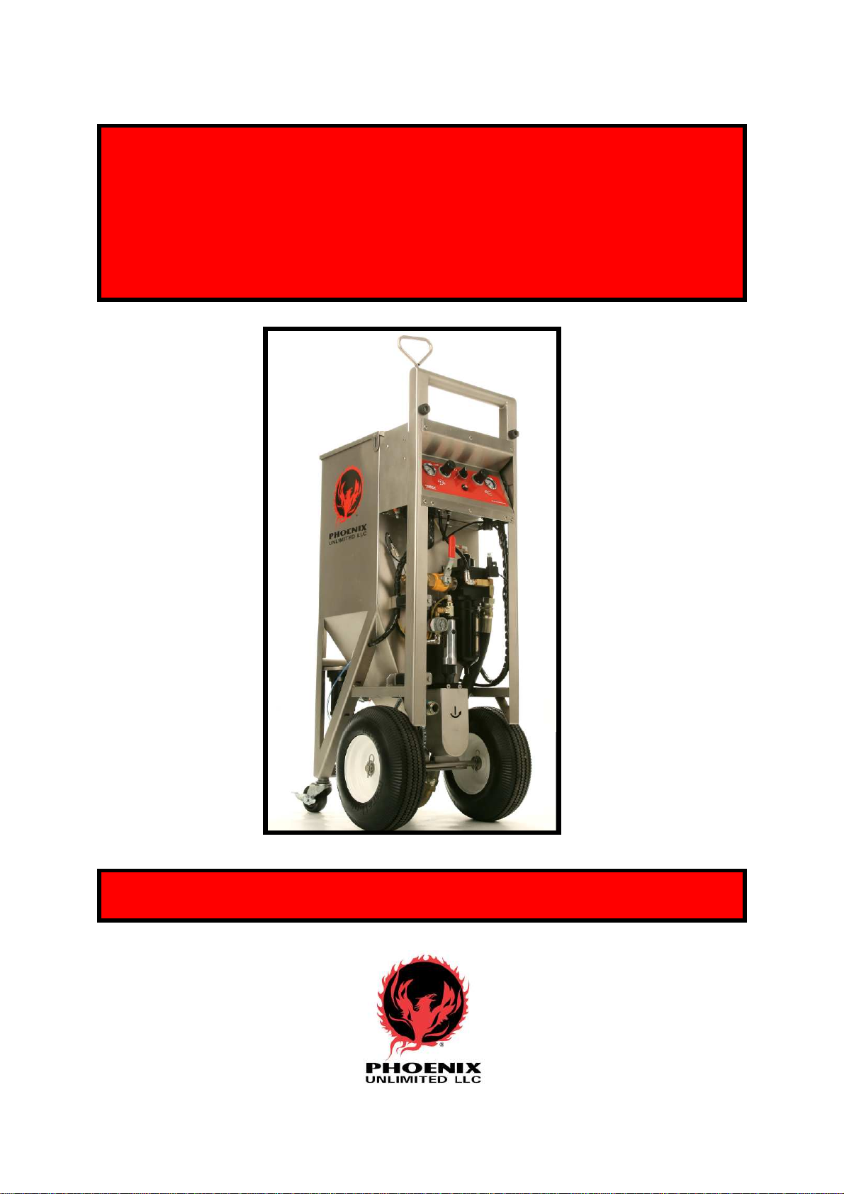
PHX
-
150
Dry Ice Cleaning System
U S E R ’ S G U I D E
30295-UG-040517
Page 2

****************************************************TTAABBLLEEOOFFCCOONNTTEENNTTSS*************************************************
SYSTEM I.D. …………………………………………………… Page 3
EQUIPMENT WARRANTY…………………………………… Page 4
INTRODUCTION ……………………………………………… Page 5
SAFETY PRECAUTIONS AND WARNINGS……….……… Page 6, 7
KEY COMPONENT I.D. ………..………………………..…… Page 8
CONTROL PANEL/WARNING LABEL ….………………… Page 9
OPERATION INSTRUCTIONS
Connecting the Air Supply ………………………..…………. Page 10
Connecting the Blast Gun …………………………...……….. Page 11
Loading Dry Ice ………………………………………………. Page 12
Setting the Panel Controls ……………………………..…….. Page 13, 14
Temporary Shutdown ………………………………….…….. Page 15
Overnight / Long Term Shutdown ……………………..……. Page 16
MAINTENANCE
Daily Preventive Maintenance ………….………………...….. Page 17
As Needed Maintenance
Emptying the Separator……………………………………. Page 18
Changing the Separator Filter Element………………...… Page 18
Changing the Inline Filter Element (Trigger Line) …...…. Page 18
Changing / Adding 10W Oil ……………………………..… Page 19
Checking / Adjusting the Drive Chain Tension…………... Page 19, 20
Periodic Maintenance
Replacing/Servicing Airlock Critical Components………... Page 21-24
*
Page 2
TROUBLESHOOTING CHART ……………………….…..… Page 26, 27
DRAWINGS / PARTS LISTS
Drawing Reference ……………………………………...…... Page 28
Control Panel Assembly ……………………………….……. Page 29
Control Shelf Assembly ……………………………….. .….. Page 30
Vibrator Assembly …………….……………………..……… Page 31
Air System Assembly …….……………………...……..….... Page 32
Filter/Regulator Assembly ….. …………………….………. Page 33
Auger Drive Assembly ………………………………….…… Page 34
Airlock Assembly ………………………………..……..……. Page 35
Auger Section……..……………………………………....…. Page 36
Gun Assembly …………………………………………..…. Page 37-38
Tube Diagram / Factory Settings…………..……………….. Page 39-43
RECOMMENDED SPARE PARTS …………………..…..…. Page 44
SPECIFICATIONS …………………………………….…..….. Page 45
**************************************************************************************************PPHHXX--115500*******************
*
Page 3

SYSTEM I.D.
This User’s Guide is printed for use with the following dry ice cleaning system:
Model: PHX-150
Part Number: 30295-001
Serial Number: 30292
Manufacturing Date: 04/17
U.S. Patent No. 6,346,035
It is recommended that the above information be kept in a safe place. Have it readily
available when utilizing the services of the manufacturer with regards to technical
support, service, parts, etc.
The written material herein contains proprietary information intended for the sole use of
the original owner. It may not be duplicated or disclosed to other parties.
Inspected By: __________________________ Date: __________________________
©2017 Phoenix Unlimited LLC. All rights reserved.
Federal law provides severe civil and criminal penalties for the unauthorized
reproduction or distribution of copyrighted material.
**************************************************************************************************PPHHXX--115500*******************
*Page 3
Page 4

Phoenix Unlimited LLC Equipment Warranty
Phoenix Unlimited LLC (the Company) warrants that the Equipment it manufactures and
delivers hereunder will be free of defects in material and workmanship for a period of
twelvemonths or 2000 hours of operation from the date of shipment, whichever occurs first.
Upon written request, Phoenix Unlimited shall, at its option, correct any nonconformity by
suitable repair to such Equipment, or furnish a replacement part F.O.B. point of shipment,
provided the Purchaser has stored, installed, maintained and operated such Equipment in
accordance with good industry practices and has complied with specific recommendations
of the Company. The Company shall not be liable for any repairs, replacements, or
adjustments to the Equipment or any costs of labor performed by the Purchaser or others
without the Company's prior written approval. The effects of corrosion, erosion and normal
wear and tear, are specifically excluded from warranty.
Correction by the Company of nonconformities whether patent or latent, in the manner and
for the period of time provided above, shall constitute fulfillment of all liabilities of the
Company for such nonconformities, whether based on contract, warranty, negligence,
indemnity,or strict liability with respect to or arising out of such Equipment.
The Purchaser shall not operate Equipment which is considered to be defective without first
notifying the Company in writing of its intention to do so. Any such use of Equipment will
be at the Purchaser's sole risk and liability and will void warranty coverage.
Page 4
Accessories or equipment furnished by the Company, but manufactured by others, shall
carry whatever warranty the manufacturers have conveyed to the Company and which can
be passedon to the Purchaser.
The Companymakes no otherwarrantyor representation of any kindwhatsoever,
expressed or implied,except that of title,and all implied warrantiesof merchantability
and fitness for a particular purposeare herebydisclaimed.
**************************************************************************************************PPHHXX--115500*******************
*
Page 5

INTRODUCTION
Congratulations on choosing the new PHX-150 dry ice cleaning system for your
industrial cleaning needs. Its’ unique design and variable logic control make it the perfect
choice for a wide range of applications, and in any type of environment. Using rice-sized
dry ice pellets, this versatile blasting machine not only handles your tough cleaning jobs;
it cuts your overhead costs in the process. Smart design, powerful, and portability too…
an industrial piece of equipment that will last for many years to come!
You are now ready to learn how to use your new PHX-150.
Before you attempt to operate the equipment, we recommend that you take the time to
fully familiarize yourself with the contents of this User’s Guide. The information
contained in this guide can save invaluable time by helping you gain a clear
understanding of the installation, safety, operation, and maintenance procedures.
Note: Pay particular attention to the sections on “Safety Precautions and Warnings”,
outlined on the following two pages.
Once you are comfortable with the information provided, you will be ready to say
goodbye to old-fashioned methods of cleaning and begin using your new dry ice blaster.
With proper equipment care, you will soon see that the PHX-150 is one tool you cannot
be without.
If you have questions concerning the installation, operation, or information contained in
this User’s Guide, please contact ‘Phoenix Unlimited LLC’ at: (951) 278-2229.
Customer support and technical assistance is always available.
Enjoy!
*****************************************************************************************************************
*
PPHHXX--115500*******************
*Page 5
Page 6
SAFETY PRECAUTIONS AND WARNINGS
User’s Guide Information
Dry ice cleaning equipment should not be operated without proper training and the
consent of your direct supervisor or management. The information contained in the
User’s Guide will provide all the tools necessary for proper operation, safety,
maintenance, and troubleshooting of the equipment. Read and understand the contents of
this guide before using or servicing your machine.
Equipment Usage
Your new cleaning system was designed for use in an industrial environment. Proper safety precautions
should be practiced, observed, and monitored at all times. Be especially careful when blasting around
materials that can shatter. Dry ice blasting adapts to many types of applications, but the high velocity
pellets can cause damage to fragile items or substrates of low integrity. Remember NEVER to direct the
blast stream at yourself or others.
Asphyxiation Hazard
Sublimation of dry ice creates CO2gas. This gas is 40% heavier than air, and thus
displaces oxygen in low-lying areas and enclosed spaces. When blasting, always have
adequate ventilation in and around your workspace. Contaminated compressed air (or
nitrogen) used as a propellant may greatly increase respiratory risk. A “High CO2”
sensor/monitor with indicators is a worthwhile investment and can help prevent
accidental asphyxiation.
Noise
Blasting equipment generates a high velocity air flow from the nozzle. This air flow creates friction as it
passes through normal static air, resulting in high decibel noise levels. Though these levels can be
controlled somewhat by altering pressures and flow rates, ear protection is required in all blasting
situations. Additional noise factors include the object being cleaned, distance from the targeted material,
media quantity being used (ice rate), and acoustic surroundings. If you are unsure about blasting in an area
around you or fellow co-workers, consult with your safety director for advice and/or safety parameters
before beginning work.
Page 6
Emergency Stop Mechanisms
Your unit is equipped with an Arm/Disarm switch located in the center of the control panel. Under normal
use, this switch acts as a convenient way to quickly interrupt power to your PHX-150. However, the true
designated E-STOP is the full-flow valve (bright yellow with a red handle) located on the air system
manifold under the control panel. This valve must be closed before attempting maintenance work or
repairs. A 5/16” hole is provided in the handle to accommodate your company lockout procedures, if
applicable. Raise the locking tab to re-open the valve.
Protective Gear
Before beginning work, make sure you have the proper protective gear for the job. This
includes the basics: Ear plugs or muffs (or both), eye protection, gloves, long sleeves,
long pants, and safety shoes. Dependant upon specialized cleaning jobs, you may also
need other protective items such as: self-contained breathing apparatus, respirator,
grounding straps, skin protectors, jumpsuit, special clothing, or other equipment as
deemed necessary by your company’s safety regulations.
**************************************************************************************************PPHHXX--115500*******************
*
Page 7
Ergonomics
The training process for using your new PHX-150 is relatively easy, but there will still be a “learning
curve” where technique and experience is concerned. The operator should understand that high velocity air
exits the gun barrel. Upon triggering the gun, the operator will experience a small reactive thrust, which
increases or decreases depending on pressure settings and air flow. Operator fatigue may also be an issue,
relating to blasting angles, pressure settings, dwell times, work area, temperatures, physical conditioning,
and time on duty. Do not exceed allowable limits as set by company policy and safety personnel.
High Velocity Particles
High velocity particles exiting the gun may cause serious injury. Never aim the gun at
yourself or others. The ice is sometimes difficult to see in the blast stream. However,
never use your hand, foot, or any other body part to check pellet flow. Do not blast
delicate or fragile items or equipment parts (i.e. glass or plastic gauge faces). Damage
may occur.
Moving Parts
Though the moving parts inside your PHX-150 are minimal, they are critical components and serious injury
may occur if safety parameters are not adhered to. Your machine incorporates an auger that turns, feeding
dry ice pellets into the delivery system. A safety sensor is activated to immediately stop the auger from
turning anytime the pellet screen is removed. Do not attempt to override this sensor. The auger drive motor
and chain are shielded by a protective guard and should never be operated without the guard in place. Do
not attempt to operate the airlock assembly while detached from unit. Always follow shut-down procedures
before attempting any periodic maintenance or repairs.
Burn Hazard
Dry ice is extremely cold, -109°F (-78°C). Do not allow skin to directly contact dry ice or
the outside of the PHX-150 hopper while it is loaded with dry ice. Doing so may cause
severe deep tissue burns. Always wear heavy-duty insulated gloves and long sleeved
clothing for protection when handling dry ice or cold equipment during use.
Static Discharge
The gun of the PHX-150 is grounded through the blast hose to the frame, then through
the special conductive front wheels; therefore any significant amount of static discharge
is uncommon. Still, the possibility exists that minor static discharges can occur pending
weather conditions, the travel of high velocity ice particles, etc. If static discharge is
experienced, wear the grounding wrist strap supplied with your unit. Also, you may wish
to add an additional wire from the machine to a good earth ground, AND ground the item
that you are blasting.
Caution: Static discharge may ignite flammables. Be aware of your surroundings!
Lower Limit Blast Pressure
The PHX-150 utilizes an additional regulator that maintains the blast pressure at 45 psi, even though it is
turned all the way down. When conducting function tests while the unit is energized, take the necessary
precautions to insure that the blast gun is secured and pointed in a safe direction.
Logic Control Stored Air Hazard
The control circuitry of this machine may trap air in and between associated components. Vent unit before
any maintenance or service is performed to prevent accidental release of trapped air.
Lock Out/Tag Out Precaution
Do not perform any type of service to this equipment until all lock out/tag out procedures have been
followed according to your company’s safety regulation guidelines. As mentioned previously (page 6),
a lock out hole (5/16”) is provided in the E-Stop valve handle if required.
**************************************************************************************************PPHHXX--115500*******************
*Page 7
Page 8
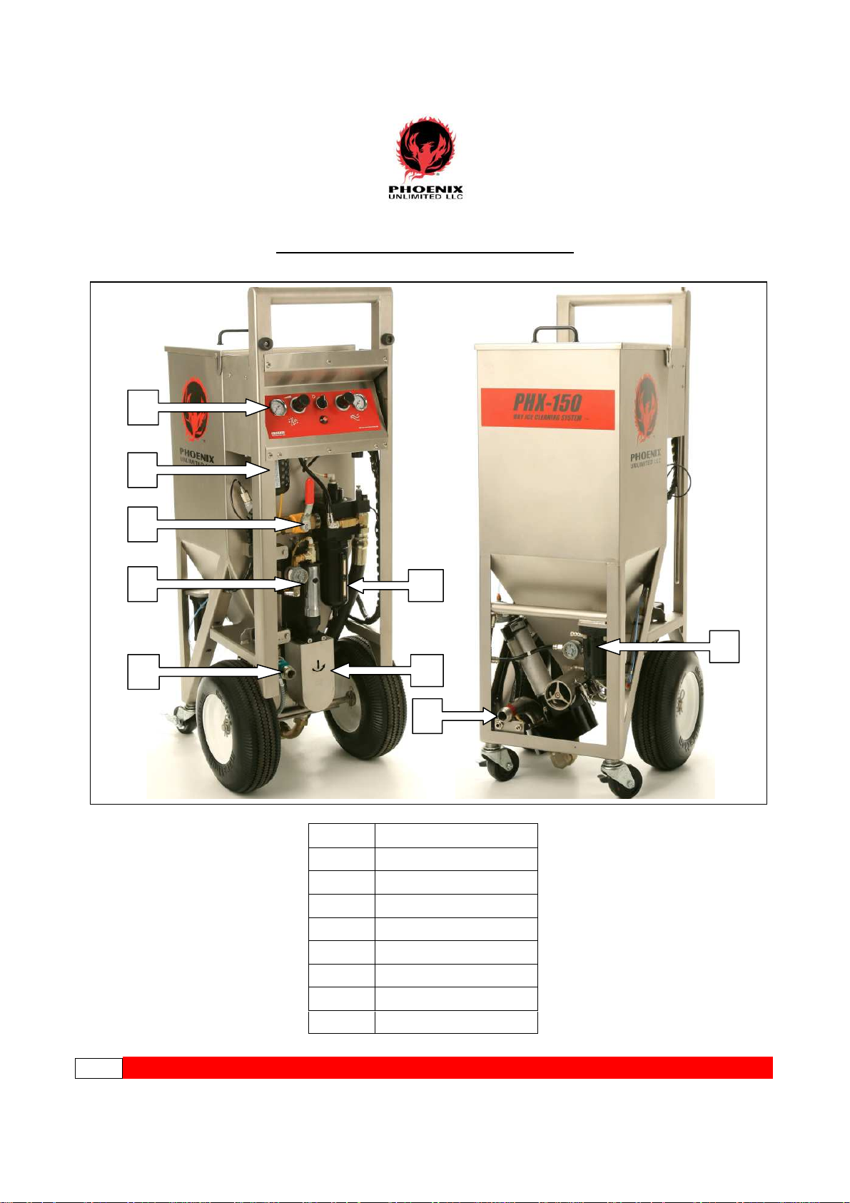
KEY COMPONENT IDENTIFICATION
1
2
3
5
4
9
6
7
8
1
Control Panel
2
Lubricator
3
E-Stop Valve
4
Separator/Regulator
5
Ratchet Motor
6
Auger Drive/Chain Guard
7
Air Supply Inlet
8
Airlock Assembly
9
Vibrator Assembly
Page 8
**************************************************************************************************PPHHXX--115500*******************
*
Page 9
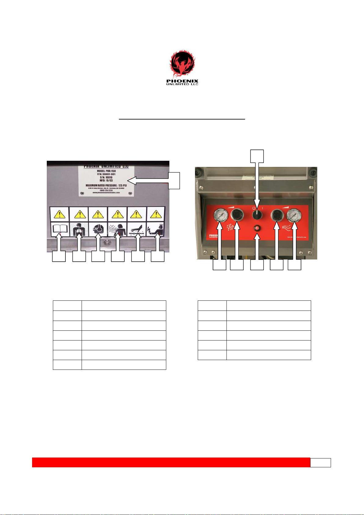
CONTROL PANEL/WARNING LABEL
Hig
h Velocity Particles
Pressure Indicator
7
1 2 3 4 5 6
3
1 2 5 6
4
1
Read User's Guide Information
2
Asphyxiation Hazard
3
Wear Proper Protective Gear
4
5
Burn Hazard
6
Static Discharge
7
Equipment I.D. Tag
1
Ice Rate Gauge
2
Ice Rate Regulator
3
Arm/Disarm Switch
4
5
Blast Air Regulator
6
Blast Air Gauge
**************************************************************************************************PPHHXX--115500*******************
*Page 9
Page 10
OPERATING INSTRUCTIONS
This User’s Guide is the best tool available during the initialization of your new PHX150 Dry Ice Cleaning System. It contains all the information necessary for the proper
installation, safety, operation, maintenance and troubleshooting right at your fingertips.
Familiarize yourself with its’ contents before operating this equipment.
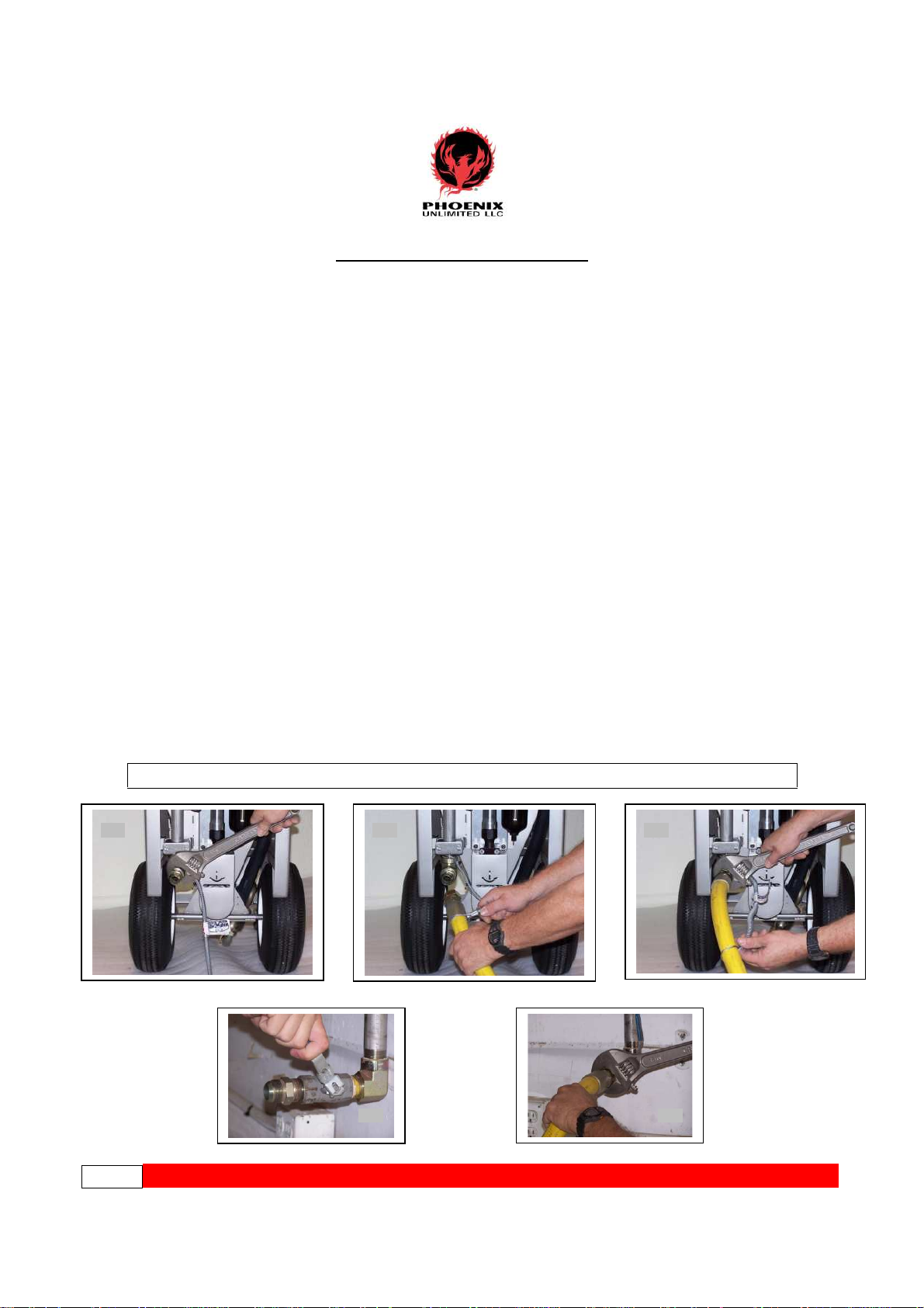
CONNECTING THE AIR SUPPLY
Since the PHX-150 is an “all pneumatic” design, it is critical that only clean, dry air be
supplied to the unit. Air containing excess amounts of moisture, oil, rust, or other
contaminants may clog filters and damage the logic control and internal components. A
good desiccant or refrigerant dryer should be installed between your compressor and the
PHX-150. The dew point should not exceed +40°F/+4.4°C. Good air quality will save
you time for repairs and increase the life of the unit.
1. Install a 1” JIC/NPT male fitting into the supply inlet of the PHX-150. Be careful
with other types of common connectors as they often have gaskets or other restrictive
material, which prevent full air flow. This can drastically reduce your unit
performance level. (pic 1)
2. Install the whip check over the end of the 1” air supply hose. (pic 2)
3. Connect air supply hose to the JIC fitting and extend the whip check as far down the
hose as possible. (pic 3)
4. Wearing hearing protection, blow down the air source at the drop to remove any
accumulated moisture. This helps to insure equipment performance. (pic 4)
5. Connect the air supply hose to the air source. (pic 5)
Caution! Maximum air pressure supplied to the PHX-150 should never exceed 125 psi!
Pic 1 Pic 2 Pic 3
Pic 4 Pic 5
Page 10
**************************************************************************************************PPHHXX--115500*****************
*
Page 11
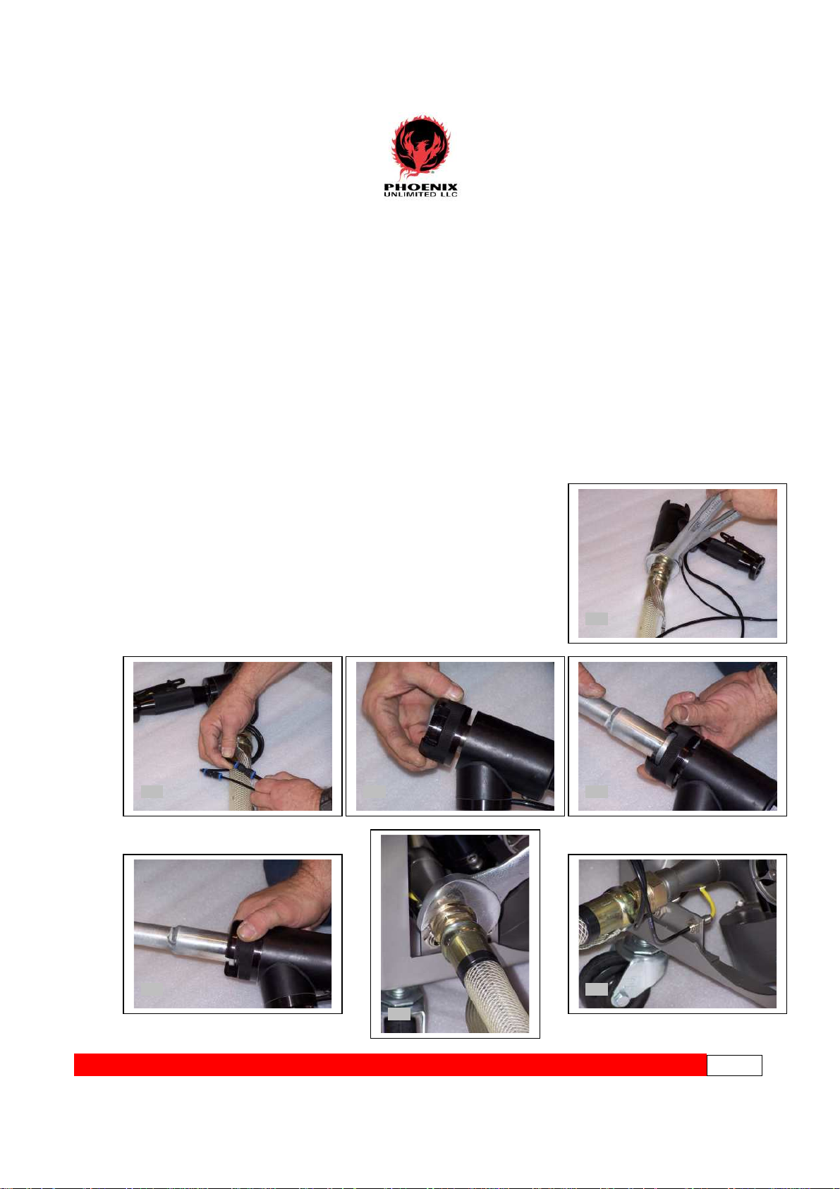
CONNECTING THE BLAST GUN
1. Use 1¼” and 1½” wrenches to connect the gun to the end of the blast hose with the
shorter length trigger lines. Do not over-tighten. (pic 1)
2. Connect the respective trigger lines (different sizes) to the gun, pushing firmly into the
quick-connect fittings. (pic 2)
3. Install the nozzle by a) twisting threaded retainer to completely ‘open’ position;
b) place nozzle into end of blast gun; c) tighten retainer to secure the nozzle. Improper
seating of the nozzle in the gun may result in air leakage. (pics 3, 4, 5)
4. Using the 1½” wrench, connect the remaining end of the blast hose to the front of the
PHX-150. (pic 6)
5. Connect the two trigger lines to the unit, pushing firmly until seated. Failure to attach
trigger lines will result in the non-functioning of the unit. (pic 7)
6. If necessary, ground the item you are blasting.
Pic 1
Pic 2 Pic 3 Pic 4
Pic 5
Pic 6
Pic 7
**************************************************************************************************PPHHXX--115500*****************
*Page 11
Page 12
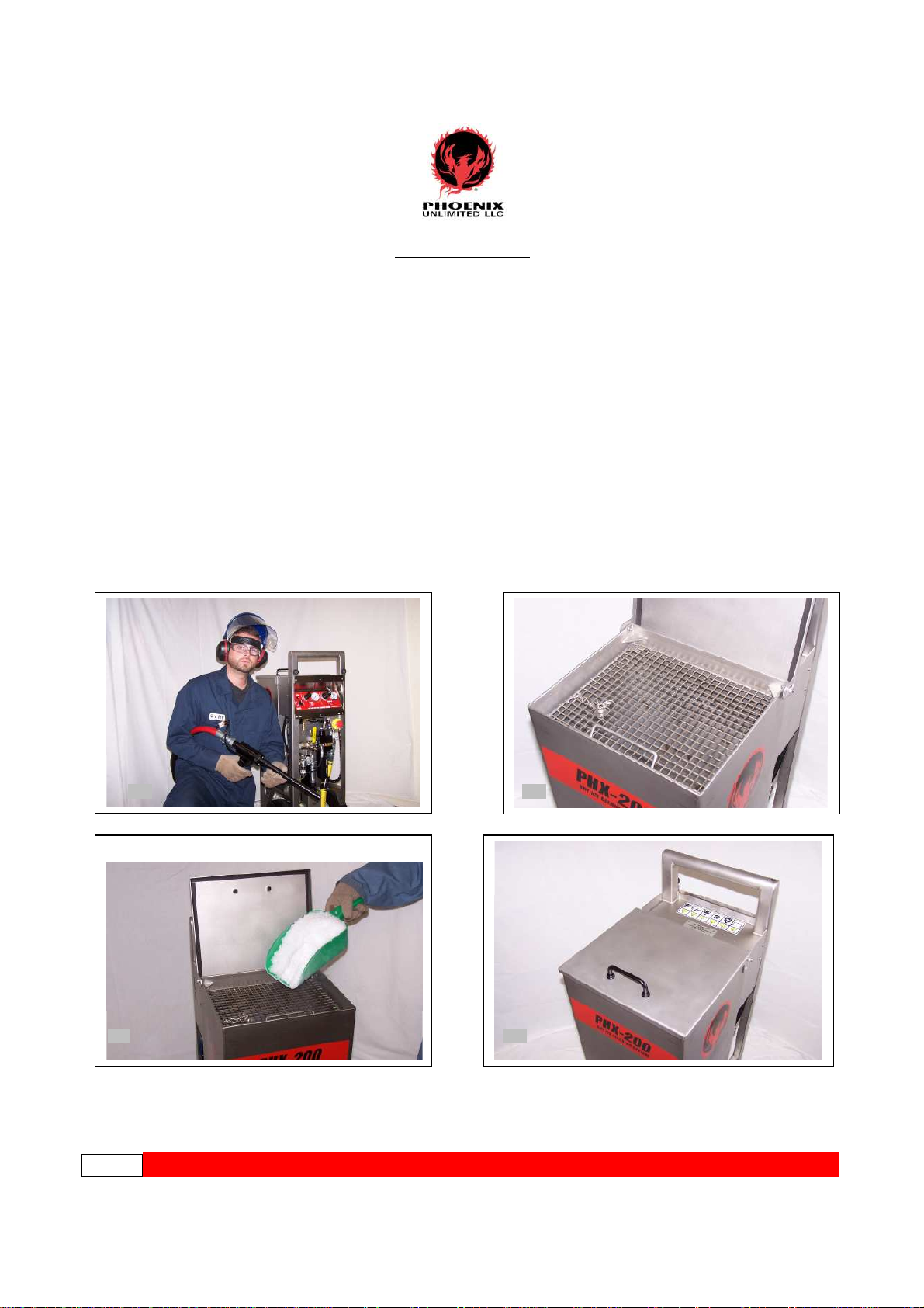
LOADING DRY ICE
1. Before you begin loading dry ice, it is important that you have the protective gear
previously mentioned in the “Safety Precautions and Warnings” section (page 6).
This includes basic items such as earplugs or muffs (or both), eye protection, face
shield, heavy-duty gloves, long sleeves, long pants, and safety shoes. (pic 1)
2. Lift hinged metal lid to expose hopper. BE AWARE OF AND KEEP CLEAR OF
PINCH POINTS (pic 2)
3. Use a sturdy scoop or similar device to load dry ice pellets into the hopper. (pic 3)
Be careful not to inhale concentrated CO2gas during the loading process, as it will
temporarily rob you of oxygen. If overexposed, get fresh air immediately. Signs
of overexposure include dizziness, cold sweats, headaches, nausea, and heavy
breathing.
4. Close the lid on the hopper. This will prevent airborne contaminants from
inadvertently falling through the pellet screen to the ice and ultimately ending up
on the surface you are cleaning or damaging internal airlock parts. (pic 4)
Pic 1 Pic 2
Page 12
**************************************************************************************************PPHHXX--115500*****************
Pic 4Pic3
*
Page 13
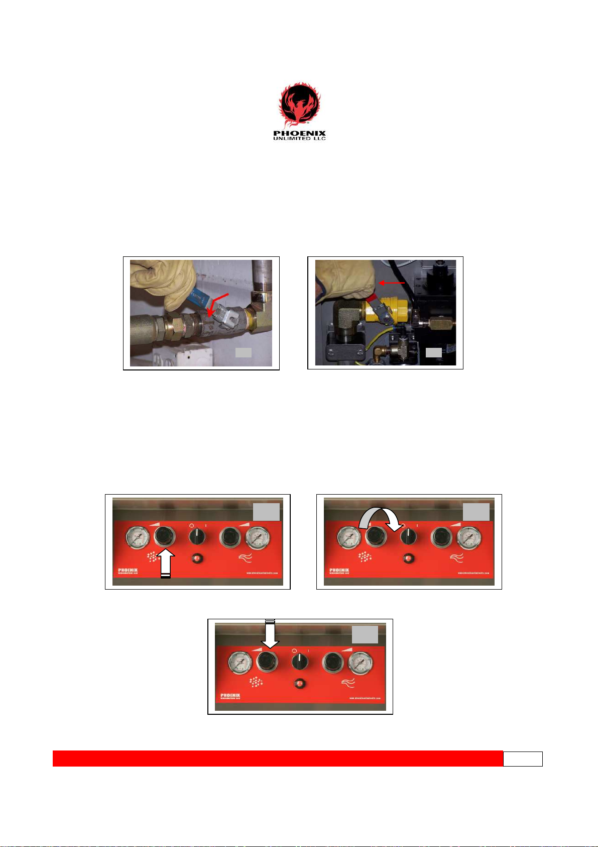
SETTING THE PANEL CONTROLS
Applying Air to the Unit
1. Slowly open the main air supply valve (source). (pic1)
2. With the gun pointed in a safe direction, slowly open the E-Stop valve on the
PHX-150. (pic 2)
Pic 2Pic 1
Setting the Panel Controls
1. Pull the ‘Ice Rate’ knob outwards to unlock it. (pic 1)
2. Turn the control clockwise until the gauge reaches the desired pressure. If unsure, start
at about 25 psi, then adjust the rate up or down as necessary for your particular blasting
application. (pic 2) Note: Trigger on gun must be pulled in order for gauge to read!
3. Push the knob in to lock the ice rate. (pic 3)
Pic 2Pic 1
Pic 3
**************************************************************************************************PPHHXX--115500*****************
*Page 13
Page 14

SETTING THE PANEL CONTROLS (cont.)
4. Next set the blast pressure. Pull the ‘blast pressure’ knob outwards to unlock it. (pic 4)
5. Turn the knob clockwise until desired pressure is reached. The PHX-150 has a blast
pressure range from 45 psi to 125 psi. Satisfactory results are generally achieved in the
80-100 psi range for most applications. If you are unsure or concerned about damage to
the item being blasted, start at a lower blast pressure and increase it gradually until the
optimum performance level is achieved. (pic 5)
6. Push the knob in to lock the blast rate. (pic 6)
Note: The PHX-150 utilizes an additional regulator that maintains the blast pressure at
45 psi, even if the control panel knob is turned all the way down. This prevents “freezeups” in the airlock assembly, which will occur if ice continually feeds without
sufficient pressure to propel it to the gun.
7. Turn the Arm/Disarm switch clockwise to arm the PHX-150. The indicator will turn
green, and the momentary switch will return to the center position. (pic 7)
8. Point the gun at the target or in a safe direction. Push upwards on the safety catch to
release and pull the trigger to initialize blasting. (pic 8)
Pic 4 Pic 5 Pic 6
Pic 4 Pic 5 Pic 6
Pic 7 Pic 8
Pic 7
Page 14
**************************************************************************************************PPHHXX--115500*****************
*
Page 15

TEMPORARY SHUTDOWN
1. When blasting is complete, release the trigger and wait for airflow to stop. (There is a
short delay while residual ice is purged from the blast hose. Keep gun pointed at the
target until air stops flowing!) (pic 1)
2. Turn the Arm/Disarm switch counter-clockwise. The indicator will turn red, and the
momentary switch will return to the center position. (pic 2)
3. Close the air supply valve at the source. Important! Failure to disconnect the source
end of the air supply first may create potential “air entrapment” or “hose whip”
hazards! (pic 3)
4. Vent remaining air from the machine and supply hose by closing the
E-Stop valve approximately halfway. (pic 4)
5. After the air stops flowing, you may fully close the E-Stop valve. (pic 5)
6. If moving the unit to another location for blasting, disconnect the supply hose at the
source and wrap around the machine handle for quick transport. It is not necessary to
disconnect the hose from the unit unless storing overnight or long term. (pic 6)
Pic 1 Pic 3
Pic 4 Pic 5
Pic 2
**************************************************************************************************PPHHXX--115500*****************
Pic 6
*Page 15
Page 16

OVERNIGHT / LONG TERM SHUTDOWN
1. If you won’t be blasting again soon, release the trigger and wait for airflow to stop.
(There is a short delay while residual ice is purged from the blast hose. Keep gun pointed
at the target until air stops flowing!) (pic 1)
2. Turn the Arm/Disarm switch counter-clockwise. The indicator will turn red and the
momentary switch will return to the center position. (pic 2)
3. Remove any unused ice from the hopper with a scoop and return it to the storage
container.
4. Turn the Arm/Disarm switch clockwise. Indicator will turn green. (pic 3)
5. Pull the trigger and expel remaining pellets through the gun. (pic 4)
6. Follow steps 2-6 on page 15 to complete the shutdown procedure, then store unit. (text
box)
Pic 1
Pic 3
FOLLOW STEPS
2-6 ON PAGE 15
TO COMPLETE
Pic 2
Pic 4
Page 16
**************************************************************************************************PPHHXX--115500*****************
*
Page 17

MAINTENANCE
CAUTION! Do not attempt to perform any maintenance or service on your PHX-150
unless safety guidelines and lock out/tag out procedures have been satisfactorily met!
DAILY PREVENTIVE MAINTENANCE
Before starting the machine each day/shift, a quick preventive maintenance inspection
should be performed to ensure that your unit operates problem-free now and in the future.
1. Check the separator sight glass for accumulated moisture or remove the canister to
inspect the filter for contamination. Clean canister if needed. (See page 18 for filter
replacement procedure). (pic 1)
2. Visually inspect lubricator to confirm fluid level is adequate. (pic 2)
3. Inspect hose assembly for cracks or leaks. Replace if necessary. (pic 3)
Pic 1 Pic 2 Pic 3
AS NEEDED MAINTENANCE
Separator / Auto-Drain Leak Check
The PHX-150 features an “auto-drain” in the separator to relieve excess moisture during
normal use. The float mechanism should be securely in place with no air leakage under
pressure. To check:
1. Slowly open the main air supply valve. (pic 1)
2. Slowly open the E-Stop valve of the PHX-150. (pic 2)
3. Check for air leakage under pressure. If air is present, you may need to clean the auto-
drain or replace. Tighten the drain nut securely after replacement. (pic 3)
Pic 1 Pic 2 Pic 3
************************************************************************************************PPHHXX115500*****************
*
PPaaggee117
7
Page 18

Changing the Separator Filter
To ensure that your dry ice cleaning system operates correctly and continues to provide
reliable performance levels, the separator needs to be inspected regularly. Poor filtering
leads to excessive moisture being passed into the control system, airlock, blast gun, and
ultimately to the targeted surface. A discolored filter element should be replaced. Follow
this simple procedure:
1. Press locking tab on separator canister and turn in either direction to disengage. (pic 1)
2. Lower the canister to expose filter element. (Empty any accumulated moisture in
canister before reinstalling). (pic 2)
3. Remove element retainer umbrella by turning counter-clockwise. (pic 3)
4. Remove old filter element, pulling straight down and away. (pic 4)
5. Install new element by reversing steps 1-4.
Pic 1
Pic 2 Pic 3 Pic 4
Changing the Inline Filter Element (Trigger Line)
If the unit is ready to blast (Arm/Disarm indicator is green), but does not start when the
trigger is pulled, it may indicate the need to change the trigger line inline filter element.
To perform this:
1. Locate the filter housing on inner leg of the PHX-150 near the trigger connectors. (pic1)
2. Disconnect the tubing from filter housing push fittings (both ends), then remove filter
housing from unit. (pic 2)
3. Using two ¾” wrenches, remove the cap from the filter housing to expose the sintered
bronze filter element. (pic 3)
4. Remove filter element. Important: Remember proper configuration of internal spring
in relation to the element. Improper installation will result in the non-operation of the
unit. (pic 4)
5. Install new filter element and housing by reversing steps 2-4.
Pic 1 Pic 2
Pic 3 Pic 4
Page 18
**************************************************************************************************PPHHXX--115500*****************
*
Page 19

Changing / Adding 10W Oil
1. Turn the lubricator retaining ring counter-clockwise by hand, then lower the
bowl/housing away from suction wick. (pic 1)
2. Add 10W tool oil (or equivalent) until level with fill line. (pic 2)
3. Be sure that the O-ring is properly seated in the top of the lubricator bowl. (pic 3)
4. Reinstall the bowl/housing into place. Hand tighten only. Do not over tighten. (pic 4)
Pic 1 Pic 2 Pic 3 Pic 4
Checking / Adjusting the Drive Chain Tension
1. Use a 5/32” hex key wrench to loosen two screws located at the top of the motor/chain
guard. Do not remove the screws. (pic 1)
2. Gently tilt the unit forward and remove third screw located at the bottom of the guard.
(pic 2)
3. Remove the chain guard to reveal drive chain. (pic 3)
4. Apply pressure to mid-span point. Movement should not be more than 3/32”. (pic 4)
5. If tension adjustment is necessary, loosen the two upper hex screws on the motor
mounting plate. (pic 5)
6. Locate the drive chain adjustment screw at the very top of the motor mounting plate.
(pic 6)
(continued)
Pic 1 Pic 2 Pic 3
Pic 4 Pic 5 Pic 6
**************************************************************************************************PPHHXX--115500*****************
*Page 19
Page 20

Checking / Adjusting the Drive Chain Tension (cont.)
7. Use a 7/16” box wrench to loosen the adjustment screw retaining nut by turning
counter-clockwise. (pic 7)
8. Hold the retaining nut in position and use a 3/16” hex key wrench to adjust the screw
(clockwise to increase tension, counter-clockwise to relieve) until proper tension is
achieved. (pic 8)
9. Tighten the retaining nut to lock the adjustment screw into place. (pic 9)
10. Tighten the two upper hex screws on the motor mounting plate. (pic 10)
11. Verify that the auger directional switch on motor ratchet is rotated fully clockwise.
(pic 11)
12. Install the motor/chain guard into position. (pic 12)
13. Tighten the three screws that secure the guard into place. (pic 13)
Pic 7 Pic 8 Pic 9
Page 20
Pic 10
Pic 11 Pic 12
VIBRATOR
The Vibrator Pad (30031-001) will wear over time allowing the piston to strike
the bare frame metal. The Pad can be replaced by removing the four mounting bolts.
The Vibrator can be service by removing it from the frame. Remove the two
screws that secure the end cap. Use caution not to tear the gasket and remove end cap.
Remove piston and clean any debris and rust from bore and piston using ATF fluid.
Reassemble piston and end cap. Piston should move freely. Reinstall unit to frame.
**********************************************************************************************PPHHXX--115500*****************
*
Page 21

PERIODIC MAINTENANCE
CAUTION! Do not attempt to perform any maintenance or service on your PHX-150
unless safety guidelines and lock out/tag out procedures have been satisfactorily met!
Replacing Airlock Critical Components
Diminished performance or a noticeable drop in blast pressure at the gun may indicate a
worn or damaged component in the airlock. Most airlock problems are typically caused
by a foreign object (airborne or otherwise) falling through the hopper pellet screen,
mixing with the dry ice pellets, and becoming lodged inside the airlock or doing damage
as it passes through to the blast hose and gun. (Note: You can avoid unnecessary
expense and repairs by closing the hopper lid after filling with ice and prior to
blasting.) In order to properly inspect or replace the critical components, the airlock
assembly must be removed from the unit. To do this:
1. Remove air supply hose from the PHX-150. Also remove the gun and blast hose
assembly if attached. (pic 1)
2. To avoid spillage, remove the lubricator bowl/housing and set aside. (pic 2)
3. Carefully place the unit flat on the ground with the control panel facing down.
(pic 3). Be careful that hinged metal lid does not “flop” backwards suddenly during this
procedure.
4. Detach the inlet blast air hose coupling from airlock assembly inlet. (pic 4)
5. Remove the airlock motor air supply line from the push fitting. (pic 5)
6. Remove the large cotter pin from the airlock retaining latches. (pic 6)
Pic 1 Pic 2 Pic 3
Pic 4 Pic 5 Pic 6
**************************************************************************************************PPHHXX--115500*****************
*Page 21
Page 22

Replacing Airlock Critical Components (cont.)
7. Open airlock retaining latches. (pic 7)
8. Remove complete airlock assembly from unit and move it to a workbench. (pic 8)
9. Use a 3/16” hex key wrench to remove six housing bolts from bottom of airlock
assembly. (pic 9)
10. Separate the housing and set bottom half aside. (pic 10)
Pic 7 Pic 8 Pic 9 Pic 10
Rotor:
11. Carefully remove the rotor from the
spline and inspect. Replace if damaged.
Before installation of new rotor, clean and
inspect the pads, motor, spline and internal
walls of the housing for damage. If all parts
are good, install the new rotor onto the
spline. (pic 11)
12. Reinstall airlock assembly onto the
Pic 11
REINSTALL
AIRLOCK
ASSY. BY
REVERSING
STEPS 1-10
PHX-150 by reversing steps 1-10. (text box)
Page 22
Airlock Motor / Spline:
13. While the housing is disassembled, inspect the motor and spline. If replacement is
necessary, the motor will need to be removed from the housing. (pic 12)
14. Use a ¼” hex key wrench to remove the two mounting screws, then remove the motor
assembly from the housing. (pic 13)
15. Use two wrenches to remove the spline from the motor and install new one.
16. Be sure centering ring is in place and reinstall motor to housing.
17. Reinstall airlock assembly by reversing steps 1-11
REINSTALL
AIRLOCK
ASSY. BY
REVERSING
Pic 12 Pic 13
STEPS 1-11
**************************************************************************************************PPHHXX--115500*****************
*
Page 23

Replacing Airlock Critical Components (cont.)
Airlock Pads:
17. While the housing is disassembled, inspect the airlock pads (2) located in each half of
the housing. If damaged, they must be replaced. (pic 15)
18. Remove the pads from the housing. (pic 16)
19. Inspect the O-rings on both pads. Replace if worn or damaged. Before installing new
O-rings (or re-using existing ones), apply a thin coat of Dow-Corning 33 lubricant.
(pic 17)
20. Make sure that O-rings are seated properly in the pads. (pic 18)
21. Carefully install the pads into the airlock housing. Fully installed, they will be flush
with the housing walls, with no part of the O-rings showing. (pic 19)
22. Reinstall airlock assembly onto the PHX-150 by reversing steps 1-11. (text box)
Pic 15 Pic 16
Pic 17 Pic 18
REINSTALL AIRLOCK
ASSY. BY REVERSING
STEPS 1-11
Pic 19
**************************************************************************************************PPHHXX--115500*****************
*Page 23
Page 24

AIRLOCK MOTOR (P/N 50202-001) MAINTENANCE
Engine Lubrication- Be sure air lubricators are maintained as outlined in equipment
manual. If wet dirty air is being used, water, dirt, rust and emulsified oil can accumulate
in lubricator bowls, making it look like they are full of oil. A periodic “closer look” is
recommended and an oil change is recommended if it is contaminated with water.
Cleaning Engine- Water and rust in the compressed air or dust and wear particles can
cause sticking of vanes, valves etc. This can be prevented by removing muffler, flushing
with a few drops of oil, running the motor for 5-10 seconds and absorbing the oil in a
cloth. Replace or reinstall muffler. Protect the engine this way before long shutdown
periods. DO NOT RUN THE AIRLOCK FOR LONG PERIODS WITHOUT ICE.
Muffler-Over time the muffler can become clogged with particles and restrict exhaust
flow which will make the motor run slower. It is recommended to periodically replace the
muffler. (P/N 50203-001)
Maintenance and repairs must be carried out exclusively by authorized personnel.
Overhaul- To achieve the best service life under normal operating conditions, regular
overhaul and cleaning should be carried out every 12 months or 2000 hrs., whichever is
sooner. Overhaul should be carried out more frequently under more rigorous operating
conditions.
Lubrication- Planetary gears, ball and needle bearings and seal ring should be
lubricated with grease in conjunction with the regular overhaul of the motor. Molykote
BR2 Plus gives long intervals between lubrications.
Contact Phoenix Unlimited LLC or a qualified service center for motor overhaul options.
PPaaggee2244************************************************************************************************************************PPHHXX--115500*****************
*
Page 25

5
4
6
7
9
8
1. 50202-001 MOTOR
2. 30281-001 SPLINED SHAFT
3. 30278-001 CENTERING RING
4. 50203-001 MUFFLER
5. 50114-688 ELBOW
6. 50114-158 ELBOW
7. 50004-002 ELBOW
8. 50053-001 VALVE
9. 50015-002 CONNECTOR
10. 50002-F04 PLUG
11. 50057-628 ELBOW
10
11
FOLLOWING ITEMS NOT SHOWN
12. 10020-P12 BOLT (2)
1
2
13. 10018-005 LOCKWASHER (2)
3
PHOENIX UNLIMITED LLC
30275-002A
AIRLOCK MOTOR ASSEMBLY
COMPLETE
**************************************************************************************************PPHHXX--115500*****************
*Page 25
Page 26

TROUBLESHOOTING
Symptom Item Check Corrective Measure
The PHX-150 will
not start.
Air supply valve is not opened.
The unit is not armed (indicator will be
red).
Open the air supply valve (E-Stop valve).
Turn Arm/Disarm switch clockwise (indicator should
turn green).
The PHX-150 starts,
but no ice comes out.
Pellet screen is not properly installed.
Loose or kinked tubing in control panel.
Trigger lines improperly connected.
Trigger valve failure.
Inline filter plugged (trigger return line).
Contamination in the trigger lines.
There is no dry ice in the hopper.
Ice rate is set too low.
Possible ice bridging inside the hopper.
Water ice accumulation in hopper.
Make sure pellet screen fully engages safety interlock
switch when installed.
Check for loose or kinked tubes behind panel.
Reconnect if necessary.
Check trigger lines at machine and at the gun.
Check trigger valve for contamination. Clean or
replace as necessary. Correct cause of contamination.
Check filter and replace element if necessary.
Blow out trigger lines. Correct cause of contamination.
Load fresh dry ice into the hopper.
Turn Ice rate regulator clockwise to increase.
With pellet screen in place, use poker to break up the
bridge. This symptom is generally caused by poor ice
quality and high humidity areas.
Water ice forms in high humidity areas or when ice is
left in the hopper for long periods of time. Clean and
dry the hopper thoroughly before refilling.
Blast gun or hose plugged.
Incorrect auger rotation. (Auger should
turn counterclockwise when viewed from
the rear of the unit).
Airlock is not turning.
Decrease blast pressure to 45 psi. Remove blast hose
from unit. With trigger lines still attached, trigger the
unit to clear ice from the discharge outlet. Reattach
hose and remove nozzle from gun. Trigger again to
clear ice from hose and gun. Reattach nozzle.
Remove motor/chain guard and turn selector switch
on ratchet motor to reverse direction.
See section on “Airlock does not turn”- next page.
PPaaggee2266************************************************************************************************************************PPHHXX--115500*****************
*
Page 27

SSyymmttoommIItteemmCChheecckkCCoorrrreeccttiivveeMMeeaassuurre
PPeelllleettssssttooppfflloowwiinng
aafftteerraappeerriiooddoof
bbllaassttiinngg.
f
.
TROUBLESHOOTING (cont.)
g
TThheerreeiissnnooddrryyiicceelleeffttiinntthheehhooppppeerr.
PPeelllleettsshhaavveebbrriiddggeeddoovveerraauuggeerriinnssiidde
.
hhooppppeerr.
e
.
e
LLooaaddddrryyiicceeiinnttoohhooppppeerr.
WWiitthhppeelllleettssccrreeeenniinnppllaaccee,,uusseeppookkeerrttoobbrreeaakkuupptthhe
bbrriiddggee..PPoooorriicceeqquuaalliittyyaannddhhiigghhhhuummiiddiittyyggeenneerraalllly
ccaauusseetthhiisspprroobblleemm.
.
e
y
.
BBllaasstthhoosseeoorrgguunnpplluuggggeedd.
AAuuggeerrnnoottttuurrnniinngg.
AAiirrlloocckknnoottttuurrnniinngg.
BBllaassttgguunnpplluuggs
rreeppeeaatteeddllyy.
AAuuggeerrddooeessnnoottttuurrnn..IIcceerraatteesseettttoooollooww.
AAiirrlloocckkddooeessnnoottttuurrnn..LLoossssooffaaiirrssuuppppllyyttootthheeaaiirrlloocckkmmoottoorr.
s
.
IIcceerraatteesseettttoooohhiigghh.
PPoossssiibblleewwaatteerriicceeaaccccuummuullaattiioonniinnssiidde
.
gguunn.
IInnccoorrrreeccttddrriivveecchhaaiinntteennssiioonn.
LLoossssooffaaiirrssuuppppllyyttootthheeddrriivveemmoottoorr.
SSuuppppllyyaaiirriissttoooollooww.
.
.
.
.
.
.
.
.
DDeeccrreeaasseebbllaassttpprreessssuurreettoo4455ppssii..RReemmoovveebbllaasstthhoosse
ffrroommuunniitt..WWiitthhttrriiggggeerrlliinneessssttiillllaattttaacchheedd,,ttrriiggggeerrtthhe
uunniittttoocclleeaarriicceeffrroommtthheeddiisscchhaarrggeeoouuttlleett..RReeaattttaacch
hhoosseeaannddrreemmoovveennoozzzzlleeffrroommgguunn..TTrriiggggeerraaggaaiinntto
cclleeaarriicceeffrroommhhoosseeaannddgguunn..RReeaattttaacchhnnoozzzzllee.
SSeeeesseeccttiioonn““AAuuggeerrddooeessnnoottttuurrnn””bbeellooww.
SSeeeesseeccttiioonn““AAiirrlloocckkddooeessnnoottttuurrnn””bbeellooww.
DDeeccrreeaasseeiicceerraattee.
e
DDeeffrroosstt,,cclleeaann,,aannddddrryytthheegguunn..CChheecckkiinnccoommiinnggaaiir
ssuuppppllyyffoorrccaauusseeooffccoonnttaammiinnaattiioonnaannddccoorrrreecctt.
IInnccrreeaasseeiicceerraattee.
CChheecckkaannddaaddjjuussttcchhaaiinntteennssiioonn..((ppaaggeess1199--2200)
CChheecckkssuuppppllyyaaiirrttootthheeddrriivveemmoottoorriinnppuutt..IIffnneeeeddeedd,
ccoonnttaaccttPPhhooeenniixxUUnnlliimmiitteeddffoorrssuuppppoorrtt.
MMaakkeessuurreessuuppppllyyaaiirriissaattlleeaasstt7755ppssiitthhrroouugghhaa11”
uunnrreessttrriicctteeddlliinnee.
.
CChheecckkssuuppppllyyaaiirrttootthheeaaiirrlloocckkmmoottoorriinnppuutt..IIffnneeeeddeedd,
ccoonnttaaccttPPhhooeenniixxUUnnlliimmiitteeddffoorrssuuppppoorrtt.
.
.
.
e
e
h
o
.
.
.
r
.
)
,
.
”
,
.
.
.
.
RReemmoovvee,,ddiissaasssseemmbbllee,,cclleeaann,,aannddrreeiinnssttaallll.
.
RReemmoovveeaaiirrlloocckk,,cclleeaannoorrrreeppllaacceeppaarrttss..((ppaaggeess2211--2233)
s
CChheecckkssuuppppllyyttoovveerriiffyyaa11””uunnrreessttrriicctteeddlliinneeffrroommtthhe
e
uunniittttootthheeccoommpprreessssoorr..DDiissttaanncceessoovveerr110000ffeeeettmmaay
eevveennbbeeooffllaarrggeerrddiiaammeetteerr.
IIfftthheepprreessssuurreeddrroopphhaassaassiiggnniiffiiccaannttaaddvveerrsseeeeffffeecct
oonncclleeaanniinnggppeerrffoorrmmaannccee,,aallaarrggeerrccoommpprreessssoorrmmaay
bbeerreeqquuiirreedd.
.
.
BBllaassttpprreessssuurreeaanndd//oor
iicceerraatteeddrrooppssqquuiicckklly
wwhheennttrriiggggeerriissppuulllleedd.
BBllaassttpprreessssuurreeaanndd//oor
iicceerraatteeddrrooppsssslloowwlly
wwhheennttrriiggggeerriissppuulllleedd.
r
y
r
y
EExxhhaauussttmmuufffflleerriisspplluuggggeedd.
EExxcceessssiivveeccoonnttaammiinnaattiioonnoofftthheeaaiirrlloocckk.
AAiirrssuuppppllyylliinneeiisslleesssstthhaann11””oorrtthheerreeiis
aarreessttrriiccttiioonnssmmaalllleerrtthhaann11””bbeettwweeeenntthhe
.
uunniittaannddtthheeccoommpprreessssoorr.
IInnddiiccaatteessaannuunnddeerrssiizzeeddccoommpprreessssoorr.
.
************************************************************************************************************************PPHHXX--115500*****************
.
)
e
y
t
y
*Page 27
Page 28

PHX-150DRAWING REFERENCE
30089-001
POKER
ASSEMBLY
30029-001
CONTROLPANEL
30016-001
CONTROLSHELF
(BEHINDPANEL)
30024-001
AIRSYSTEM
30006-001
AUGERDRIVE
ASSEMBLY
30100-KIT
HOPPER LIDKIT
20011-K35
BUMPER
30
40
2
0
10
50
0
0
6
PSI
PHOENIX
UNLIMITEDLLC
BLASTAIRICERATE
80
40 120
0
PSI
www.phoenixunlimitedllc.com
6
0
1
PHX-150
DRY ICECLEANING SYSTEM
30060-001
FILTER/REGULATOR
30049-001
AIRLOCK SUPPLYHOSE
30031-001
VIBRATOR PAD
30028-001
VIBRATOR
ASSEMBLY
30016-001
AIRLOCK
ASSEMBLY
20013-012
WHEEL
RIGHT LEFT
30002-002
PELLET/SAFETY
SCREEN ASSEMBLY
30114-001
TRIGGER RETURN
FILTERASSEMBLY
30113-001
AIR TANK
ASSEMBLY
20009-B04
CASTER,
CONDUCTIVE
30003-001
SAFETYSCREEN
VALVE ASSEMBLY
50061-001
HOSE WHIP CHECK
Page 28************************************************************************************************************************PPHHXX--115500******************
Page 29

21
---21
30030
-
001B
CONTROL PANEL, PHX
-
150
1
3
4
5
6
30
2
0
40
10
50
0
6
0
PSI
80
40 120
0
PSI
160
7
8
BLAST AIRICE RATE
PHOENIX
UNLIMIT ED LL C
12 13
10
17
1
11
NC
NO
14
www.phoenixunlimitedllc.com
5
9
************************************************************************************************************************PPHHXX--115500*****************
16
15 14
1515
1 50007-001 LOGIC ELEMENT "OR" 17
1 50016-002 ELBOW 16
3 50018-001 ELBOW, FEMALE 15
2 50057-628 ELBOW 14
1 50011-912 VALVE BODY, NP (NC) 13
1 50110-001 MOUNTING RING, VALVE BODIES/SELECTOR 12
1 50111-911 VALVE BODY, NNP (NO) 11
1 50017-002 TEE 10
1 50027-212 INDICATOR. PRESSURE 9
1 50025-160 GAUGE, BLAST AIR PILOT, 160 PSI 8
1 50051-001 REGULATOR, BLAST AIR PILOT 7
1 50025-060 GAUGE, ICE RATE, 60 PSI 6
2 50069-001 NUT, REGULATOR 5
1 30032-001A REGULATOR, ICE RATE 4
1 50109-005 SELECTOR, ARM/DISARM 3
_-001 Part No. Description Item No.
30029-001D PARTS LIST
*Page 29
Page 30

DATE:
3/3/17
A
1 OF 2
4 REQ
D
25
6 8 9
22
12
8 8 9 8 8
10
26
9
B
23,24,27
NOT
SHOWN
19
a
18
20
a
A
b
a
A
A
b
b
X
a
a
a
A
A
b
b
X
X
a
A
A
b
b
X
a
a
A
A
b
b
X
X
11
23
21
20
1
7
2
5
5
X
b
A
a
3
4
C
(30025-SHELFA)
DRAW
N BY: SAS
NOTES:
A. REMOVERESET JUMPERON LCD TIMER
CONNECTWIRESTO LCD TIMERSTART TERMINALS
B. BE SURE PNEUMATICTIMER ISSET TO 10
C. TIGHTEN SPEEDCONTROLLER
UNTILWASHER ISSLIGHTLYCOMPRESSED
D. SETLUBRICATORADJUSTMENT TOITS MIDPOINT
10048-190
2
30290-001
1
30291-0021
40003-003
8"
10007-H04
6
40002-K121 END CLAMP 22
1 30105-001 LUBRICATOR 21
1 - CABLE TIE
1 40007-001 TIMER, LCD 18
QTY
CAPTIVENUT
TIMERBRACKET
VIBEON STARTAIR TANK ASSY
DIN RAIL
SCREW,BTN HD,10-32 X1/4"
SHELF ASSY,PHX-200-001
27
26
25
24
23
20ELBOW,3/8TX 3/8NPT50057-6382
19
17
-
1
1
1
50023-006
1
50023-001
3
5 50023-004 8
REGULATOR ASSY30291-004
PRESS. SWITCHASSY30288-001
TIMERELEMENT
LOGICVALVE "NOT"50023-003
LOGICVALVE "OR"
LOGICVALVE "YES"
ELBOW,4WAY,5/32TX 1/8NPT
1450029-003 BULKHEAD, 1/4TX 1/8NPT 5
1 50021-002 SPEED CONTROL
10019-0151 FLATWASHER, 3/8" 3
1 50026-001 AIR RESERVIOR, 1 CI 2
QTY
SHELF ASSY,PHX-200-001
16
15
14
13
12
11
10
9
750030-0021
61 30133-003 TRIGGERON DIST.ASSY
1ELBOW,5/32TX 1/8NPT50016-0021
-
Page 30************************************************************************************************************************PPHHXX--115500******************
Page 31

DISTRIBUTION ASSEMBLY
WITH VIBE ON START
50015-002
AIRLOCK/VIBE/PURGE
REGULATOR ASSY
CONNECTOR
50026-001
AIRTANK
50015-001
CONNECTOR
50197-001
PULSE VALVE
50016-001
ELBOW
50030-002
ELBOW
4WAY
50026-CP1
DUALAIR TANK CLIP
50002-001
PIPEPLUG
30291-002
VIBE ON START
AIR TANK ASSEMBLY
50019-002
WYE
CONNECTOR
50055-628
TEE
50044-001
REGULATOR
50037-001
ELBOW
50037-001
ELBOW
30291-003
"TRIGGER ON"
50057-628
ELBOW
30291-004
PHX-150
50122-001
TEE
50029-001
BULKHEAD
50063-003
VIBRATOR
50059-002
MUFFLER
DRAWN BY: SAS 2/13/04
CHECKED BY:
50060-131
NIPPLE
50053-001
POPPET VALVE
50016-002
ELBOW
50056-628
CONNECTOR
50002-Z04
PIPE PLUG
PHOENIX UNLIMITED LLC
VIBRATOR ASSY
30028-001
************************************************************************************************************************PPHHXX--115500*****************
*Page 31
Page 32

4
5
6
1
2
3
7
AI
PHOENIX UNLIMIT
R SYSTEM ASSY,
8
30024
ED LLC
PHX-150
B
QTY
1 50043-105 PIPE NIPPLE, 1" X 10.
1 50004-002 ELBOW,MALE,1/4NPT1
1 50060-221 NIPPLE,1"NPT X 1.5" 8
1
1 ELBOW,5/32T X1/4NPT1 50005-004 TEE,MALE BRANCH,1/4N
30087-0011 ELBOW,STREET,1"NPT
-001
AIR SYSTEM ASSY, PH
X-150
1ELBOW,1"NPT50009-0161
-
50067-002 FILTER,1/4" 5
5 "
,SP
2
3
D,1"NPT
NPT
4
61 50066-228 CONNECTOR,5/32T X 1/4
1050016-003
750042-0161 BALVE VALVE,VENTE
9FILTER/REGULATOR, PHX30060-001
1
1
1
5
5
50037-001 ELBOW,STREET,1/8NP
0057-628
0003-001
E
R
LBOW,3/8T X 1/4NPT
EDUCER,1/4NPT X 1/8NPT
T
PT
2T
1
1650039-016 ELBOW,1"JIC X 1"NPT1
131
1450052-002 REGULATOR,1/8NPT X 5/3
11
1
5
2
9
1
5
10
1
1
12
13
16
14
Page 32************************************************************************************************************************PPHHXX--115500******************
Page 33

SIGHT GAUGE KIT
30060-001
FILTER/REGULATOR SERVICE INSTRUCTIONS
BONNET
P
MOUNTING SCREWS (4)
TORQUETO 13-18INCH POUNDS
PISTON SEAL
UPPER
FLANGE
BE SURE THAT ALIGNMENT
NOTCH AROUNDSCREWHOLE
IS PROPERLY ALIGNED
POPPET
C
P
P
B
E
C
P
P
ASSEMBLY
50008-BS1
BOWL SEAL
MAIN BODY
50008-DF1
DEFLECTOR
30061-001
PISTON
P
10031-001
LOWER
P
PISTON SEAL
30062-001
SLEEVE
O-RING
C
P
P
POPPET
SPRING
O-RING
50008-BL1
BOWL LATCH
SnapFit TabDetent must snap into
groovefor proper assembly.
To removebowl depresstab, turn
& pullbowl down
P
B
C
50008-E01
ELEMENT KIT
50008-BK1
P
BOWL KIT
To removebowl depresstab,
turn& pull bowl down
50008-BFL
C
P
BAFFLE
TORQUETO 3-5 INCH POUNDS
BE POSITIVE THATALLAIR
PRESSUREIS RELIEVED FROM
SYSTEMAND ALL SAFETYLOCKOUT
REQUIREMENTSHAVE BEEN MET
INSPECT FILTERELEMENTAND CLEANBOWL REGULARLY.
A DIRTY FILTERCAN COLLAPSEAND ALLOW
CONTAMINATIONOF SYSTEM CONTROLS.
KEEPSPARE ELEMENTON HAND.
REFERTO ILLUSTRATIONFOR
DISASSEMBLING,SERVICING
ANDRE-ASSEMBLY.
INCLUDEDWITH50008-E01ELEMENTKIT
E
INCLUDEDWITH50008-BK1BOWL KIT
B
50008-STM
STEM ASSEMBLY
50008-SGK
50008-AD1
AUTODRAIN KIT
APPLYLOW STRENGTH
PLASTIC THREADLOCKER
TONUT
LIGHTLY GREASEWITH PROVIDED LUBRICANT
INSPECT FOR NICKS,SCRATCHES, AND SURFACE
P
IMPERFECTIONS.IF PRESENT, REDUCED SERVICE
LIFEIS PROBABLE AND FUTUREREPLACEMENT
SHOULDBE PLANNED.
CLEANWITHA LINTFREE CLOTH
C
B
B
************************************************************************************************************************PPHHXX--115500*****************
*Page 33
Page 34

5
1
22
10
14
9
8
4
2
3
5
7
15
2 REQ
2 REQ
Q
TY
1
1 NIPPLE 3
1 50053-001 VALVE,POPP
2
50057-62
50060-13
50002-Z04 PIPE PLUG,1/4" 5
50001-0051
-001
8
1
ELBOW,STRE
DRIV
E ASSY,AUGER,PHX-15
/8T X 1/4NPT
ET,1/4"
ET,1/4NPT
0
1ELBOW,3
2
-
4
2 R
EQ
1 TE
1 30088-0
2
1 CLAMP,SUPPOR
10005-546
040-002
01
RATCH
E, MALE RUN,1/4NPT
ET ASSY
HD,1/4-20 X 1.75"
T BLOCK
61 50016-002 ELBOW,5/32T X 1/8NPT
1030007-001
750
8
9SCREW,FLT
11
121312
6
1
1
30008-001 SUPPORT BLOCK 11
10005-5404
30006-0021
BEARING & S
PROCKET ASSY
.75"
131415
12SCREW,FLTHD,1/4-20 X
3 10019-013 FLATWASHER
1
10007-I124
10020-N2
30081-00
1
8
SCREW,BTN
SCREW,
CHAIN A
SOC HD,1/4-20 X 1.75"
SSY
HD,1/4-20 X .75"
,1/4"
16
17
1
1
10009-0103
30009-0
01
TENSIO
LO
CKNUT,1/4"
N BLOCK
19
18
30012-0
10027-001A/R
01
FLATWASH
ADJUSTMENT P
ER,THICK,1/4"
LATE
202122
1
30010-0011
30011-0
01
PL
ATE,AUGER DRIVE
23BRACKET
1718
2 REQ
2 REQ
20
21
A/R
19 18 17
23
2 REQ
16
Page 34************************************************************************************************************************PPHHXX--115500******************
Page 35

32
31
30
PHOENIX UNLIMITED LLC
AIRLOCK ASSEMBLY
PHX-150
11
25
26
28
27
29
22
20
19
18
17
16
10
9
21
8
4
5
7
32
2 REQ
26
2 REQ
222324
25
23
24
15
1
2-3
45647
8
9
15
181920121
10
SHAFT, AIRLOCK DRIVE
SADDLE, AIRLOCK
SCREW,FLT HD,8/32 X 3/8
1
2
3
2 REQ
2 REQ
2 REQ
6
4 REQ
3
6 REQ
30022-001
30021-001
30115-001 LATCH
10005-192
6
HOUSING, AIR IN
O-RING
30019-001
30018-001
10013-222
10011-327
30034-001
10013-035
111
2272282291301312
HOUSING, ICE IN/OUT
QUAD RING
PAD, AIRLOCK
O-RING
ROTOR, AIRLOCK
CONNECTOR,5/32 TUBE
POPPET VALVE
PIPE PLUG, 1/4"
ELBOW, 1"50039-016
50004-002 ELBOW,1/4"
50053-001
50015-002
50002-Z04
50057-628 ELBOW,3/8 TUBE
50202-001 MOTOR
30281-001
1
1161171
1
1
1
1118
DISCHARGE TUBE, ICE/AIR
CENTERING RING
50114-688 ELBOW,TUBE STEM
50114-158 ELBOW
30278-001
2
SCREW,SOC HD,5/16-18 X .75"
MUFFLER50203-001
1
SCREW,SOC HD,1/4-20 X 1.5"
SCREW,SOC HD,10-24 X 3/8
10025-B10 DOWELL PIN
10020-N24
10020-P12
10018-005 LOCKWASHER, 5/16
10020-K06
30036-001A
2
2
2
1
8
************************************************************************************************************************PPHHXX--115500*****************
AIRLOCK ASSY,PHX-150
SCREW,SOC HD,1/4-20 X 3/4
-001
10020-N12
2
QTY
*Page 35
Page 36

AUGER SECTION
ITEM
P/N
DESCRIPTION
QTY
12
11
10
9
2 REQ
8
2 REQ
1
2
3
4
7
1 20004-005 Bearing,Auger Output 1
2 30004-001 Auger,PHX 1
3 10012-029 Standoff/Bearing Retainer 1
4 10007-I06 Screw,1/4 x 3/8 1
5 10019-013 Flatwasher,1/4" 1
6 10018-004 Lock washer, 1/4" 1
7 30035-001 Sprocket,Auger 1
8 30090-001 Key,Auger 1
9 10032-812 Screw,Bearing Retainer 2
10 10006-240 Set Screw,Sprocket 2
11 30005-001 Bearing,Auger Input 1
12 10019-017 Flatwasher,1/2" 1
13 30025-GRD CHAIN GUARD 1
Page 36************************************************************************************************************************PPHHXX--115500******************
Page 37

GUN ASSEMBLY
A
1
A
2
6
3
4
5
7
B
8 9
15
16
17
19
18
20
16 21
6 REQ
22
23
24
8
3 REQ
SECTIONA-B
10
11
4
2 REQ
12
13
14
SECTION A-A
26
27
************************************************************************************************************************PPHHXX--115500*****************
25
*Page 37
Page 38

GUN ASSY PARTS LIST
11
50068
-
0011TRIGGER VALVE
30083-001D ITEM LIST
ITEM P/N QTY DESCRIPTION
1 30091-001 1 THERMAL BREAK/ GASKET
2 50065-001 1 UNION, 5/32" TUBE
3 50065-003 1 UNION, 1/4" TUBE
4 10020-G12 8 SCREW, SOCKET HEAD, 6-32 X 3/4" LONG, SS
5 30057-001B 1 HANDLE, GUN
6 50022-2BK 18" TUBING, POLYURETHANE, 5/32", BLACK
7 50070-4BK 18" TUBING, POLYURETHANE, 1/4", BLACK
8 10020-I20 4 SCREW, SOCKET HEAD, 8-32 X 1 1/4" LONG, SS
9 10037-009 1 LOCKNUT, 8-32
10 50014-002 1 CONNECTOR, BARBED, 1/4"
12 10028-006 1 SPRING, LEVER RETURN
13 20001-001 1 TRIGGER LEVER
14 50014-001 1 CONNECTOR, BARBED, 5/32"
15 30052-001A 1 SHAFT, GUN
16 20008-001 2 BEARING, FLANGED
17 10029-213 1 RETAINING RING, SPIRAL
18 30067-001 A/R SHIM, GUN
19 30051-001 1 RETAINING COLLAR, GUN
20 20002-001 1 THRUST BEARING
21 10030-219 1 O-RING, DOUBLE SEAL
22 10020-I10 6 SCREW, SOCKET HEAD, 8-32 X 5/8" LONG, SS
23 30054-001 1 RETAINER, CAP
24 30053-001B 1 CAP, NOZZLE RETAINER
25 30055-001A 1 OUTLET, GUN
26 10007-H06 1 SCREW, BUTTON HEAD, 10-32 X 3/8"
27 30056-001A 1 GUN BODY
A
= APPLY LOCTITE 242 TO THREADS
B
= COAT SEAL AND SHAFT EDGE WITH DC33
C
= PRESS BEARING INTO HOUSING
D
= PACK BEARING AND COAT WASHERS WITH DC-33
E
= ADD SHIMS TO REDUCE "IN/OUT" PLAY IN SHAFT
F
= PRESS BEARING INTO RETAINING COLLAR
Page 38************************************************************************************************************************PPHHXX--115500******************
Page 39

30295-TUBE
PHX-150 TUBE DIAGRAM
SHEET 1 OF 4
REFERENCE
DRAWN BY: SAS 3/3/17
CHECKED BY:
REFERENCE DESCRIPTION FUNCTION PART # SHEET #
************************************************************************************************************************PPHHXX--115500*****************
*Page 39
Page 40

L-10
7
1
8
6
PI-2
7
6
REG-1
12
20
14
NC
PI-1
26
SEE CONTROL
REG-5
NO
25
21
3
VB-
1
VB-
2
3
7
SHELF
SEE COMPONE
#37 FROM REG-4 INLET TEE
#12 FROM F-1
#32 FROM AUGER DRIVE
NTS
DRAWN BY: SAS 3/8/17CHECKED BY:
302
PHX-150 TU
SHEET
CONTROL PAN
#36 TO PV-3
SEE CONTROL
#26 FROM RED 4WAY ELBOW
#25 TO INLET BARB ON V-2
#21 FROM LOGIC 5A
#14 FROM BLACK TEE MANIFOLD
#20 TO LOGIC 5a
SHELF
#3 TO LOGIC 1a
#8 FROM REG-4 Y FITTING
PI-3
32
36
95-TUBE
2 OF 4
BE DIAGRAM
EL
Page 40************************************************************************************************************************PPHHXX--115500******************
Page 41

#11 FROM REG-3
CONTROLAIR REGULATOR
17
52
53
41
49
48
X
a
b
A
T-1
49
50
b
a
A
#17 TO PV-1
AIRLOCKMOTOR
CONTROL VALVE PILOT
#30 FROMF-3
TRIGGERFILTER
53
19
ETM
SWITCH
PS-1
#5 TOREG-2 PILOT PORT
SEE
COMPONENTS
30295-TUBE
PHX-150 TUBE DIAGRAM
SHEET 3 OF 4
CONTROL SHELF
VIBE
"NOT"
b
a
A
41
1113
10
48
52
47
154216
28
9
14 13
a
b
A
10
24
b
a
A
47
22
23
b
a
A
21
20
9
15
A
b
a
a
b
A
5162
2
b
A
a
4
VALVE
X
31
19
L-8
X
L-7
27
X
REG-4
4
8
L-6
30
ARM LATCH
"OR" VALVE
X
PURGE "YES"
VALVE
18
X
AIR "YES"
VALVE
L-3 L-4 L-5
1
BLAST/
PURGE
"OR"
VALVE
L-2
#39 TO AIRLOCK/VIBE TEE
#37 TO REG-5
37
35
ICE RATE REGULATOR
AIRLOCK MOTOR/
AUGER MOTOR/
38
LUBE-1
VIBRATOR LUBRICATOR
#38 FROM REG-2
FILTEREDPORT
AIRLOCKSPEED/
VIBESTRENGTH/
PURGEPRESSURE
REGULATOR
DRAWN BY: SAS 3/7/17
CHECKED BY:
SEE CONTROL
PANEL
SEE
COMPONENTS
3
a
29
X
L-1
BLAST
"YES"
b
A
1
VALVE
26,24
23,22
4-WAY
ELBOW
35
#40 TO TRIGGER SUPPLY
BULKHEADFITTING
#8 TO L9 "OR" VALVE
#26 TOPI1 ARM INDICATOR
#20 FROM VB1 ARM SELECTOR
#21 TO VB2 DISARM SELECTOR
#3 FROMREG-1 OUTLET TEE
#14 TO VB1 ARM SELECTOR
#25 FROM VB2 DISARM SELECTOR
#42 TOTIMING TANK WYE
#19 FROMTIMINGTANK ELBOW
#33 TOAUGER MOTOR
POPPET VALVE PILOT
4-WAY
ELBOW
46,29
31,28
VIBE
ON START
SAFETY SCREEN
VALVE
25
V-2
27
VALVE
CV-1
50
51
AT-3
33
PURGE
DELAY
SPEED
CONTROL
FCV-1
18
46
AT-1
************************************************************************************************************************PPHHXX--115500*****************
SEE CONTROL
PANEL
SEE
COMPONENTS
*Page 41
Page 42

SEE
CONTROL PANEL
#36 F
#32 TO PI-3
ROM REG-5
SEE
#42 FROM T-1
#19 TO L-8 X
#1
2 TO REG-1
#33 FROM 5/
#38 TO LUBE-1
#5 FROM L-3 A
#11 TO BLACK TEE M
CONTROL SHELF
#
#39 FROM REG-4
#17 FROM BLUE MAN
30 TO L-6 X
#40 FROM RE
RES-1
42
AT-2
19
PORT 2
12
F-1
43
32 BULKHEAD OUTLE
T
REG-2
REG-3
38
ANIFOLD
IFOLD
11
V-1
D 4WAY ELBOW BUL
KHEAD OUTLET
F-2
HOPPER
VIBRATOR
45
43
39
45
44
PV-2
VB-1
32
17
30
30
44
TRIGGER
SUPPLY
F-3
34
40
34
PV-3
33
PV-1
36
M-2
M-1
TRIGGER RETURN
DRAWN BY: SAS 1/2
CHECKED BY:
1/10
30295-TUBE
PHX-150 TUB
SHEE
COMPONENTS
AIRLOCK
T 4 OF 4
E DIAGRAM
AUGER DRIVE
Page 42************************************************************************************************************************PPHHXX--115500******************
Page 43

FACTORY SETTINGS
There are two factory set and locked regulators on the PHX. Problems can stem from these regulators
being out of adjustment.
There is also a speed control valve that controls the duration of the purge delay. This allows the Airlock
Motor and the purge air pressure to continue to run for a time period to clear the airlock and hose of ice.
Control Air Regulator
This regulator protects the entire control system. This setting is critical as the system needs 70-80 PSI,
and settings over 90 PSI can damage control system components. It is located on the right side of the air
system, mounted on the main filter regulator. This regulator has a built in gauge and should be set to 5.5
BAR (70-80 PSI).
Control Air Regulator
Set to 5.5 BAR (70-80 PSI)
Airlock Speed/Vibrator Strength/Purge Pilot Regulator
This regulator controls the RPM of the Airlock Motor, the vibrating force of the Vibrator and the Purge
Air Pilot pressure to the Filter/Regulator.
To check or set pressure,
1.Back off Blast Air Regulator all the way. {If locked, pull knob
to unlock. Turn counterclockwise until knob stops. Do not force
knob} Gauge will now show the pressure that controls the rpm of
the airlock motor, strength of the vibrator and blast hose purge
pressure. The gauge should read 40-45 PSI.
2.To adjust, pull Airlock Regulator knob to unlock, Observe
Blast Air Gauge and turn knob to adjust pressure to about 40–45
PSI. Push knob back in to lock.
Purge Delay Speed Controller
The factory setting of this delay is 3 seconds. This time period can be easily adjusted, as the Speed
Controller is readily accessible, located under the Control Shelf just to the left of the Lubricator.
To Adjust:
1.Locate Speed Controller knob, loosen knurled jam nut. 2. Adjust
knob. Turn valve in to increase delay or back valve out to shorten
the delay. 3. Cycle the trigger on and off. Repeat until purge cycle
stops 3 seconds after trigger is released. To lock setting, tighten the
jam nut. WARNING: If valve is closed completely the purge cycle
will not disengage.
**************************************************************************************************PPHHXX--115500*****************
*Page 43
Page 44

RECOMMENDED SPARE PARTS
Preventive Maintenance (Class I)
Part# Description Qty.
50067-00E Element, Blast Air Pilot/Trigger Return 5
50067-001 Filter, Trigger Return 1
50067-002 Filter, Blast Air Pilot 1
50008-E01 Element Kit, Main Filter 2
Repair (Class II)
Part# Description Qty.
30032-001 Regulator, Ice Rate 1
50051-001 Regulator, Blast Air Pilot 1
50036-001 Restrictor, Vibration Duration 1
50053-001 Valve, Poppet, ¼” 1
30003-002 Valve, Pellet/Safety Screen 1
50028-003 O-Ring, Lubricator Bowl 1
50027-212 Indicator, ARM/DISARM 1
50045-2BK Tubing, Trigger Return 60 ft.
50045 4BK Tubing, Trigger Supply 60 ft.
50068-001 Trigger Valve 1
30022-001 Rotor, Airlock, PHX-150 1
30031-001 Pad, Vibrator 1
Critical Downtime (Class III)
Part# Description Qty.
50202-001 Motor, Airlock, PHX-150 1
50111-911 Valve Body, Normally Non-Passing 1
50111-912 Valve Body, Normally Passing 1
50007-001 Logic Element, “OR” 1
50044-001 Regulator, Airlock/Vibration/Purge 1
50023-001 Logic Element, “OR” 1
50023-003 Logic Element, “NOT” 1
50023-004 Logic Element, “YES” 1
50021-002 Speed Controller, Purge Delay 1
30088-001 Ratchet Assembly, PHX-150 1
30081-001 Chain Assembly 1
30006-002 Bearing and Sprocket Assembly 1
30034-001 Pad, Airlock, PHX-150 2
10013-035 O-ring, Airlock Pad 2
10011-327 Quad-Ring, Airlock Pad 2
30175-025 Hose Assembly, 25’, Blast, PHX-150 1
Page 44************************************************************************************************************************PPHHXX--115500******************
Page 45

SPECIFICATIONS
Dimensions: 18” x 20” x 47” (W x L x H)
(47cm x 51cm x 120cm)
Dry Weight: 140 lbs. (63.5 kg)
Hopper Capacity: Over 100 lbs. (45.5 kg) of pellets
Ice Consumption Range: 0.5 lbs. – 5 lbs. (0.23 kg – 3.2 kg) / min.
Supply Air Pressure Range: 70 psi – 125 psi (4.8 bar – 8.6 bar)
Air Consumption Range: 100 CFM – 250 CFM
Blast Pressure Range: 50 psi – 125 psi (2.8 bar – 8.6 bar)
Inlet Air Temperature: 140°F (60°C) maximum
Inlet Air Connection: 1” NPT
Customer Support:
(951) 278-2229
************************************************************************************************************************PPHHXX--115500*****************
*Page 45
Page 46

310 N. Cota Street, Suite H Corona, CA. 92880
Telephone: (951) 278-2229 Fax: (951) 278-0084
http://www.phoenixunlimitedllc.com
 Loading...