

Page 1
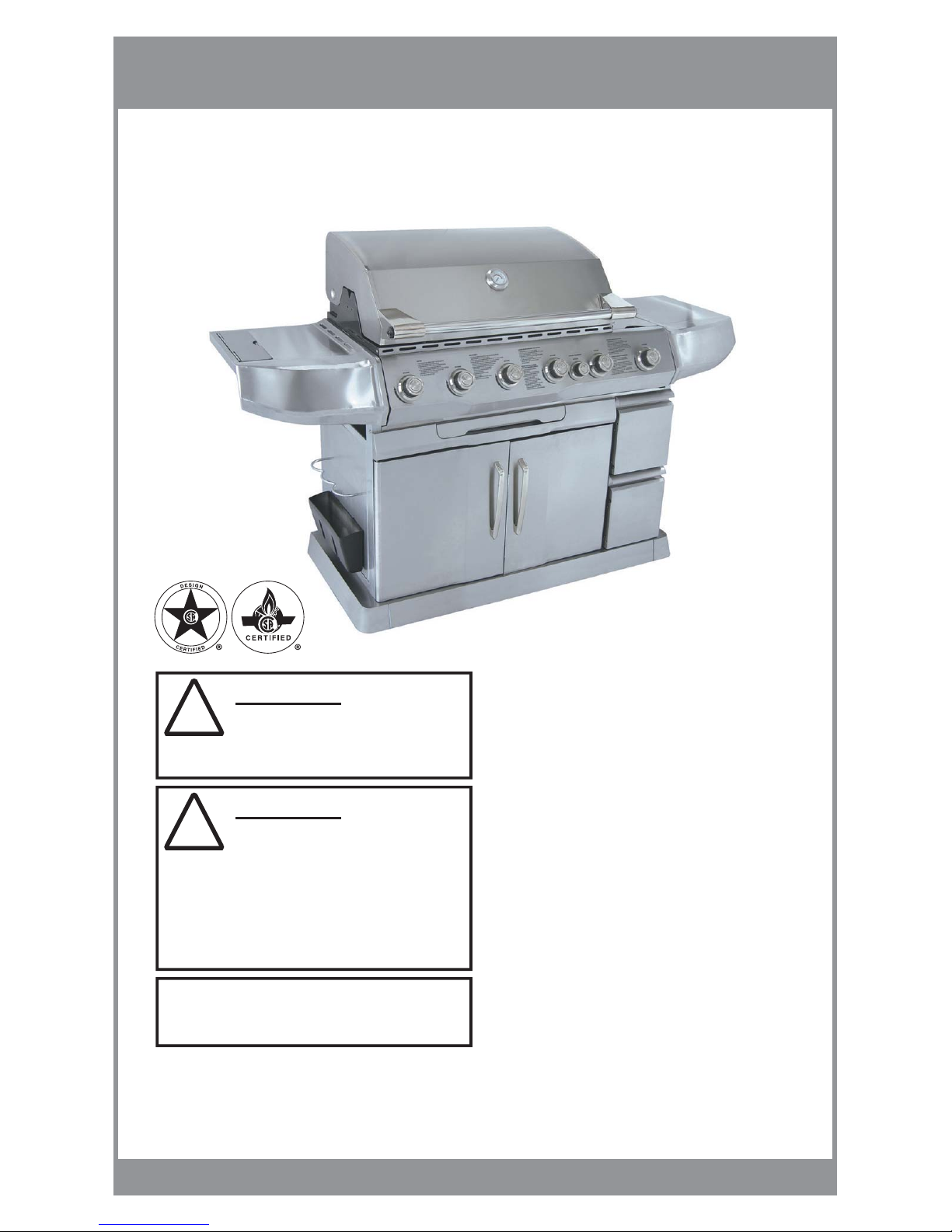
82,500 BTU OUTDOOR GAS GRILL
OWNERS / ASSEMBLY MANUAL
Phoenix Innovations Corp.
103-1540 Cornwall Rd. Oakville, ON Canada L6J 7W5
Made in China / Printed in China
Save these instructions for future reference. If you are
assembling this unit for someone else, give this manual to
him or her to read and save for future reference.
!
WARNING
For Your Safety:
1. Improper installation, adjustment, alteration, service
or maintenance can cause injury or property damage.
2. Read the installation, operation, and maintenance
instructions thoroughly before installing, using or
servicing this appliance.
3. Failure to follow these instructions could result in
fire or explosion, which could cause property damage,
personal injury, or death.
California Proposition 65:
Chemicals known to the State of California to cause
cancer, birth defects, or other reproductive harm are
created by the combustion of propane.
!
WARNING
For Your Safety:
For Outdoor Use Only
(do not use under any overhead enclosure)
Table of Contents
Use of the Appliance 1
Parts / Hardware List 2
Assembly Instructions 3
Use of Electrical Accessories 9
Lighting / Operating Instructions 10
Retractable Grill Light 10
Infrared Rear Burner 11
LP Gas Supply 12
LP Gas Cylinder 12
Hose and Regulator Assembly 13
Natural Gas Supply Connection 14
Leak Test 14
Maintenance 15
Cleaning and Care
Cooking Grids
Heat Plates
Grease Cup/drawer
Bottom Bucket
Exterior Surfaces
Grilling Tips 16
Cooking Guides 17
Trouble Shooting 19
Warranty 20
For Models:
PH603SB
PH603SBN
L0019 - Rev. 12/06
Page 2
PAGE # 1
Call 1-877-744-3649 for assistance or visit us at www.phoenixinno.com
For Models:
PH603SB
PH603SBN
OWNERS MANUAL
!
DANGER
For Your Safety:
If you smell gas:
1. Shut off gas to the appliance.
2. Extinguish any open flame.
3. Open lid.
4. If odor continues, keep away from the appliance and
immediately call your gas supplier or your fire department.
!
WARNING
For Your Safety:
1. Do not store or use gasoline or other flammable
liquids or vapors in the vicinity of this or any
other appliance
2. An LP cylinder not connected for use shall not be
stored in the vicinity of this or any other appliance.
Your new Life @ Home™ gas BBQ grill is a safe and enjoyable cooking appliance when assembled
and used properly. Certain safeguards must be followed in order to ensure safety. Failure to follow
these safeguards may result in damage or injury. If you have any questions about the assembly or
use of this appliance, please call our toll-free customer service line at 1-877-744-3649.
USE OF THIS APPLIANCE
1. This appliance must be installed in accordance with the latest local codes. In the absence of local codes, use the:
United States - National Fuel Gas Code, ANSI Z223.1/NFPA 54
- LP-Gas Code, NFPA 58
Canada - Natural Gas and Propane Installation Code, CSA B149.1
- Propane Storage and Handling Code, CSA B149.2
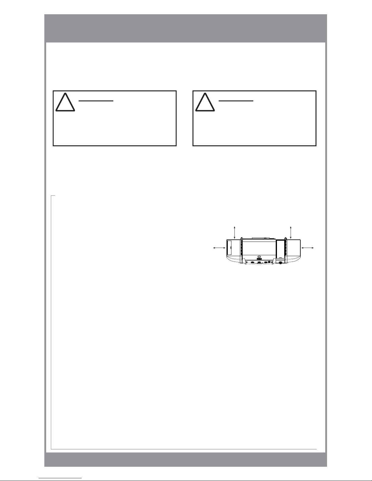
2. This appliance must be located away from combustible surfaces by no less than
30” (76 cm) from either of the sides or back of the appliance. See Fig. A
3. This appliance is for outdoor use only, and shall not be used in a building,
garage, shed, balcony, or any other enclosed area.
DO NOT operate this appliance under any overhead roof construction or foliage.
4. DO NOT restrict the flow of combustion and ventilation of air to this appliance.
5. Keep the ventilation openings of the cylinder enclosure free and clear from debris.
6. DO NOT use or install this appliance in or on boats or recreational vehicles.
7. Keep the area surrounding this appliance free of combustible materials, gasoline, and all other flammable liquids and vapors.
8. This appliance is not intended for commercial use.
9. The use of alcohol, prescription or non-prescription drugs may impair the user’s ability to properly assemble or safely operate this appliance.
10. Do not alter this appliance in any manner.
11. Do not use this appliance unless it is fully and properly assembled and all parts are securely fastened.
12. When cooking, fire extinguishing materials shall be readily accessible. In the event of a grease fire, do not attempt to extinguish with water.
Use type BC dry chemical fire extinguisher or smother with dirt, sand or baking soda. Turn off LP gas cylinder or NG supply valve immediately
to stop the flow of gas.
13. Do not leave the appliance unattended while in use. Take special care to keep children and pets away from the appliance at all times.
14. Do not attempt to move the appliance while in use.
15. Always place this appliance on a hard, non-combustible, level surface.
16. Never use this appliance indoors. Toxic fumes can accumulate.
17. Always turn off gas at the LP gas cylinder or NG supply valve when the appliance is not in use.
18. a. The outdoor cooking gas appliance and its individual shutoff valve must be disconnected from the gas supply piping system
during any pressure testing of that system at test pressures in excess of 0.5 psi (3.5 kPa.)
b. The outdoor cooking gas appliance must be isolated from the gas supply piping system by closing its individual manual shutoff valve
during any pressure testing of the gas supply piping system at test pressures equal to or less than 0.5 psi (3.5 kPa.)
PRIOR TO USE:
1. Prior to using the appliance for the first time:
a. Remove cooking grids, warming rack, and heat plates. Wash with mild soap and water.
b. Light main burners set to “Medium” setting and let burn for 20 min. with the lid down. This will help to burn off any odors or foreign matter.
c. Turn off gas at the LP gas cylinder service valve or NG supply valve and let appliance cool. Replace cooking grids, warming rack and heat plates.
2. Prior to using the appliance each time:
a. Light the appliance main burners and let pre-heat for 5-10 minutes
30” (76 cm)
30” (76 cm)30” (76 cm)
Fig. A
Page 3
PAGE # 2
Call 1-877-744-3649 for assistance or visit us at www.phoenixinno.com
PARTS / HARDWARE LIST
(Please identify all parts / hardware before beginning assembly)
PART # DRAWING
A Cabinet Frame
B Rear Locking Castors (2)
C Front Non-Locking Castors (2)
D Front Skirt Trim Piece
E Left Skirt Trim Piece
F Right Skirt Trim Piece
G Right Side Panel
H Center Panel
I Left Side Panel
J Tool Caddy Door
K Tool Caddy Bucket
L Tool Caddy Wire Support
M Back Panel
N Wire Shelf (inside bottom cabinet)
O Tank Support Wire
(not required/supplied for
Natural Gas model PH603SBN)
P-L / P-R Grease Tray Support Bars (2)
Q Horizontal Front Panel
R Grease Tray
S BBQ Grill Head
T Left Side Shelf Top
U Left Side Shelf Front
V Removable Condiment Holder
W Right Side Shelf Top
X Right Side Shelf Front
Y Right Door
Z Left Door
Medium washer
Medium
washer
PART # DRAWING
A-1 Grease Tray face
B-1 Drawer Face (2)
C-1 Drawer Bucket (2)
D-1 Drawer Rails (2)
E-1 Heat Tent (5)
F-1 Cooking Grids (5)
G-1 Rotisserie Kit
PART # DRAWING
H-1 Warming Rack
I-1 Side Burner Grate
J-1 Side Burner
K-1 Match Stick holder
L-1 Tank Support Wire Bracket
(not required/supplied for
Natural Gas model PH603SBN)
M-1 Skirt Trim Mounting Brackets (4)
N-1 Drip Tray
For Models:
PH603SB
PH603SBN
J-1
H-1
I-1
G-1
F-1
E-1
D-1
D-1
C-1
C-1
B-1
B-1
A-1
K-1
L-1
A
B
B
C
C
D
E
F
G
I
H
K
O
P-RP-L
M
L
J
N
N-1
T
V
X
Y
Z
R
Q
S
U
W
Small
philips head bolt
M4 x 12
Medium
philips head bolt
M6 x 15
Large
philips head bolt
M6 x 45
4
57
2
PART # DRAWING DESCRIPTION QTY
1
2
3
8
8
2
PART # DRAWING DESCRIPTION QTY
Large washer
Large wing nut
Large
washer
Large
wing nut
Hardware List
Tools Required
Philips Screwdriver (Included)
Natural Gas Hose
supplied for Natural Gas model
PH503SBBN only
M- 1
M- 1
M- 1
Page 4
PAGE # 3
Call 1-877-744-3649 for assistance or visit us at www.phoenixinno.com
STEP 1: Identify parts & hardware
1. Unpack and identify all parts and hardware pack using the parts list and hardware list provided in this manual.
2. If you are missing any parts, PLEASE DO NOT RETURN THIS PRODUCT TO STORE.
3. For assistance please call our Customer Service hotline at 1-877-744-3649.
ASSEMBLY INSTRUCTIONS:
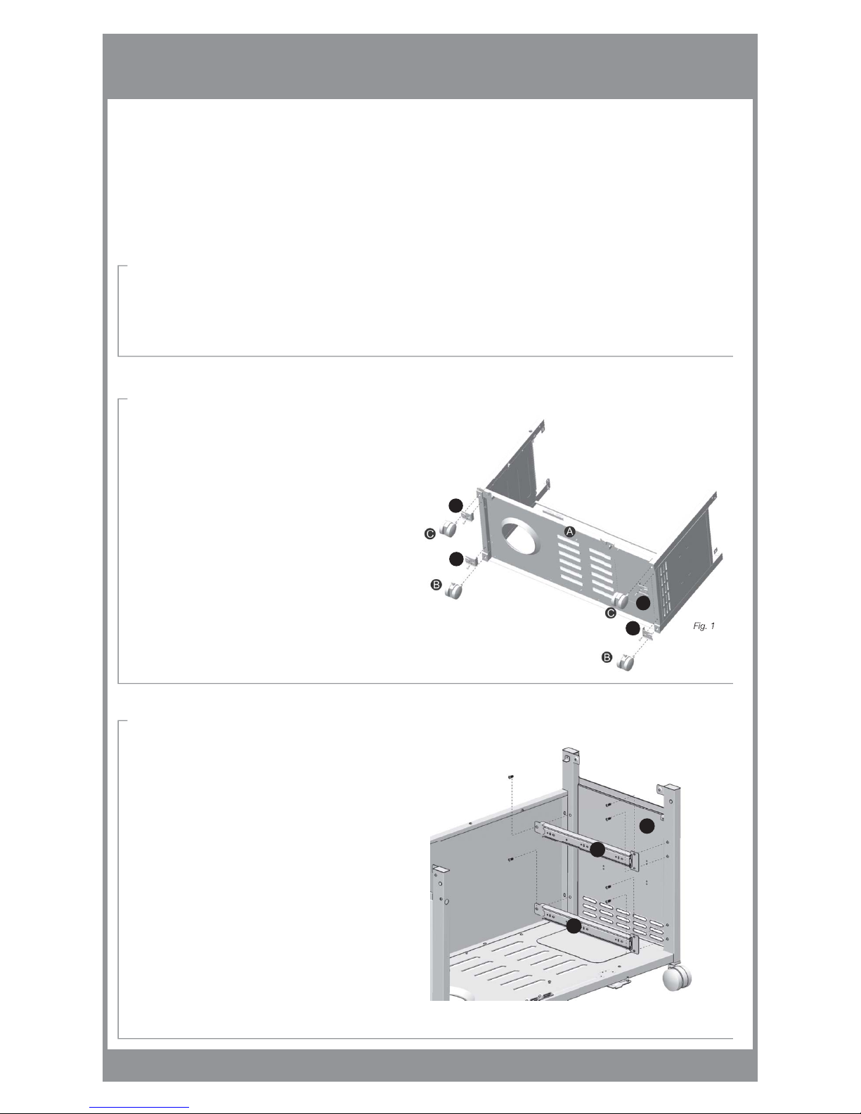
STEP 2: Attach skirt brackets & castors
NOTE: PLACE ON CARDBOARD OR CLOTH
TO PROTECT PAINT/STEEL FINISH.
1. Attach skirt trim mounting brackets (M-1) to cabinet frame (A)
using 4 medium bolts.
2. Insert 2 rear locking castors (B) into bottom of rear leg posts.
3. Insert 2 front non-locking castors (C) into bottom of front leg posts.
NOTE: LOCK REAR CASTORS TO PREVENT CABINET
FROM MOVING DURING ASSEMBLY.
STEP 3: Attach drawer rails
1. Attach top and bottom drawer rails (D-1) to right side panel (G)
of the grill cabinet using 6 medium bolts.
Fig. 1
Fig. 2
For Models:
PH603SB
PH603SBN
D-1
D-1
G
M- 1
M- 1
M- 1
M- 1
Page 5
PAGE # 4
Call 1-877-744-3649 for assistance or visit us at www.phoenixinno.com
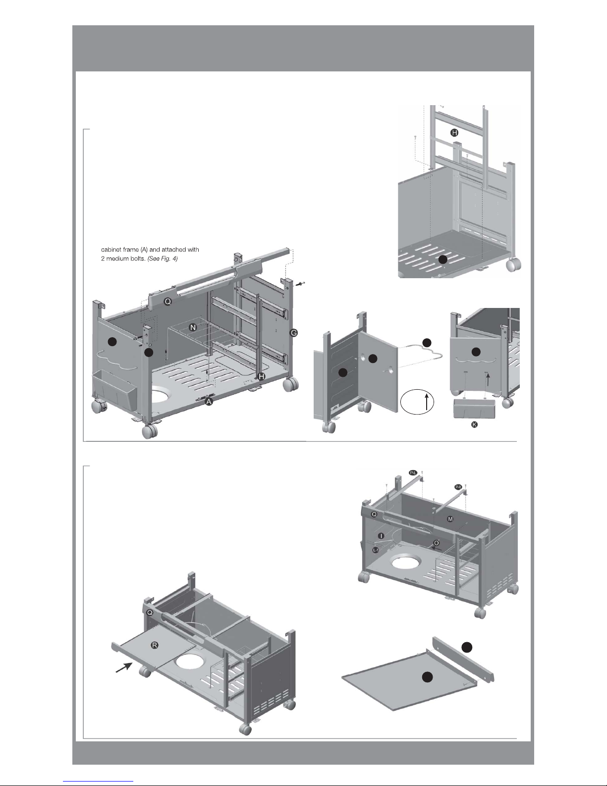
STEP 4: Assemble cabinet frame
1.
Secure center panel (H) inside the cabinet frame by using 3 medium bolts. (See Fig. 3)
2. Attach horizontal front panel (Q) to right side panel (G) by securing 1 large bolt and medium washer. Also
secure horizontal front panel (Q) to left side panel (I) with 1 large bolt and medium washer and
1 medium bolt. Further secure front panel (Q) to
center panel
(H) with 1 medium bolt.
(See Fig. 4)
3. Insert tool caddy wire support (L) through the tool caddy door (J) and tighten with 2 wing nuts.
(See Fig. 4.1)
4. Insert tabs on tool caddy bucket (K) into slots in tool caddy door (J).
(See Fig. 4.2)
Note:
The tool caddy bucket can be stored when not in use on the inside of the left cabinet door (Z).
5. Attach the wire shelf (N) by inserting into 2 existing holes located on center panel (H).
Extend the legs of the shelf, align into position over the 2 existing holes located on the
cabinet frame (A) and attached with
2 medium bolts.
(See Fig. 4)
STEP 5: Complete cabinet
1. Secure left (P-L) and right (P-R) grease tray support bars to horizontal front panel (Q) and
back panel (M) with 4 medium bolts. (See Fig. 5)
2. Insert end of tank support wire (O) into the back of the left side panel (I) and secure other
end of tank support wire by fastening in place with tank support wire bracket (L-1) with
2 medium bolts. (The tank support wire (O) and the tank support wire bracket (L-1) are not
required / not supplied for Natural Gas Model PH603SBN).
3. Attach grease tray face (A-1) to the main grease tray (R) with 2 medium bolts. (See Fig. 6)
4. Insert grease tray (R) into horizontal front panel (Q). (See Fig. 6.1)
For Models:
PH603SB
PH603SBN
Fig. 3
Fig. 5
Fig. 6.1
Fig. 6
R
A-1
A
J
L
I
J
Fig. 4
J
I
Fig. 4.1
Fig. 4.2
LIFT TO
CLOSE
DOOR.
Page 6
PAGE # 5
Call 1-877-744-3649 for assistance or visit us at www.phoenixinno.com
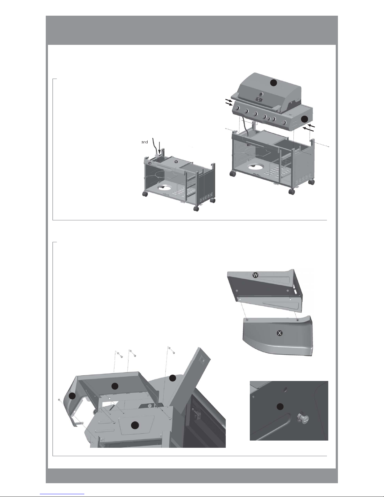
STEP 6: Assemble
BBQ grill head
1. Note: 2 people are required for this step.
2. Rest BBQ grill head (S) onto cabinet frame. Ensure that the hose and regulator
(or natural gas hose assembly for Model PH603SBN) sits inside the cabinet. (See Fig. 7)
Ensure that the holes in the grill head line up with the “L” brackets extending
from the cart frame legs. (See Fig. 7.1)
3. Insert 4 medium bolts through “L” brackets and
into BBQ grill head (S).
STEP 7: Attach right side shelf
NOTE: PLACE ON CARDBOARD OR CLOTH
TO PROTECT PAINT/STEEL FINISH.
1. Insert 2 medium bolts through right side shelf top (W) into
right side shelf front (X) and tighten.
(See Fig. 8)
2. Loosen 2 bottom bolts already installed in the side burner (J-1).
DO NOT REMOVE.
(See Fig. 8.1)
3. Place right side shelf onto the side burner (J-1) by lining up 2 bottom
keyholes in right side shelf (W & X) with 2 bolts loosened from the side burner (J-1).
Lower the side shelf into place.
(See Fig. 9)
DO NOT TIGHTEN BOLTS.
4. From the inside of the side burner (J-I), use 3 medium bolts and large
washers to secure
assembled side shelf.
Tighten once in place.
(See Fig. 9)
5. Tighten the 2 bottom bolts from steps 2 and 3.
6. Secure right side shelf front (W) to BBQ grill head (S) with 1 medium bolt.
(See Fig. 9)
For Models:
PH603SB
PH603SBN
Fig. 7.1
Fig. 7
Fig. 8
Fig. 8.1
Fig. 9
W
X
LIFT
FROM
HERE
LIFT
FROM
HERE
S
J-1
J-1
J-1
S
Page 7

PAGE # 6
Call 1-877-744-3649 for assistance or visit us at www.phoenixinno.com
STEP 9: Assemble drawers
1. Attach drawer face (B-1) to drawer bucket (C-1) using 4 medium bolts and
medium washers. Repeat for second drawer. (See Fig. 12)
2. Extend the drawer rails (D-1) (installed in step 3).
3. Insert bracket on drawer bucket (C-1) into drawer rails (D-1).
Push drawer closed to lock in place.
(See Fig. 12.1)
Fig. 12.1Fig. 12
For Models:
PH603SB
PH603SBN
STEP 8: Attach left side shelf
NOTE: PLACE ON CARDBOARD OR CLOTH
TO PROTECT PAINT/STEEL FINISH.
1. Insert 2 medium bolts through left side shelf top (T) into left side shelf front (U) and tighten.
(See Fig. 10)
2. Loosen 2 bottom bolts already installed in the BBQ grill head (S). DO NOT REMOVE.
(See Fig. 11)
3. Place left side shelf onto left side of BBQ grill head (S) by lining up 2 bottom keyholes
in left side shelf (T & U) with 2 bolts loosened from BBQ grill head (S). Lower the
side shelf into place.
(See Fig. 11.1)
DO NOT TIGHTEN BOLTS.
4. From the inside of the BBQ grill head (S), use 3 medium bolts and large
washers
to secure assembled side shelf. Tighten once in place.
5. Tighten the 2 bottom bolts from steps 2 and 3.
6. Secure left side shelf front (U) to BBQ grill head (S) with 1 medium bolt.
(See Fig. 11.1)
7. Place removable condiment holder (V) into left side shelf top (T).
(See Fig. 10)
Fig. 11.1
Fig. 10
Fig. 11
S
T
U
Page 8

PAGE # 7
Call 1-877-744-3649 for assistance or visit us at www.phoenixinno.com
STEP 11: Attach doors
1. Place right door (Y) over the bottom hinge pin on the
front skirt trim piece (D) so the pin enters the pre-drilled hole
in the door’s bottom. Push up the top hinge pin located in
bottom of the horizontal front panel (Q) and lock into the
pre-drilled hole in right door (Y). (See Fig. 15).
2. Place left door (Z) over the bottom hinge pin on front
skirt trim piece (D) so the pin enters the pre-drilled hole
in the door’s bottom. Push up the top hinge pin located
in bottom of the horizontal front panel (Q) and lock into the
pre-drilled hole in left door (Z). (See Fig. 15).
STEP 10: Attach bottom trim
NOTE: PLACE ON CARDBOARD OR CLOTH
TO PROTECT PAINT/STEEL FINISH.
1. Assemble right (F), left (E) and front (D) skirt trim pieces using
4 #1 bolts. (See Fig. 13)
2. Align and slide the assembled skirt onto the grill from the front.
Attach to skirt mounting brackets (M-1) with 6
medium bolts.
(See Fig. 14)
For Models:
PH603SB
PH603SBN
Fig. 13
D
E
F
Fig. 14
Fig. 15
M- 1
M- 1
Z
Page 9

PAGE # 8
Call 1-877-744-3649 for assistance or visit us at www.phoenixinno.com
STEP 13: Attach gas supply
FOR PROPANE MODELS:
1. Lift tank support wire (O) and position LP gas cylinder in the opening
on bottom panel. (See Fig. 17)
2. Lower tank support wire (O) over the LP gas cylinder collar and secure. (See Fig. 18)
3. Attach regulator to LP tank (see “LP Gas Cylinder” section of this manual
for proper assembly instructions).
FOR NATURAL GAS MODELS:
1. Feed the natural gas hose through the opening of the back panel (M). (See Fig. 19)
2. Attach the hose of the appliance to your natural gas supply.
3. Refer to “Natural Gas Supply Connection” section of this manual
for proper assembly instructions).”
STEP 12: Install cooking
components
1. Place heat tents (E-1) into slots located in front of grill head (S)
and lower over each burner.
2. Insert cooking grids (F-1), warming rack (H-1) and side burner grate (I-1)
3. From behind the grill, install the drip tray (N-1) by sliding it into place onto the
2 channels located on the bottom of the grill head (S). (See Fig 16.1)
4. For battery installation in each grill light,
refer to Page 10, Fig. 3 & 4.
For Models:
PH603SB
PH603SBN
Fig. 16Fig. 16.1
Fig. 17
Fig. 18 Fig. 19
N-1
M
Page 10

PAGE # 9
Call 1-877-744-3649 for assistance or visit us at www.phoenixinno.com
USE OF ELECTRICAL ACCESSORIES
1. If an accessory is used on this appliance that requires an external electrical power source, the accessory when installed must be electrically
grounded in accordance with local codes. In the absence of local codes, use the:
United States: National Electrical Code, ANSI/NFPA 70
Canada: Canadian Electrical Code, CSA C22.1
2. The accessory should be equipped with a 3 prong (grounding) plug for your protection against shock hazard and should be plugged directly
into a properly grounded three-prong receptacle. Do not cut or remove the grounding prong from this plug.
3. Keep any electrical supply cord and the fuel supply hose away from any heated surface.
LIGHTING INSTRUCTIONS
A Main burner control knobs
B Lid
C Lid handle
D Rotisserie burner control knob
E Side burner control knob
F LP tank
G Lighting hole
H Cylinder valve
I Grill Light
J Match Stick
1. Ensure the appliance is assembled in accordance with the manufacturers instructions.
2. Ensure that the LP gas cylinder or NG supply is properly connected and full (for LP models).
3. Inspect the hose before each use. If evidence of abrasion, wear, cuts or any other
damage exists, replace the hose before using the appliance.
Use only replacement parts from Phoenix Innovations Corp.
4. Ensure that there are no gas leaks. See “Leak Test” section of this manual.
5. Ensure that the venturi tubes/burners are properly aligned on the burner control valve orifices. (See Fig. 1)
6. Ensure that the main, side and rotisserie ignitor wires are properly connected.
7. Read and understand all instructions as they pertain to this appliance before lighting.
8. Open the lid and make sure the burner control knobs are in the “OFF” position.
9. Slowly open LP gas cylinder service valve or NG suppy valve.
10. MAIN AND SIDE BURNER(S): Push and turn desired burner control knob(s) to the “HIGH” position.
The ignitor will light the burner.
ROTISSERIE BURNER: Push in, turn and hold control knob to “HIGH” position for approximately 10 sec. to activate the saftey valve.
Once burner is lit, position the control knob to desired setting and release control knob. If ignition does not occur within 5 sec.,
or burner goes out, turn burner control knob(s) “OFF”, wait 5 min. and repeat lighting procedure.
11. If ignition does not occur within 5 sec., turn burner control knob(s) “OFF”, wait 5 minutes and repeat
lighting procedure. If any burner will not light, refer to the “Trouble Shooting” section of this manual.
If the problem can not be resolved, contact our customer service department at 1-877-744-3649, www.phoenixinno.com or
a licensed gas technician before using the appliance.
12. Do not operate the main and rotisserie burners at the same time.
13. When on “HIGH” position, the main burners should provide a 1” (2.5 cm) flame. (See Fig. 2-1)
For Models:
PH603SB
PH603SBN
1” (2.5 cm) flame
Fig. 2-1
Tube Burner
Valve orifice
1/4”
Fig. 1
Tube Burner
Valve orifice
✓
✓
✘
Page 11

PAGE # 10
Call 1-877-744-3649 for assistance or visit us at www.phoenixinno.com
LIGHTING INSTRUCTIONS
BURNER AIR SHUTTER ADJUSTMENT
If main or side burner flame is not as indicated in Fig. 2-1, adjust the air shutters to improve flame.
To adjust air shutters:
1. Light burners.
2. Loosen retaining screw slightly and rotate air shutter with a pair of needlenose pliers. (See Fig. 2-2)
(this will increase or restrict air flow to the burners)
3. Once flame is acceptable, re-tighten retaining screw.
MANUAL LIGHTING
If the ignitor does not light the burner(s), use a lit match (secured onto the match stick (K-1) provided inside right door)
to light burners manually. Access the burners through the cooking grids and heat plates.
Position the lit match near the side of the burner while pushing and turning closest burner
control knob to the “HIGH” position. (See Fig. 2-3) The burner should ignite within 5 seconds.
Push and turn other burner control knobs to the “HIGH” position.
If burner does not light within 5 sec., turn off all control knobs and gas supply, wait 5 minutes and repeat.
NOTE: Always use the match stick provided when lighting burners with a match.
After lighting, observe the burner flame, make sure all burners are lit and flame height matches
illustration. (See Fig. 2-1)
NOTES:
1. To light side or rotisserie burners with a match or butane lighter, position the flame close to the
burner and repeat steps above. Do not operate the main and rotisserie burners at the same time.
2. When using the rotisserie burner, remove warming rack.
3. Always check the burner to confirm that ignition has occurred.
SHUT DOWN:
1. Close the LP gas cylinder or NG valve.
2. Turn all burner control knobs to the “OFF” position.
Fig. 4
RETRACTABLE GRILL LIGHTS
Your grill comes equipped with two retractable grill lights to assist you while you grill in low light situations.
The grill lights are stored convienently in either side of the grill handle.
To extend the gill lights, simply pull the grill light out from inside the grill lid handles.
Press the button at the end of the grill light to turn off/on. The flexible shaft allows you to aim the light
exactly where you need it.
To retract the lights, simply straghten the flexible shaft horizontal to the grill handle,
push and guide the light in until the light cap is flush with the grill handle cap.
INSTALLING / REPLACING BATTERIES
Your grill light uses 3 AAA alkaline batteries (included). To install/replace the batteries,
1. Unclip and remove battery cap from light head. (See Fig. 4)
2. Remove old batteries and replace with new.
3. Reattach battery cap to light head securely.
Fig. 3
For Models:
PH603SB
PH603SBN
Fig. 2-3
Fig. 2-2
Rotate
Page 12

PAGE # 11
Call 1-877-744-3649 for assistance or visit us at www.phoenixinno.com
7
Fig. 7
Fig. 8
Fig. 9
Fig. 10 Fig. 11
Fig. 6.1
Fig. 6
For Models:
PH603SB
PH603SBN
INFRARED ROTISSERIE BURNER
Your grill comes equipped with an infrared burner and a rotisserie kit for rotisserie cooking. The infrared rotisserie burner is great for cooking
roasts and fowl (Max 15 lbs / 6.8 kg). With the heat source located behind the food, there is no chance of a flare up caused by fat dripping
on to hot burners below to burn or spoil your meal. A dish or drip pan placed below the spit will collect the juices for basting or for preparing a sauce.
NOTE: READ ALL INSTRUCTIONS
1. DO NOT operate rotisserie with a damaged cord or plug, or if the rotisserie malfunctions or has been damaged in any way.
2. DO NOT let children operate grill or rotisserie, and DO NOT let children play nearby.
3. Unplug rotisserie motor from electrical outlet when not in use and before cleaning. Allow to cool before adding or removing parts.
4. To protect against electrical shock, DO NOT immerse electrical cord, plug or motor in water or expose to rain or snow. Protect electrical elements.
5. Most grill surfaces and accessories become hot during and after cooking, so use reasonable care and caution around grill.
Wear flame retardant BBQ mitts when handling the rotisserie.
6. This rotisserie is for outdoor use only.
To operate your rear burner see lighting instructions on page 9.
HOW TO USE / INSTALL YOUR ROTISSERIE KIT
Your rotisserie kit includes the following:
1. Motor
2. 4 prong meat forks with locking wing bolts (2)
3. Spit rod
4. Motor support bracket
5. Motor support extension
6. Counter balance with locking wing bolt
7. Spit collar
INSTALL MOTOR BRACKET
1. Line up holes in motor support bracket (part #4) with holes in grill head and attach securely
using the 2 medium bolts included with your rotisserie kit. (See Fig 6)
2. Slide the motor support extension (part #5) over the motor support bracket (part #4).
3. Slide motor (part #1) onto motor support extension (part #5).
POULTRY
1. With breast down, bring neck skin up over cavity.
Fold under edges of skin, skewer to keep in place. (See Fig 7)
2. Turn breast side up, tie wings to body with twine. (See Fig 8)
3. Slide a meat fork on spit rod and tighten. Insert the spit rod in neck skin parallel
to the backbone, bring it out just above the tail. (See Fig 9)
4. Insert second meat fork on opposite side of spit rod and secure. Make sure the bird is
centered on the spit rod. Tighten wing bolts securely on meat forks. (See Fig 10)
5. Cross the legs to tail and tie to the spit rod with twine. (See Fig 11)
6. Rest spit rod onto grooves in left and right side of grill head. Allow the spit rod to rotate freely so that the heaviest part of the poultry/meat is facing down.
7. Add the counterbalance so that it’s weight is directly opposite of the heaviest part of the poultry/meat (i.e. it will be facing straight up at this point).
Tighten the counter balance in position by turning the axel. Fine adjustments can be made by sliding the weight up and down the axel and securing it
with the thumb screw. (See Fig 6.1) Note: Position the counter balance so it does not interfere with the side bucket.
8. Insert the pointed end of the spit rod into motor.
9. Attach spit collar to the other end of the spit rod and position into the groove on right side of grill head.
FOR COOKING TIMES AND TEMPERATURES SEE COOKING GUIDES ON PAGE #18
Page 13

PAGE # 12
Call 1-877-744-3649 for assistance or visit us at www.phoenixinno.com
LIQUID PROPANE (LP) GAS SUPPLY (FOR LP MODLES ONLY)
1. This appliance is for use with LP gas only. The conversion to or attempted use of natural gas (NG) in this appliance is dangerous and
will void your warranty.
2. LP Gas:
a. Is explosive under pressure
b. Is heavier than air and thus settles in low areas
c. Is extremely flammable and hazardous if handled improperly
d. Has no natural odor. An odorant has been added to notify you of any potential leaks.
e. Can cause freeze burns when in contact with skin
LP GAS CYLINDER (FOR LP MODLES ONLY)
1. A LP gas cylinder is required to operate this appliance. The LP gas cylinder is not included
with this appliance.
2. Be sure to use only 1 20 lb (9.1 kg) LP gas cylinder with a Type 1 valve with this appliance as required
by the American National Standards Institute (ANSI) and the Canadian Standards Steering Committee.
3. LP gas cylinders must:
a. Be marked “propane”.
b. Be constructed and marked in accordance with the Specifications for LP Gas Cylinders of the U.S. Department of Transportation
(D.O.T.) or the National Standards of Canada, CAN/CSA-B339, Cylinders, Spheres and Tubes for Transportation of Dangerous Goods;
and Commission, as applicable.
c. Not have a capacity larger than 20 lbs (9.1 kg) with approximate dimensions of 18” (45.7 cm) high and 12” (30.4 cm) diameter.
d. Be inspected at each re-filling and re-qualified by a licensed professional upon expiry (10 years from date of manufacture),
in accordance with local and/or national codes for LP gas cylinders.
e. Contain a shut-off valve as specified in the Standard for Compressed Gas Cylinder Valve Outlet
and Inlet Connection, ANSI/CGA-V-1-1977, CSA B96.
f. Be arranged for vapor withdrawal. LP tank must be in upright position.
g. Include a collar to protect the cylinder valve.
h. Be installed as per assembly instructions for the appliance.
i. Include a safety relief device having direct communication with the vapor space of the cylinder at all times.
j. Have a listed overfilling protection device (OPD)
k. Be provided with a cylinder connection device compatible with the connection for outdoor cooking appliances.
4. Never attempt to attach this appliance to the self-contained LP gas system of a camper trailer, motor home or house.
5. Special care should be taken to avoid dropping or rough handling of the LP gas cylinder. Never use a LP gas cylinder with a
damaged body, valve, collar or footing.
6. LP gas cylinders should be filled only by a certified LP gas dealer.
7. Always transport filled LP gas cylinders carefully, securely and in the upright position. Special care should be given to protect the valve
from accidental damage.
8. Keep the LP gas cylinder in the upright position when connecting it to the appliance and secure to the appliance.
9. If the LP gas cylinder is tipped after connection to the appliance, shut off the cylinder service valve, disconnect the regulator from the cylinder,
and have the cylinder and regulator inspected prior to use.
10. LP gas cylinders must be stored outdoors in a well-ventilated area, out of the reach of children and must not be stored in a building,
garage or any other enclosed area.
11. a. Do not store a spare LP gas cylinder under or near this appliance.
b. Never fill the LP gas cylinder beyond 80% full.
c. If the information in 11(a) and 11(b) is not followed exactly, a fire causing death or serious injury may occur.
12. Do not store the LP gas cylinder in direct sunlight or near a source of heat or combustion.
Never store a cylinder where temperatures can reach over 50°C / 125°F. Never keep a filled LP gas cylinder in a hot car or car trunk.
13. If storing the grill indoors, the LP gas cylinder must be disconnected, removed and stored outside.
14. Place a dust cap on the cylinder service valve outlet whenever the cylinder is not in use. Only install the type of dust cap on the
cylinder service valve outlet that is provided with the cylinder valve. The use of other types of dust caps or plugs may result in leakage
of propane from the cylinder service valve. To disconnect the LP gas cylinder, ensure that the LP cylinder service valve is shut off and then
turn the regulator hand wheel counter clockwise.
15. When the LP gas cylinder is connected to the appliance, the appliance and the LP gas cylinder must be stored outside in a well ventilated area.
S
P
E
C
I
F
I
C
A
T
I
O
N
S
H
A
N
D
L
E
I
N
G
S
T
O
R
A
G
E
O
f
f
C
l
o
c
k
w
i
s
e
Safety
Relief Valve
Cylinder Service
Valv e
Type1 Outlet with
thread on outside
Strap and Dust Cap
For Models:
PH603SB
PH603SBN
Page 14

PAGE # 13
Call 1-877-744-3649 for assistance or visit us at www.phoenixinno.com
LP GAS CYLINDER (FOR LP MODELS ONLY)
16. Always use the pressure regulator and hose assembly provided with the appliance to connect to a LP gas cylinder.
Never connect to an unregulated LP gas supply. Contact our customer service department for replacement parts at
1-877-744-3649 or www.phoenixinno.com.
17. When connecting the LP gas cylinder to the appliance, always test for gas leaks.
See “Leak Test” section of this manual.
18. If you smell gas, do not use the appliance until the source of the leak has been
detected and repaired .
19. Always shut off the LP gas cylinder service valve as well as the burner control valves
when the appliance is not in use.
20. Be sure the LP gas cylinder service valve and burner control valve(s) are “OFF”.
21. Set a full LP gas cylinder into the well located on the bottom of the appliance and secure in place.
22. Center the probe of the appliance side connection in the cylinder service valve outlet and hold in place.
With your other hand, turn the plastic nut clockwise until fully engaged on the cylinder service valve
ACME thread. (See Fig. 13) DO NOT USE TOOLS. HAND TIGHTEN ONLY.
23. Perform the leak test (see “Leak Test” section of this manual) on all connections.
24. When lighting the grill, follow the lighting instructions as stated in this manual.
Always open the LP gas cylinder service valve before opening the burner control valve(s)
to avoid activating the flow limiting device. See “Hose and Regulator Assembly” section
of this manual for more details of the flow limiting device.
HOSE & REGULATOR ASSEMBLY (FOR LP MODELS ONLY)
1. All models come equipped with a standard LP gas hose and regulator including the
appliance side connection for a CGA No 791 Cylinder Connection Device .
a. The CGA No 791 connection incorporates a magnetic flow limiting device that
acts to limit the flow of gas if a leak is detected between the regulator and
the burner valve(s).
b. If the burner valve(s) is open prior to the LP gas cylinder service valve being
opened, the connection will interpret this free flow of gas to be a leak.
c. The connections safety feature will reduce gas flow from the regulator to
the appliance to a minimal level.
d. Be sure that all burner valves are closed prior to opening the LP gas cylinder
service valve to ensure that the connection flow limiting device is not triggered mistakenly.
e. If the connection flow limiting device is triggered mistakenly, close the LP gas cylinder
service valve and the burner valves, wait 10 seconds to allow the device to reset, open the cylinder service valve,
then open the burner valves and light the grill as per lighting instructions.
2. Be sure to protect the hose from dripping grease and any hot surfaces – including the base of the appliance.
Serious danger may result if the hose contacts any hot surface.
3. Regular maintenance of the hose and regulator:
a. Inspect the hose before each use of the appliance. If the hose shows signs of cracks, abrasions,
cuts or damage of any kind, do not operate the appliance. Fix or replace the hose as required before using the appliance.
For assistance with repair or replacement of the hose, call our customer service line at
1-877-744-3649 or www.phoenixinno.com. Use only replacement parts from Phoenix Innovations Corp.
b. Inspect the seal inside the CGA No 791 service valve on the LP gas cylinder when replacing the cylinder or at least
once per year. If there is any indication of damage, have the seal replaced by a certified gas dealer before operating the appliance.
4. Do not use tools to tighten the CGA No 791 connection nut onto the LP gas cylinder service valve – hand tighten only.
5. Be sure not to cross thread the connection when tightening the CGA No 791 connection on to the LP gas cylinder service valve.
6. Always perform the “leak test” (see leak test section) after attaching the connection to the LP gas cylinder service valve.
O
P
E
R
A
T
I
O
N
C
O
N
N
E
C
T
I
O
N
Cylinder
Hand Wheel
Cylinder
Service Valve
Straight
Fig. 13
For Models:
PH603SB
PH603SBN
Regulator
Nipple has to be centered
into the LP cylinder service valve.
Fig. 14
Hose
Regulator
Fig. 12
Page 15

PAGE # 14
Call 1-877-744-3649 for assistance or visit us at www.phoenixinno.com
LEAK TEST
1. All factory-made connections of the hose and regulator have been thoroughly tested to ensure no gas leaks are present.
However, through shipping and handling, certain gas connections may have loosened. As a safety precaution:
a. Check all connections for gas leaks before using the appliance
b. Check for gas leaks at the LP cylinder valve after each time the cylinder is replaced or at the
NG supply valve any time the fitting is reconnected.
c. Do not smoke while checking for gas leaks or anytime you are in the vicinity of the appliance.
d. Never test for gas leaks with a lit match or open flame.
e. Always test for gas leaks outdoors in a well-ventilated area.
2. Even if this appliance was assembled for you by someone else,
be sure to check for gas leaks.
TO TEST FOR GAS LEAKS:
1. Extinguish any open flame or cigarettes in the area.
2. Be sure that the LP gas cylinder service valve and all burner control valves are closed (“OFF”).
3. Connect a full LP gas cylinder to the appliance.
4. In a bowl, create a soap solution of 1 part water with 1 part liquid detergent.
5. Open the LP gas cylinder service valve slowly.
6. Brush the soap solution over each connection point (including connections to side and rotisserie burners if applicable).
7. A gas leak will be identified by expanding bubbles originating from the point of the leak.
8. If a gas leak is detected at any connection, close the LP gas cylinder service valve, tighten the leaky connection(s) and re-check (steps 5-8).
9. If the gas leak persists, do not operate the appliance. Contact your local gas grill dealer for assistance.
Release Sleeve
Retract Sleeve
Plug
Release Sleeve
NATURAL GAS SUPPLY CONNECTION (FOR NG MODELS ONLY)
1. This appliance is for use with natural gas only. The conversion to or attempted use of liquid propane gas (LP) in this appliance is dangerous
and will void your warranty.
TO CONNECT:
1. Push back the sleeve on the socket as shown below (See Fig. 15).
2. Insert plug and release the sleeve (See Fig. 16).
3. Push the plug until Sleeve snaps forward to lock the plug in the socket.
WARNING: Always conduct leak test before lighting the grill.
TO DISCONNECT:
1. Push sleeve back and pull the plug out.
Bubbles = Leak
Fig. 15
Fig. 16
Fig. 17
For Models:
PH603SB
PH603SBN
Page 16

PAGE # 15
Call 1-877-744-3649 for assistance or visit us at www.phoenixinno.com
For Models:
PH603SB
PH603SBN
MAINTENANCE
CLEANING AND CARE:
1. All cleaning and maintenance should be done while the grill is cool
and with the fuel supply disconnected.
2. During maintenance,
a) care must be taken not to obstruct the flow of combustion and ventilation air in your grill.
b) ensure after maintenance that the ventilation openings of the cylinder enclosure are free and clear of debris.
3. DO NOT clean any grill part in a self cleaning oven. The extreme heat will damage the finish.
4. Abrasive cleaners will damage this product.
5. Never use oven cleaner to clean any part of your grill.
CLEANING MAIN BURNERS
1. Turn off gas at the LP gas cylinder/main NG valve.
2. Remove cooking grids and heat plates
3. Remove burner(s) by removing the screws securing the
burner(s) to the grill bottom. (See Fig. 18)
4. Lift the burner up and away from the gas valve orifice. (See Fig. 18)
5. Clean inlet (venturi) of burner with venturi/bottle brush or compressed air. “checking for insects and insect nests.
A clogged tube can lead to a fire underneath the grill.” (See Fig. 19)
6. Remove all food residue and dirt on burner surface.
7. Clean any clogged ports with a stiff wire (such as an opened paper clip). (See Fig. 20)
8. Inspect burner for any damage (cracks or holes). If damage is found, replace with new burner.
9. Reinstall burner, check to ensure that the gas valve orifice is correctly positioned
inside burner inlet (venturi). (See Fig. 21)
CLEANING SIDE BURNER
1. Turn off gas at the LP gas cylinder/main NG valve.
2. Remove side burner grate.
3. Remove burner by removing the sideburner securing bolts from the bottom of the burner (See Fig. 22)
4. Lift the burner up and away from the gas valve orifice.
5. Clean inlet (venturi) of burner with venturi/bottle brush or compressed air. (See Fig. 22)
6. Remove all food residue and dirt on burner surface.
7. Clean any clogged ports with a stiff wire (such as an opened paper clip). (See Fig. 20)
8. Inspect burner for any damage (cracks or holes). If damage is found, replace with new burner.
9. Reinstall burner, check to ensure that the gas valve orifice is correctly positioned
inside burner inlet (venturi). (See Fig. 21) Also check position of spark electrode
(electrode should be 1/8” / 0.3 cm from burner). (See Fig. 22)
Note: Inspect all venturi tubes/burners at least once per year or sooner if:
a. You smell gas.
b. You experience delayed burner ignition.
c. The appliance does not reach proper temperature.
Paper Clip / Stiff Wire
Burner Ports
Tube Burner Venturi / Bottle Brush
Fig. 22
Venturi / Bottle Brush
Side Burner
Fig. 18
Fig. 19
Fig. 20
Electrode
1/8”
(0.3 cm)
1/8”
(0.3 cm)
Screw
gas valve orifice
Tube Burner
Valve orifice
1/4”
Fig. 21
Tube Burner
Valve orifice
✓
✘
d. The burner makes a “popping” noise.
e. The appliance heats unevenly.
f. The appliance has been stored for a period of more than 1 month.
Page 17

PAGE # 16
Call 1-877-744-3649 for assistance or visit us at www.phoenixinno.com
GRILLING TIPS
1. For LP models, ensure that you have enough propane in the cylinder prior to starting the grill to ensure
that you do not run out midway through cooking.
2. Trim excess fat from meat to reduce flare ups caused by grease drippings.
3. Before lighting burners, spray the cooking grids with non-stick spray or vegetable oil to prevent food from sticking.
4. Always pre-heat the appliance before adding food for best cooking results.
5. Do not add salt to meats prior to grilling as it may reduce the “juiciness” of the meat.
6. Never pierce meat with a fork – always use tongs or a spatula to rotate in order to preserve the internal juices of the meat.
7. When cooking large cuts of meat over lower temperature settings, brush the meat with vegetable oil prior to placing on the cooking grids.
This will aid in the “browning” of the meat during the cooking process.
8. Sear meats like steak on “high” temperature setting to lock internal juices in the meat, then reduce heat setting to continue cooking if necessary.
9. When basting foods, wait until approximately ½ way through the cooking time to add the sauce. Sauces generally contain sugars and/or oils that
may burn easily so limiting their exposure to flames is recommended.
10. Unless specified differently in recipes, grill with the lid down. This will reduce heat loss and trap the “smoked” flavor within the grill.
11. When using a meat thermometer to check internal temperatures, ensure that the tip of the thermometer is in the center of the thickest part of the
meat (for poultry, place the tip of the thermometer in the thickest part of the thigh close to the body). Be sure that the tip of the thermometer
is not resting in a fatty deposit or near the bone or spit rod (if rotisserie cooking). This will ensure the most accurate temperature reading.
See “Cooking Guide” section of this manual for desired internal temperatures for a variety of commonly grilled cuts of meat.
MAINTENANCE
COOKING GRIDS:
1. Clean before/after each use with a stiff wire brush.
2. It is not necessary to fully clean the cooking grids after each use, but a mild soap and water solution can be used as necessary.
Always rinse cooking grids thoroughly after cleaning.
3. Do not use commercial grade oven cleaners to clean cooking grids.
HEAT PLATES:
1. Remove cooking grids and scrape any built up residue from heat plates with the back of a long handled grill brush.
2. It is not necessary to fully clean the heat plates after each use, but a mild soap and water solution can be used as necessary.
Always rinse heat plates thoroughly after cleaning.
3. Do not use commercial grade oven cleaners to clean heat plates.
GREASE CUP/GREASE TRAY:
1. The grease cup/grease tray is located below the bottom bucket of the appliance and will catch any grease drippings/food residue that is not
burnt off during cooking.
2. Wait until the grease/residue in the cup/drawer tray is cooled and empty into garbage.
3. The grease cup/grease tray should be emptied regularly to prevent possible flare ups or spillage.
BOTTOM BUCKET:
1. When appliance is cool, scrape sides and bottom of bucket to remove any built up residue and vacuum annually or sooner if needed.
EXTERIOR SURFACES:
1. Stainless Steel: Clean with specialized stainless steel cleaning product annually or sooner if needed.
Note: Over time, weathering and extreme heat can sometimes cause a stainless steel lid to reflect a slightly beige color.
This discoloration is limited by the use of an insulating heat shield layer inside the lid itself, but is not considered a manufacturing defect.
2. Steel: Clean with mild soap and water annually or sooner if needed.
3. Cast Aluminum: Clean with mild soap and water annually or sooner if needed.
4. Plastic: Clean with mild soap and water annually or sooner if needed.
For Models:
PH603SB
PH603SBN
Page 18

PAGE # 17
CALL 1-877-744-3649 FOR ASSISTANCE.
GRILLING TIPS
12. When grilling/rotisserie cooking large cuts of meat or extremely fatty meats, place an aluminum foil pan with approximately ½” - 1” of water
below the cooking grids and under the food. This will serve to catch grease drippings which will prevent flare ups and also serves to provide
moisture to the food being cooked. Take care to fill up the pan with water while cooking as needed. Always wait for the grill to cool completely
before trying to remove the pan. NOTE: water can be substituted with wine, beer, juice or other liquids for enhanced flavor.
13. When adding poultry/meat to the rotisserie spit rod, use twine to tie back any loose pieces (i.e. legs or wings). This will help to maintain the
proper balance on the spit rod as prevent burning of these pieces.
14. When rotisserie cooking, use the counter balance attachment (if included with your rotisserie kit). Once the poultry/meat is secured on the spit rod,
place the spit rod into the grooves in the sides of the grill’s bottom bucket (if using an universal rotisserie kit, you may need to use brackets –
see instructions included with your rotisserie kit). Allow the spit rod to rotate freely so that the heaviest part of the poultry/meat is facing down.
Add the counterbalance so that it’s weight is directly opposite of the heaviest part of the poultry/meat (i.e. it will be facing straight up at this point).
Check occasionally during the cooking process to ensure that the spit rod is turning freely and smoothly. Adjust counterbalance if necessary –
be sure to use grill/oven mitts as the counter balance and spit rod will be hot.
15. Post Grilling “Burn Off”:
a. After you are done cooking, remove all food from the cooking surface.
b. Turn all burner control knobs to the “High” position and let the grill operate for 10 minutes. This will help to burn any residue off the
cooking grids and heat plates.
c. After the appliance has cooled, use a stiff wire brush to scrape the residue from the cooking surface.
COOKING GUIDES
1. TEMPERATURE SETTINGS:
a. “High”: Intended for fast pre-heating of the appliance, searing steaks and other cuts of meat, rotisserie cooking and for burning
food residue from the interior of the appliance.
b. “Medium”: Intended for most grilling, baking and roasting.
c. “Low”: Intended for cooking fish and other lean foods and for all smoke cooking.
2. DIRECT VS. INDIRECT COOKING:
a. “Direct Cooking”: Occurs when the burners directly below the food are on.
This method of cooking is ideal for most grill applications. (See Fig. 23)
b. “Indirect Cooking: Occurs when the burners directly under the food are
not used to cook. Rather the offset burners are used to create heat.
This will significantly reduce flare ups and help to maintain an even
temperature for the duration of cooking. Indirect cooking is best suited for
longer duration cooking, like roasts. (See Fig. 24)
3. ROTISSERIE COOKING:
a. If using a rotisserie, do not exceed the stated weight limit of the rotisserie.
If a rotisserie is included with this grill, the weight limit is 15 lbs (6.8 kg).
b. Fasten the meat to the spit rod securely with the meat forks included with your rotisserie kit.
c. When rotisserie cooking poultry, always tie wings and legs tightly to the body of the bird to avoid burning these areas.
d. It is generally recommended that a drip pan with approx. ½” – 1” of water (or substitute liquid such as beer, wine, juice)
be placed under the meat on the spit rod. This will help to reduce accumulation of grease in your grill and provide moisture
to the cooking process. Be sure to maintain an adequate level of liquid in the pan during cooking.
e. Center the meat on the spit rod as best as possible while ensuring that the meat is directly in front of the rotisserie burner.
Fig. 23
Fig. 24
For Models:
PH603SB
PH603SBN
Page 19

PAGE # 18
CALL 1-877-744-3649 FOR ASSISTANCE.
COOKING GUIDES
COOKING TEMPERATURE GUIDE:
Beef/Lamb Rare 130°F (54°C)
Medium 150°F (65°C)
Well Done 160°F (71°C)
Veal Well Done 150°F (65°C)
Pork Well Done 170°F (76°C)
Poultry Well Done 170°F (76°C)
COOKING TIME GUIDE (STANDARD GRILLING):
MEAT SIZE / WEIGHT SETTING DONENESS
Rare - Well Done
Hamburgers Patties Low-Med 12 - 14 mins.
Steaks 1” thick Med 8 - 12 mins.
1.5-2” thick Med 16 - 24 mins.
Chicken Breast Low 45 mins.
Chicken Wings Low 35 mins.
Pork Chops 1” thick Low-Med 30 mins.
Ribs Low 40 - 60 mins.
Fish Fillets 1.5” thick Low-Med 15 - 20 mins.
COOKING TIME GUIDE (CONVECTION AND ROTISSERIE COOKING):
Chicken/Turkey 2-5 lbs Medium Low 2 - 4 hrs.
6-10 lbs Medium Low 3 - 5 hrs.
Beef Roast 3-6 lbs Medium Low 2 - 4 hrs.
7-10 lbs Medium Low 3 - 5 hrs.
Pork Roast 2-5 lbs Medium Low 2 - 4 hrs.
6-10 lbs Medium Low 3 - 5 hrs.
For Models:
PH603SB
PH603SBN
Page 20

PAGE # 19
Call 1-877-744-3649 for assistance or visit us at www.phoenixinno.com
TROUBLE SHOOTING GUIDE
PROBLEM POSSIBLE CAUSE CORRECTIVE ACTION
SMELL OF GAS
Leak detected at cylinder,
regulator or other connection.
SHUT OFF LP GAS CYLINDER VALVE OR NATURAL GAS
SERVICE VALVE IMMEDIATELY. DO NOT USE THE APPLIANCE
UNTIL LEAK IS SEALED.
1. Regulator fitting loose.
2. Gas leak in hose/regulator or control valves.
1. Tighten fitting and “leak test”.
2. SEE AUTHORIZED SERVICE CENTRE.
1. Out of LP Gas.
2. Venturi blocked.
1. Refill LP gas cylinder.
2. Remove burner, clean venturis.
(See “Venturi Tubes” section of this manual)
Burner(s) will not light.
Decreasing heat, “popping sound”.
1. Some yellow flame is normal. If it becomes excessive
the venturi may be blocked.
2. Burner ports blocked.
1. Remove burner, clean venturis.
(See “Venturi Tubes” section of this manual)
2. Remove burner and clean with stiff wire brush.
(See Maintenance section of this manual)
Yellow flame
1. Excessive grease build up.
2. Excessive heat.
1. See “Maintenance” section of this manual.
2. Turn burners to a lower setting.
“Flare -ups” or grease fires.
Venturi blocked. Remove burner, clean venturis.
(See “Venturi Tubes” section of this manual)
Hot spots on cooking surface.
Cylinder valve turned on too quickly. Turn all control knobs to the “OFF” position.
Turn cylinder valve off. Turn valve on slowly.
Humming noise from regulator. (LP models only)
This is build up of grease. The inside of the lid is not painted. Clean with soft bristle brush or scraper.Inside of lid appears to be peeling
1. Out of LP Gas.
2. Ignitor wire(s) not connected.
3. Ignitor electrode misaligned on burner
4. Ignitor malfunction
5. Regulator is not fully connected to the cylinder valve.
6. Control knob left open while LP gas cylinder valve or natural gas
service valve was opened causing excess flow device to activate.
7. A leak in the system causing excess flow device
to activate.
8. Venturi blocked.
9. Venturi not aligned with valve orifice.
10. Orifice blocked.
11. Hose twisted.
1. Refill LP gas cylinder.
2. Connect both main burner(s) and side burner
electrode wires
3. See Maintenance section of this manual.
4. Use “manual lighting” procedure.
5. Tighten the regulator hand wheel.
6. Close burner and cylinder/service valves. Open cylinder/
service valve slowly, then open burner valve to light.
7. “Leak test” all connections to determine loose
fitting(s). Tighten fitting(s). “Leak test” the system again.
8. Remove burner, clean venturis.
(See “Venturi Tubes” section of this manual)
9.
Realign venturi to orifice. (See “Venturi Tubes” section of this manual)
10. Remove burner. Clean orifice with a pin or fine
wire. Do not attempt to drill orifice.
11. Straighten hose. Keep away from all hot or sharp
surfaces.
Flame flashback beneath
control panel.
Venturi blocked. Remove burner, clean venturis.
(See “Venturi Tubes” section of this manual)
Rotisserie Burner will not light Safety valve not engaged.
Re-light rotisserie burner and hold control knob in for 30 sec.
(See “Lighting Instructions” section of this manual)
Perform leak test.
(see “Leak Test” section of this manual)
For Models:
PH603SB
PH603SBN
Page 21

PAGE # 20
WARRANTY
1. This appliance carries with it a limited 5 year warranty. Coverage applies to components / materials of the appliance as follows:
Stainless Steel Burners 5 years against rust through corrosion
Stainless Steel Components 3 years against rust through corrosion
All other components 1 year against manufacturing defects
2. Requirements and Limitations:
a. Warranty is effective from the date of purchase. Keep your sales receipt as proof of purchase date.
b. Warranty is limited to the repair or replacement of parts as determined by Phoenix Innovations Corp.
c. Warranty covers manufacturers defects only. Defects resulting from accident, abuse, misuse, alteration, improper
assembly/installation/service, vandalism, or failure to perform routine maintenance of the product are not covered.
Damage resulting from extreme weather conditions, including but not limited to hail, hurricanes, tornadoes or earthquakes is not covered.
d. Discoloration from exposure to heat or chemicals is not covered by this warranty.
e. This appliance is not intended for commercial use. Warranty covers parts that prove to be defective under normal use.
f. Warranty is non-transferable. It applies only to the original purchaser of the item for the time period noted above.
g. Warranty applies only to products sold at retail.
h. Warranty is valid only in the country of purchase as certain countries use different types and grades of gas which require different
valves, orifices, regulators and/or burners.
i. Phoenix Innovations Corp. does not accept responsibility for any indirect or consequential damages including, but not limited to
replacement of the entire appliance.
3. Always use replacement parts supplied only by Phoenix Innovations Corp. on this appliance. Use of other such replacement parts will
void the warranty completely.
4. Some components of this appliance (i.e. cooking grids) may have a porcelain coating on the base material. Porcelain is a glass coating,
and while durable – it may be prone to chipping if mishandled. Any chipping of this coating will not affect the use of the product, but may
allow rusting of the base material. Any chipping or rusting of porcelain coating is not warranted. If some rust does appear, simply remove
the rust with a scrub pad and coat the item with vegetable oil.
5. To make warranty claims or order replacement parts for this appliance, please contact our customer service department at
1-877-744-3649 or www.phoenixinno.com. Our representatives will require proof of purchase date and the model number of the appliance
(which can be found on the rating plate attached to the appliance itself).
103-1540 Cornwall Rd. Oakville, ON. Canada L6J 7W5
1-877-744-3649 www.phoenixinno.com
For Models:
PH603SB
PH603SBN
 Loading...