

Page 1
PHS/PCS300 SERIES INSTALLATION GUIDE
Section 1. Product Description
The PHS300-x is a room humidity sensor. The PCS300-x is a
combination temperature and humidity room sensor. The PCS300-xDOS has a large LCD display, slider setpoint adjustment, and override
button.
Depending on model, the analog outputs are a humidity sensor output
(defined in the table below), a 10 KΩ type 2 thermistor sensor,
0-20 KΩ temperature setpoint, and an override contact. All units come
standard with a 3.5 mm (1/8"), easy access communication jack
providing direct network access. All PCS units also include an internal
three position Low/Normal/High test and balance switch.
Model Humidity Sensor Signal
PHS300-x Default: 4-20 mA
Field selectable to: 0-5 or 0-10 Vdc
PCS300-x Default: 4-20 mA
Field selectable to: 0-5 or 0-10 Vdc
PCS300-x-DOS Default: 4-20 mA
Field selectable to: 0-5 or 0-10 Vdc
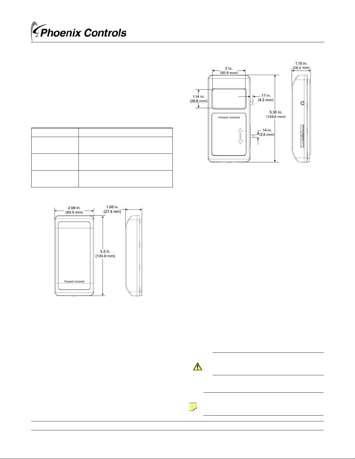
MODELS PHS300-x, PCS300-x, and PCS300-x-DOS
(where -x defines the enclosure style)
Figure 2. PCS300-x-DOS with display, override, and
slider temperature setpoint
Figure 1. PHS300-x and PCS300-x sensors only
Section 2. General Installation
Requirements
For proper installation and subsequent operation of each controller,
pay special attention to the following recommendations:
• It is recommended that the sensor(s) be kept at room temperature
for at least 24 hours before installation to allow any condensation
that may have accumulated due to low temperature during
shipping/storage to evaporate.
• Upon unpacking the product, inspect the contents of the carton
for shipping damages. Do not install damaged controllers.
• Allow for proper clearance of sensor enclosure, wiring terminals
and hardware configuration and maintenance.
• Each controller is designed to operate under the following
environmental conditions:
• Ambient temperature from 32°F to 122°F (0°C to 50°C)
• Relative humidity from 0% to 95%, non-condensing
• Ensure proper ventilation of each sensor and avoid areas where
corroding, deteriorating or explosive vapors, fumes or gases may
be present.
• Do not drop the sensor or subject it to physical shock.
If the controller is used and/or installed in a manner not specified by
Phoenix Controls, the functionality and the protection provided by the
sensor may be impaired.
CAUTION
Any type of modification to any Phoenix Controls
product will void the product's warranty.
NOTE
75 Discovery Way • Acton, MA 01720 • Tel (978) 795-1285 • Fax (978) 795-1111 • www.phoenixcontrols.com
©2014 Phoenix Controls Specifications subject to change without notice. Rev. C 650-321-017 08/16 PCS300 SERIES INSTALLATION GUIDE 1 OF 12
Take special care to keep the front and back plate aligned
when separating and joining them.
Page 2

WARNING
Take reasonable precautions to prevent electrostatic
discharges to each sensor when installing, servicing
or operating the controller. Discharge accumulated
static electricity by touching one's hand to a securely
grounded object before working with each
controller.
2.1 Mounting Instructions
NOTE
Mounting hardware is provided for both junction box
and drywall installation.
2.1.1 Junction Box
DO NOT CUT OUT THE ENTIRE JUNCTION BOX
DIMENSION. The base plate will not fully cover the opening.
1. Pull the wire through the wall and out of the junction box,
leaving about six inches free.
2. Pull the wire through the hole in the base plate.
3. Secure the base to the box using the #6-32 x 1/2" mounting
screws provided.
4. Terminate the unit according to the Termination section.
5. Attach Cover by latching it to the top of the base, rotating the
cover down and snapping it into place.
NOTE
In wall-mount applications, the wall temperature and
the temperature of the air within the wall cavity can
cause erroneous readings. The mixing of room air and
air from within the wall cavity can lead to
condensation, erroneous readings and premature
failure of the sensor. To prevent these conditions, do
the following for the mounting method used:
• Junction box - seal the conduit leading to the
electrical box
• Drywall - ensure that the foam insulating pad on
the back of the enclosure covers the hole in the
wall.
6. Secure the cover by backing out the lock-down screws using a
1/16" Allen wrench until they are flush with the bottom of the
cover.
2.1.2 Drywall Installation
1. Place the base plate against the wall where you want to mount
the sensor.
2. Using a pencil mark out the two mounting holes and the area
where the wires will come through the wall.
3. Drill two 3/16" holes in the center of each marked mounting
hole. Insert a drywall anchor into each hole.
4. Drill one 1/2" hole in the middle of the marked wiring area.
5. Pull the wire through the wall and out of the 1/2" hole, leaving
about six inches free.
6. Pull the wire through the hole in the base plate.
7. Secure the base to the drywall anchors using the #6 x 1 inch
mounting screws provided.
8. Terminate the unit according to the Termination section.
9. Attach cover by latching it to the top of the base, rotating the
cover down and snapping it into place.
10. Secure the cover by backing out the lock-down screws using a
1/16" Allen wrench until they are flush with the bottom of the
cover.
2 OF 12 PCS300 SERIES INSTALLATION GUIDE 650-321-017 08/16 ©2014 Phoenix Controls Specifications subject to change without notice. Rev. C
Page 3

2.2 General Wiring Recommendations
CAUTION
Turn off power before any kind of servicing.
Please note that there may be multiple power sources.
2.2.1 Phoenix Controls Wiring Recommendations
• Use cables recommended by Phoenix Controls (refer to Phoenix Controls Cables on page 12).
• Stranded wire of at least 22 AWG is strongly recommended for all wire connections. Larger gauge wire may be required for long runs.
• Follow good wiring practices:
• Do not run the signal cable in the same conduit or wireway as the power cables.
• If the signal cable must cross power cables, it is best to do so at a 90-degree angle.
• Maintain a consistent color code or polarity all the way through the wiring system.
• All wiring must comply with the National Electric Code (NEC) and local codes.
• Do NOT run this device's wiring in the same conduit as AC power wiring of NEC class 1, NEC class 2, NEC class 3 or with wiring used to
supply highly inductive loads such as motors, contactors and relays.
• Tests show that fluctuating and inaccurate signal levels are possible when AC power wiring is present in the same conduit as the signal lines.
If you are experiencing any of these difficulties, please contact your Phoenix Controls Representative.
• Local and national electrical codes take precedence.
Sensor connections:
• Remove the front plate from the back plate to facilitate the wiring process.
• Use a small flat screwdriver to tighten the terminal connector screws once the wires have been inserted.
• The board connectors accept wires or flat cables ranging from 22 to 14 AWG (0.64-1.63 mm diameter) per pole. However, power cables
must remain between 18 and 14 AWG (1.02-1.63 mm diameter).
Power connections:
• Power type cables (i.e., for power, 2- and 3-wire voltage and current inputs and outputs, as well as triac outputs) should be kept apart from
other types of wiring to avoid any ambient noise transmission to other wires.
• Do not connect the universal inputs, analog/digital outputs or common terminals to earth or chassis ground (unless stated otherwise).
CAUTION
Phoenix Controls does not recommend wiring the sensor with power applied as accidental arcing may damage the product and
will void the warranty.
©2014 Phoenix Controls Specifications subject to change without notice. Rev. C 650-321-017 08/16 PCS300 SERIES INSTALLATION GUIDE 3 OF 12
Page 4
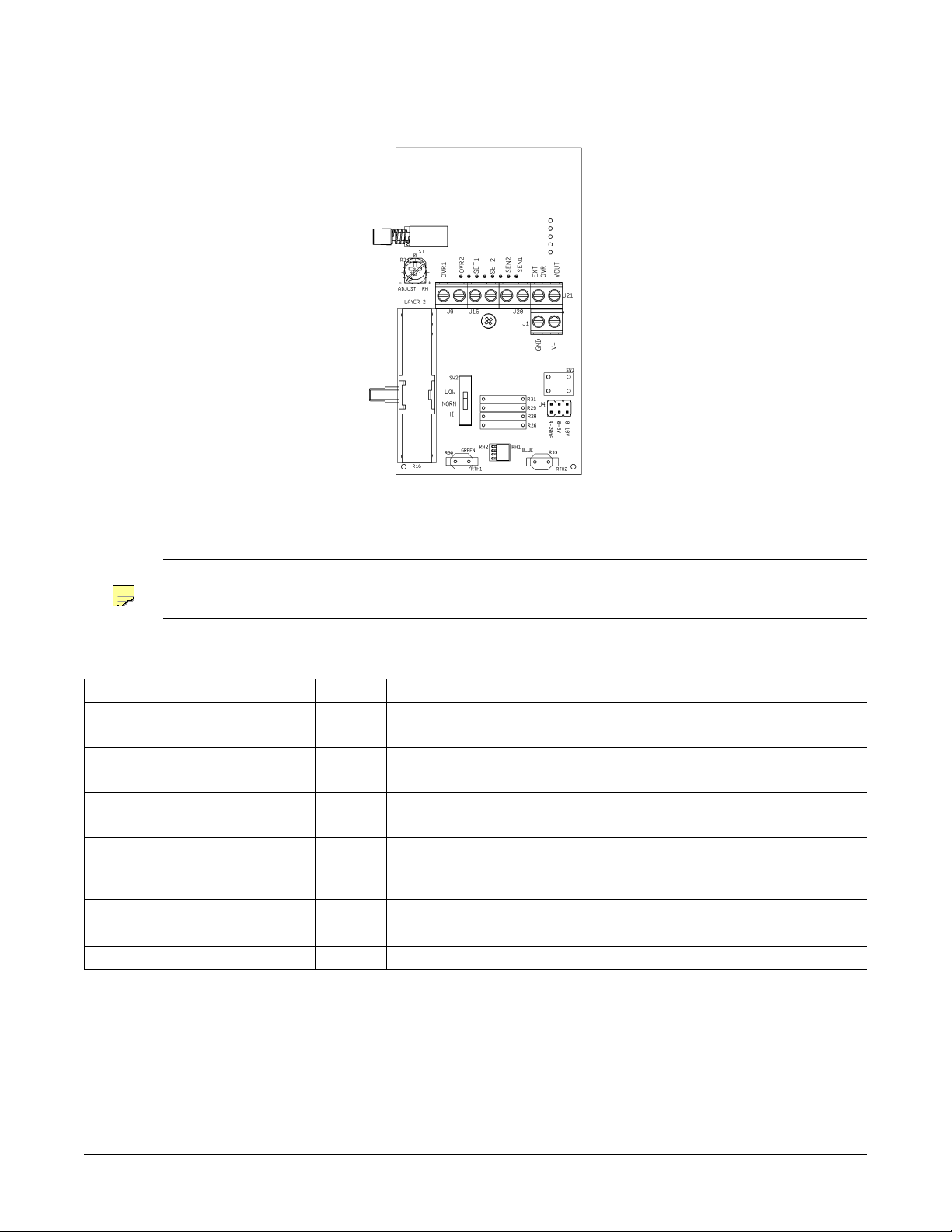
2.2.2 PHS300-x, PCS300-x, and PCS300-x-DOS Wiring
Figure 3. PHS300-x, PCS300-x, and PCS300-x-DOS connections
NOTE
PHS300-x, PCS300-x, and PCS300-x-DOS Wiring with Jumper in: 4 to 20 mA Setting
The PHS300-x and PCS300-x do not have OVR or SET terminals and the EXT-OVR and SEN terminals are non-functional.
Terminal Applicable to: Option Description
OVR1 and OVR2 PCS300-x-DOS
only
SET1 and SET2 PCS300-x-DOS
only
SEN1 and SEN2 PCS300-x and
PCS300-x-DOS
EXT-OVR PCS300-x-DOS
only
O Occupancy override status:
N.O. contact output (300 mA @ 24 Vdc)
S Temperature setpoint:
0 -20 KΩ output
Temperature sensor:
10K-2 thermistor output
D External "person" icon override:
Bypass control (from Phoenix valve) indication; "person" icon is solid (occupied) when
this pin is switched to power ground (see Bypass/External "Person" Icon Control on page 7 )
VOUT All Not used
V+ All Humidity sensor: 4-20 mA output
GND All 24 Vdc power (see Specifications on page 10 for details)
4 OF 12 PCS300 SERIES INSTALLATION GUIDE 650-321-017 08/16 ©2014 Phoenix Controls Specifications subject to change without notice. Rev. C
Page 5

PHS300-x, PCS300-x, and PCS300-x-DOS Wiring with Jumper in: 0-5 Vdc or 0-10 Vdc Settings
Terminal Applicable to: Option Description
OVR1 and OVR2 PCS300-x-DOS
only
SET1 and SET2 PCS300-x-DOS
only
SEN1 and SEN2 PCS300-x and
PCS300-x-DOS
EXT-OVR PCS300-x-DOS
only
O Occupancy override status:
N.O. contact output (300 mA @ 30 Vdc)
S Temperature setpoint:
0 -20 KΩ output
Temperature sensor:
10K-2 thermistor output
D External "person" icon override:
Bypass control (from Phoenix valve) indication; "person" icon is solid (occupied) when
this pin is switched to power ground (see Bypass/External "Person" Icon Control on page 7)
VOUT All Humidity sensor: 0-5 Vdc or 0-10 Vdc output
GND All Power ground
V+ All 24 Vdc power (see Specifications on page 10 for details)
2.2.3 Communication Jack Wiring
Figure 4. Communication jack pinout
Communication Female Jack Wiring
Communication Jack Pin Wire Color
Ground Black (Net B)
Tip White (Net A)
Ring Red (Not used)
2.2.4 Test and Balance (T&B)
Moving the Test and Balance (T&B) switch to the Normal position provides the actual room temperature. Moving the switch to HI forces a high
temperature value for the balancer or point-to-point checkout. Moving the switch to LO forces a low temperature value.
Test and Balance Switch Settings
Switch Position Description
HI Sets the sensor value HIGH for full cooling (5.11Ω, 105.8°F)
NORMAL Allows sensor to operate normally; reports actual temperature
LOW Sets sensor value low for full heating (26.7KΩ, 39.2°F)
©2014 Phoenix Controls Specifications subject to change without notice. Rev. C 650-321-017 08/16 PCS300 SERIES INSTALLATION GUIDE 5 OF 12
Page 6

2.3 Display Segments (PCS300-x-DOS only)
The normally active segments are:
• INSIDE on upper left: signifies that actual space temperature or humidity is being displayed
• SETPOINT on upper right: signifies that temperature setpoint is being displayed
• Four (4) number digits
• Three (3) integer
• One (1) decimal
•Units
• Occupancy "person" icon (solid icon = Occupied; hollow icon = Unoccupied)
Figure 5. Display segments
º
F or ºC, or relative humidity
2.3.1 Display, Setpoint, and Override Descriptions
The PCS300-x-DOS sensor comes with a display, override button, and slider setpoint adjustment.
2.3.1.1 Numerical Display
The default display shows current temperature toggled every 5 seconds with space humidity. When the setpoint slider is moved enough to change
the setpoint by 0.5 degrees, the setpoint will be displayed (as an integer) for 3 to 4 seconds. If desired, the unit can be set up to:
• to toggle between all three parameters (temperature, humidity, or temp setpoint), or
• any two parameters, or
• display one parameter only
Refer to section Humidity and Temperature Offset and Display Adjustments: PCS300-x-DOS on page 8 for details.
NOTE
2.3.1.2 Setpoint
Slide the setpoint lever up or down to the desired setpoint. When programmed to be displayed, the setpoint display changes in one degree
increments.
NOTE
The default temperature unit is Fahrenheit. To switch to Celsius, change the setting of Mode P2 as detailed in section 2.4.3
Even when the temperature setpoint is not displayed, the terminations SET1 and SET2 are active, sending a 0 to 20 KΩ, signal
out.
6 OF 12 PCS300 SERIES INSTALLATION GUIDE 650-321-017 08/16 ©2014 Phoenix Controls Specifications subject to change without notice. Rev. C
Page 7

2.3.1.3 Local Occupancy Override
When the override button is pressed, the "person" icon is solid while the output (OVR1 and OVR2) shorts. When the button is released, the icon
blanks. This functionality is seen when a ground has never been applied to the EXT OVR pin during the current power cycle. Refer to section
2.3.1.4 Bypass/External "Person" Icon control for the effect of grounding EXT OVR.
2.3.1.4 Bypass/External "Person" Icon Control
The occupancy "person" icon can be used to display bypass status from the Phoenix valve. Configure the valve's DO to output bypass occupancy
status then wire the DO between the room unit's EXT OVR and GND pins.
Once the DO closes (grounds EXT OVR), the "person" icon will become hollow (unoccupied). The icon will remain hollow until either the DO
closes again or the local occupancy override button is pushed.
NOTE
Prior to the first closing of the DO (EXT OVR grounded), the unit will behave as described in Local Occupancy Override above.
Once the EXT OVR has been grounded, the "person" icon will display continuously (either solid or hollow depending upon the
current control). The only way to blank the "person" icon from the display (after EXT OVR has been switched to ground), is to
cycle power.
2.4 Optional Technicians Adjustments
This section details optional adjustments a technician can make for:
• Changing the humidity output signal
• Adjusting humidity output (ie, offset), and
• For the PCS300-x-DOS only:
• Adjusting temperature (i.e., offset)
• Changing temperature units, and
• Changing what is shown on its display
2.4.1 Humidity Output Selection
Moving the jumper on connector J4 will change the humidity output from 4 to 20mA, 0 to 5Vdc or 0 to 10Vdc depending on jumper position.
Figure 7 below shows the jumper in the 4-20mA position.
Figure 6. Humidity output jumpers
2.4.2 Humidity Offset Adjustment: PHS300-x and PCS300-x
Potentiometer R34 (Figure 8) can be used to adjust the humidity output by ±5%. A high accuracy humidity reference is recommended.
Figure 7. R34 relative humidity (%RH) adjustment potentiometer
©2014 Phoenix Controls Specifications subject to change without notice. Rev. C 650-321-017 08/16 PCS300 SERIES INSTALLATION GUIDE 7 OF 12
Page 8

2.4.3 Humidity and Temperature Offset and Display Adjustments: PCS300-x-DOS
When the unit is powered up, pressing SW1 (Figure 9)will enter the user calibration adjustment mode. When pressed, the LCD will show the
mode as page zero, P0.
The mode page numbers auto-scroll to P5 and then the unit returns to the normal run mode. Pressing SW1 when the page number is displayed
will show the calibration value that is associated with that mode. The variable will auto-scroll to show all allowed values for the selected page.
Pressing SW1 when the variable value you need is shown will record that value and return to showing page numbers.
Figure 8. SW1 calibration button
PCS300-x-DOS Adjustment Parameters
Parameter
Temperature Offset
Humidity Offset
Mode Default Adjustment
P0 0 ±5° in 0.1° increments. A high accuracy reference is recommended.
P1 0 ±5% in 0.1% increments or R34 when R34 is selected, humidity offset is set by
turning potentiometer R34 situated just to the left of the OVR1 terminal. See
Figure 12. A high accuracy reference is recommended.
Display Units
Display RH to Temp Toggle Time
Display Resoultion
P2 F °F or °C
P3 5 3 to 11 seconds
P4 0 0 = 0.5
1 = 0.1
Display Section
P5 0 0 = Temperature, Humidity and Temperature Setpoint when active
1 = Temperature and Temperature Setpoint when active
2 = Humidity and Temperature Setpoint when active
3 = Temperature, Humidity and Temperature Setpoint
4 = Temperature and Temperature Setpoint
5 = Humidity and Temperature Setpoint
2
6 = Temperature Setpoint
7 = Temperature and Humidity
2, 3
8 = Temperature3
9 = Humidity
1
When Active means moving the setpoint slider
2
Display toggles through selections
3
Even when the temperature setpoint is not displayed the terminations SET1 and SET2 are active, sending a 0 to 20 KΩ signal out.
3
1
1
1
2
2
8 OF 12 PCS300 SERIES INSTALLATION GUIDE 650-321-017 08/16 ©2014 Phoenix Controls Specifications subject to change without notice. Rev. C
Page 9

2.5 Troubleshooting
Possible Problems Possible Solutions
General troubleshooting
Incorrect humidity
Incorrect temperature
Unit does not operate
• Determine that the input is set up correctly in the controller's and building automation software.
• Check wiring at the sensor and controller for proper connections.
• Check for corrosion at either the controller or the sensor. Clean off the corrosion, re-strip the interconnecting wire and
reapply the connection. In extreme cases, replace the controller, interconnecting wire and/or sensor.
• Label the terminals that the interconnecting wires are connected to at the sensor end and the controller end. Disconnect
the interconnecting wires from the controller and the sensor. With the interconnecting wires separated at both ends
measure the resistance from wire-to-wire with a multimeter. The meter should read greater than 10 Meg-ohms, open or
OL depending on the meter you have. Short the interconnecting wires together at one end. Go to the other end and
measure the resistance from wire-to-wire with a multimeter. The meter should read less than 10 ohms (22 gauge or
larger, 250 feet or less). If either test fails, replace the wire.
• Check power supply/controller voltage supply
• Disconnect sensor and check power wires for proper voltage (see specifications page)
• Check all adjustments
• If available, check the sensor against a calibrated instrument such as a hygrometer
• Determine if the sensor is exposed to an external environment different from the room (conduit draft)
Determine that the temperature sensor's wires are connected to the correct controller input terminals and are not loose.
• Check the wires at the sensor and controller for proper connections.
• Determine if the sensor is exposed to an external environment different from the room (conduit draft)
• Measure the physical temperature at the temperature sensor's location using an accurate temperature standard.
Check the Temperature Sensor's Resistance
Disconnect the temperature sensor's wire (Terminals SEN1 & SEN2) and measure the temperature sensor's
resistance across the sensor output pins with an ohmmeter. Put the ohmmeters black lead on Terminal SEN2
and the red lead on Terminal SEN1. Compare the temperature sensor's resistance to the thermistor output
table on the Temperature and Humidity Sensors Product Data Sheet (MKT-0165). If the measured resistance is
different from the temperature table by more than 5%, call Phoenix Controls Technical Support. Don't forget
to reconnect the wires.
Check power for proper polarity.
• Disconnect the power wires at the controller. Measure controller output for proper power (see specifications), if the
voltage is outside the limits trouble shoot controller. Reconnect power wires to controller when finished. If the measured
voltage is above the specification limit, you may have damaged the sensor, call Phoenix Controls Technical Support.
• Disconnect the power wires at the sensor. Measure the wires for the same voltage as at sensor. If the voltage is different
from that measured at the controller troubleshoot wire. Reconnect power wires to sensor when finished.
• Measure the power at the sensor with the power connected for proper power (see specifications), if the voltage is outside
the specification limits call Phoenix Controls Technical Support
©2014 Phoenix Controls Specifications subject to change without notice. Rev. C 650-321-017 08/16 PCS300 SERIES INSTALLATION GUIDE 9 OF 12
Page 10

2.6 Specifications
PHS300-x PCS300-x PCS300-X-DOS
POWER
POWER
CONSUMPTION
With humidity output of:
0 to 5 Vdc or to 10 Vdc
SENSING ELEMENTS Thermistor
Temperature Range
Temperature Accuracy
Temperature Stability
Heat Dissipation
Humidity
Humidity Range 0-100% RH
Humidity Accuracy
Response Time 20 seconds for a 63% step
FEATURES Display
Te m pe r a t u r e
Humidity
Tem p Se t p oi n t
Temp Setpoint Display Range
Override
Override Display
Tes t a nd B a l an c e
Network Connection 1.8" (3.5 mm) phone jack in base
OUTPUTS Temperature
Tem p er a t ur e S et p oi n t
Occupancy
Humidity as Voltage 0-5 or 0-10 Vdc; Impedance > 10 KΩ
Humidity as Current 4-20 mA; Impedance <500 ohm @ 24 Vdc
ENCLOSURE Material Type ABS Plastic
Material Rating UL 94, V-0
MOUNTING Drywall Anchor and screws provided
Junction Box Standard 2" x 4" J-box; screws provided (not box)
ENVIRONMENTAL Temperature
Humidity 0 to 95%, non-condensing
10 to 35 Vdc (24 Vdc recommended)
Note: Use of PVC350-HW is required for LON applications
———
4-20 mA
20 mA (0.5 VA)
4 mA (0.1 VA)
— 10 KΩ @ 25
—
— ±0.36
— <0.036
— 4.9 mW /
± 2.0% RH (from 10 to 90% RH at 77
——
——
Forma t
——
——
——
Feature 2
——
Feature 3
——
Feature 7
——
Feature 8
——
Feature 9
——
——
——
— 3-position slide switch (High / Norm / Low)
—
——
——
º
to 122ºF (0º to 50ºC)
32
º
to 122ºF (0º to 50ºC)
32
º
F, ( ±0 .2ºC)
º
F / Year (<0.02º C / Year)
º
º
F (25ºC)
Resistance, NTC
º
C, Type 2
F (2.7 mW / ºC)
LDC; 3.5 digits at 0.6" H
º
to 122º F (0º to 50º C)
32
º
in 0.5
increments
0 to 100% RH in 0.5% increments
Default: Temperature and Humidity
toggled every 5 seconds; Temp Setpoint
only when slider moved
Slide pot
Cool / Warm (Down / Up)
Configurable at valve UI:
Absolute 32-122
Relative -18 to +18
Shown in 1
º
± 2
F (± 2º C)
º
± 3
F (± 3º C)
55 to 85
60 to 80
65 to 80
º
F (0-50º C)
º
F (-7 to +7º C)
º
increments:
º
F (13 to 30º C)
º
F (15 to 27º C)
º
F (18 to 27º C)
N.O. Pushbutton (closed during push)
Occupancy "person" icon
Solid=Occupied
0-20 KΩ
N.O. contact
10 OF 12 PCS300 SERIES INSTALLATION GUIDE 650-321-017 08/16 ©2014 Phoenix Controls Specifications subject to change without notice. Rev. C
Page 11

2.7 Maintenance
CAUTION
Each controller requires minimal maintenance, but it is important to take note of the following:
• If it is necessary to clean the outside of the front plate and/or the inside of the back plate, use a dry cloth.
• Verify the tension of all wires and cables whenever the controller is serviced.
Turn off power before any kind of servicing.
Note that there may be multiple power sources.
2.8 Disposal
The Waste Electrical and Electronic Equipment (WEEE) Directive sets out regulations for the recycling and disposal of products. The WEEE2002/
96/EG Directive applies to standalone products, i.e., products that can function entirely on their own and are not a part of another system or piece
of equipment.
For this reason Phoenix Controls products are exempt from the WEEE Directive. Nevertheless, Phoenix Controls products are marked with the
WEEE symbol, indicating that disposal of the devices shall not be done together with municipal waste.
Figure 9. WEEE Directive symbol
Products must be disposed of at the end of their useful life according to local regulations and the WEEE Directive.
2.9 FCC Statement
CAUTION
FCC: This device complies with part 15 of the FCC Rules. Operation is subject to the following two conditions:
1. This device may not cause harmful interference.
2. This device must accept any interference received, including interference that may cause undesired operation.
©2014 Phoenix Controls Specifications subject to change without notice. Rev. C 650-321-017 08/16 PCS300 SERIES INSTALLATION GUIDE 11 OF 12
Page 12

2.10 Phoenix Controls Cables
Cable
Ty p e
2C Round No 24 Vac power 18 Belden 9409 1: Red
2C Round Yes 24 Vac power 18 Belden 82740 Windy City
TP NO FTT-10 (4,500 FT)
TP Yes FTT-10 (4,500 FT)
3C Round No Signal 22 Belden 8443 1: Red
3C or 4C
Round
4C Round No Signal 22 Belden 8444 Manhattan M13304 1: White
5C Round No Signal 22 Belden 8445 Manhattan M13305 1: White
8C No Signal 22 Belden 9421 Manhattan M13308 1: White
8C Yes Signal 22 Comtran 4956 1: White
3C
MS/TP
3C
MS/TP
Plenum
Rated
Yes Signal 22 Belden 88444 Windy City 004380 1: Red
No Shielded 22 Belden 3106A
Yes Shielded 22 Connect-Air W223C-
Function
24 Vac power 14 Belden 9411
24 Vac power 14 Windy City NP007960
TP1250 (425 FT)
FTT-10 (8,000 FT) 16 Windy City 109600
TP1250 (425 FT)
FTT-10 (8,000 FT) 16 Windy City 109500
Wire
Gauge
22 Windy City 107500
22 Windy City 105500
Primary
Vendor/Part #
www,smartwire.com
www,smartwire.com
S=SPOOL B=BOX
www,smartwire.com
(120 ohm)
2060YPC
Alternate Vendor/
Part #
NP002360
2: Black
1: Red
2: Black
1: White with Blue Stripe
2: Blue with White Stripe
1: White with Blue Stripe
2: Blue with White Stripe
2: Black
3: Green
2: Black
3: Green
4: White (not used as 3C)
2: Green
3: Black
4: Red
2: Brown
3: Black
4: Red
5: Green
2: Orange
3: Black
4: Red
5: Green
6: Yellow
7: Blue
8: Brown
2: Orange
3: Black
4: Red
5: Green
6: Yellow
7: Blue
8: Brown
1: White with Orange stripe
2: Orange with White stripe
3: Blue with White stripe
1: Black
2: White
3: Red
Color Code Notes
Must be stranded
Must be stranded
Must be stranded
Must be stranded
Must be stranded
Must be stranded
No substitutes
No substitutes
Shielded with
drain
Foil shield with
drain wire
Phoenix and Phoenix Controls are trademarks of Honeywell International, Inc.
The material in this document is for information purposes only and is subject to change without notice. Phoenix Controls assumes no responsibility for any errors
or for consequential damages that may result from the use or misrepresentation of any of the material in this publication.
Phoenix Controls is a business of Honeywell International, Inc.
For additional information and a listing of our global offices, please visit our Web site at www.phoenixcontrols.com or call (800) 340-0007.
12 OF 12 PCS300 SERIES INSTALLATION GUIDE 650-321-017 08/16 ©2014 Phoenix Controls Specifications subject to change without notice. Rev. C
 Loading...