

Phoenix MSD 50HPS-120, MSD 100HPS-120, MSD 70HPS-120, MSD 150HPS-120 Installation Instructions And Parts List
Page 1
7
PHOENIX
INSTALLATION INSTRUCTIONS AND REPAIR PARTS LIST FOR
HIGH PRESSURE SODIUM INTEGRAL BALLAST FLOODLIGHTS
120 VOLTS, 50-150 WATTS
Models MSD 50HPS-120, MSD 70HPS-120, MSD 100HPS-120, MSD 150HPS-120
LAMPING
Before lamping or re-lamping, make sure t hat power is turned
off to the fixture.
To gain access to the lamp compartment, loosen 10 captive
screws (Item 12) in the removable cover (Item 23). (Cover
nearest 1/2 in. NPSI ho le). DO NOT REMOVE BARRIER
(Item 27). DO NOT REMOVE THE FIXED COVER (Item 22)
WHICH HAS THE LAMP SOCKET ATTACHED TO IT.
Screw lamp into socket. Reinstall removable cover (Item 23)
and tighten 10 screws (Item 12) to 15 in-lbs. The fixt ure can
be mounted and electric power connected.
CAUTION
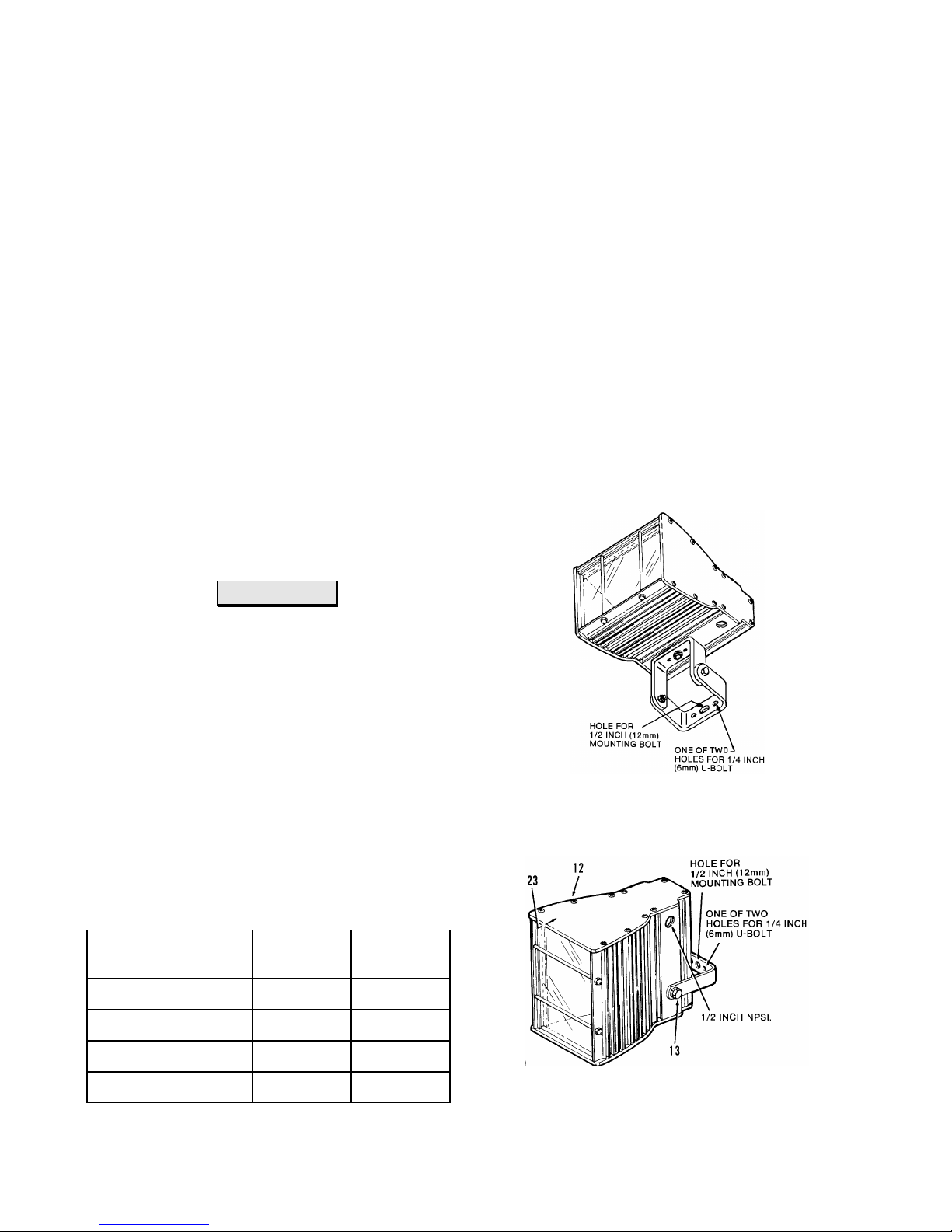
MOUNTING
Vertical or horizontal mounting kits must be ordered with
fixture. Insert one 1/2 inch (12mm) stainless steel bolt
through the mounting hole provided in the mounting bracket
and secure with appropriate lock washer and nut on t he oth er
side of the mounting fixture. When mounting on a maximum
1-3/4" OD pole or mast, a 1/4 inch (6mm) stainless steel Ubolt may be inserted in the holes provided in the bracket and
1. Operate fixture ONLY with PRO PER lamp. The internal
ballast in each fixture is designed to accommodate a specific
wattage lamp. See LAMP RECOMMENDATIONS.
2. If the lamp fails, replace lamp or disconnect primary
power to fixture within two weeks at the most. Otherwise,
permanent damage to electrical components may resu lt fro m
high voltage pulses unique to High Pressure Sodium circu its.
3. Use protective gloves and safety eyeglasses when
replacing lamps.
If outer glass bulb is broken, turn off lamp and replace it
promptly to avoid exposure to ultraviolet energy. Even with
lamp outer glass enclosure broken, the arc tube may
continue to fire.
Fixture Model No.
MSD-120-50HPS
MSD-120-70HPS
MSD-120-100HPS
LAMP RECOMMENDATIONS
Wattage
50
70
100
Phoenix
Part No.
4211300
4212600
4212700
the fixture secured with appropriate lock washers and nuts.
NOTE: Mounting hardware isn't provided with fixture.
MSD-120-150HPS
150
N5488100F-1
4212800
HORIZONTAL MOUNTING-USE KIT NO. 1090170
VERTICAL MOUNTING-USE KIT NO. 1090160
Page 2

REPAIR PARTS LIST
1 2
2 1
3 1
4 3
5 1
6 1
8 1
9 2
4
2
1
3
3
3
3
1
1
2
1
1
1
1
1
1
ITEM QTY. DESCRIPTION
End Cover Gasket
Socket Insulator
Black EPDM Grommet
Spacer
Reflector
Bracket For Capacitor & Ignitor
10
11
12
15
16
17
7
20 S.S. Thread Forming Type B, Captive Screw, #8 x 1
Mounting Bracket Vertical Mount ing
1
Mounting Bracket Horizontal M ounting
Cable Assembly
Threaded Rod
S.S. Hex Head Close-Acorn Nut, 6-32
S.S. Slotted Pan Head Machine Scr ew 6-32 x .25
S.S. Green Nut, hex 10 -32
Threaded Rod
S.S. Hex Nut, 6-32
PART NUMBER
5005600
4052600
5005500
7523400
2693901
2310600
1090160
1090170
7508500
2694601
6220200
6007700
6022300
6203900
2694602
6201700
18
19
20
21
22
23
24
25
26
27
28
S.S. Split Lockwasher, #6
Cable Tie
Capacitor-Includes (3) Cable Ties, I tem 19
50 Watt - (MSD 120 - 50 HPS)
70 Watt - (MSD 120 - 70 HPS)
100 Watt - (MSD 120 - 100 HPS)
1
150 Watt - (MSD 120 - 150 HPS)
Lamp Socket
Fixed Cover Kit (Lamp Socket Side) Including: Reflector, Gasket, and Label
1
(Preassembled), (10) #8 x 1" Lg. Screws
Removable Cover Kit Including: Reflector and G as k et (Preassembled), (10) #8 x 1"
1
Lg. Screws
Glass Kit With (2) Gaskets
Reflector - Includes (1) Gasket, Item 1
Ballast & Ignitor - Includes (3) Cable Ties, Item 19
50 Watt - (MSD 120 - 50 HPS)
70 Watt - (MSD 120 - 70 HPS)
100 Watt - (MSD 120 - 100 HPS)
1
150 Watt - (MSD 120 - 150 HPS)
Barrier
Screw, Thread Forming T ype B #8 x 3/8
6312900
4052200
1076100
1076200
1076300
1076400
4503700
1074900
1075000
1075100
2693901
1076800
1076900
1077000
1077100
2701700
6021000
29
30
31
32
Nut U-Type #8
Washer, Flat
Washer, Terminal
Washer, Lock, External Toothed #10
N5488100F-2
6241500
6302700
6321100
6310400
Page 3

REPAIR PARTS ILLUSTRATION
N5488100F-3
Page 4

MS-120V 50-150W HPS Series Installation Instructions
CAUTION
All wiring should be done by licensed electricians in
accordance with state and local codes plus National
Electric Code (NEC) standards. Improper
installation may result in serious injury.
WIRING
Before making any electrical connections, make sure that
power is turned off to the incoming wires.
Loosen ten screws (Item 21) in the removable cover (Item
23). (Cover nearest the 1/2 inch NPSI hole). Remove
barrier (Item 27) for access to wiring compartment.
The wiring compartment now revealed contains a common
wire and a 120 volt lead wire. They are labeled as such.
Connect the appropriate incoming wires to these wires.
Electrical fittings and conductors appropriate for the
application and in compliance with accepted codes must be
used. The green screw inside the compartment is g round ed
to the fixture and must be connected to a positive ground.
DON'T CONNECT GREEN (GROUND) WIRE TO POWER
SOURCE.
When wiring is completed, reinstall the barrier, (Item 2 7 ).
Reinstall the removable cover (Item 23).
PHOENIX PRODUCTS COMPANY, INC.
8711 West Port Avenue ! Milwaukee, WI 53224 U.S.A.
Phone: 414.973.3300 ! FAX: 414.973.3210
www.phoenixproducts.com
CAUTION
Before cleaning, make sure the fixture is turned off.
CLEANING
When re-lamping, it is recommended that the glass on the
fixture be cleaned to maintain fixture efficiency. This glass
may be cleaned with any non-abrasive conventional glass
cleaner.
The reflector should also be cleaned at this time. Use a soft
cloth with warm, soapy water.
AIMING - HORIZONTAL MOUNTING
Vertical aiming is achieved by loosening the two bolts which
fasten the two mounting harps together. Re-tighten the
bolts when the fixture is in the desired position.
AIMING- VERTICAL MOUNTING
Vertical aiming is accomplished by loosening the two bolts
which fasten the mounting bracket to the fixture. Vertical
travel is about 30 up and 100 dow n. Re-tighten the bolts
when the fixture is in the desired position.
The angle of the fixture can also be adjusted by loosening
the mounting bolts in the mounting bracket, rotating the
fixture to the desired angle and then re-tightening the bolts.
N5488100F-4
 Loading...