

Page 1

PROFESSIONAL SOUND EQUIPMENT
MANUAL
MPA 6-150
http://www.phoenix-pa.com; e-mail:info@phoenix-pa.com
Page 2

MPA - Professional Power Amplifier
WARRANTY
Phoenix guarantees, that every new product purchased at an authorized distributor is free of
assembly and material and material defects.
During the guarantee, the purchaser is entitled to repairs free of charge in cases ivolving
assembly defects.
Defects reported during the time of the guarantee will be repaired by an authorized dealer
free of charge within 21 days from the date that the equipment is delivered for repair - the time
of repair may be extented if the job requires parts to be acquired from another country.
The guarantee is extended by the time it takes to complete reparations of the product.
Under the guarantee, those repairs for which instructions are given in the manual will not
be cover, and are the sole responsiblity of the owner’s time and cost. For example, the installation
of equipment, the testing, maintenance (especially the cleaning of the filter), and interchanging
the fuses. All of the afore mentioned repairs can be made by the dealer at the customer’s own cost.
Guarantee does not cover:
- Mechanical, chemical, and thermal damages inflicted on the equipment.
- Damages and defects caused by wrongful installation, usage, storage, and maintenance.
- Damages caused by repairs and changes to the equipment made by the customer or other
unauthorized persons.
- Damages attributed to acts of god.
The owner provides damaged equipment for repairs or sale at his or her time and cost, preferably
in the original package. If the original package is missing, the risk of product damage is higher
and the owner assumes all financial losses.
Without the registration card, equipment will not be repaired.
Page 3

MPA - Professional Power Amplifier
SAFETY TIPS
EQUIPMENT SETUP
Avoid setting up the equipment areas:
- subject to direct sunlight
- exposed to high temperatures
- exposed to moisture
- subject to high vibrations
- on an uneven surface
Non compliance can lead to damaging the outside frame and/ or other parts which could shorten the allotted time of operation.
VENTILATION
Install the equipment in the area with proper ventilation - with a distance of at
least 10cm from the rear of the device to the wall. Remember that objects such
as curtains should not cover the ventilation openings.
PLACING OBJECTS ON TOP OF THE AMPLIFIER
Do not place heavy object on top of the amplifier or on the electrical cord.
Such actions could cause the top plate to be permanently deformed or the electrical
cord to be severed.
VOLTAGE
The equipment cannot be plugged into a DC socket. Make sure the parameters
of the socket are known.
ELECTRICAL CORD
When inserting the electrical cord into the socket, hold the plug firmly and make
sure it is propely placed into the socket. Never attempt to touch the socket with
moist hands.
Avoid cutting, scratching, over bending, stretching, and folding the electrical cord.
Such actions could cause a fire or electrical shock.
When unplugging the cord do not pull the wire because an electrical shock could
result.
FOREIGN OBJECTS
- Do not allow objects such as needles, coins, screws, etc to accidentally fall into
the equipment through the ventilation openings. The result could be serious
damage to the amplifier and electrical shock.
- At no time should water or any other liquid to be spilled on or into the equipment
due to the high risk of fire or shock.
- Avoid using any aerosol sprays around the equipment.
SERVICE
Never try to take apart, fix or repair the equipment. If problems arise at time of operation
(interrupted sound, signals do not light up, traces of smoke arise, etc.) Immediately turn off the
amplifier and contact an authorized dealer. If the equipment will not be used for an extented period
of time , unplugged the amplifier from the outlet.
MAINTENANCE
Clean the frame, the main frame, and the regulator witch a soft moist towel, lightly covered
with a gentle detergent. Do not use any abrasive materials or detergents. Do not use any solvent
such as alcohol or gasoline.
Page 4
MPA - Professional Power Amplifier
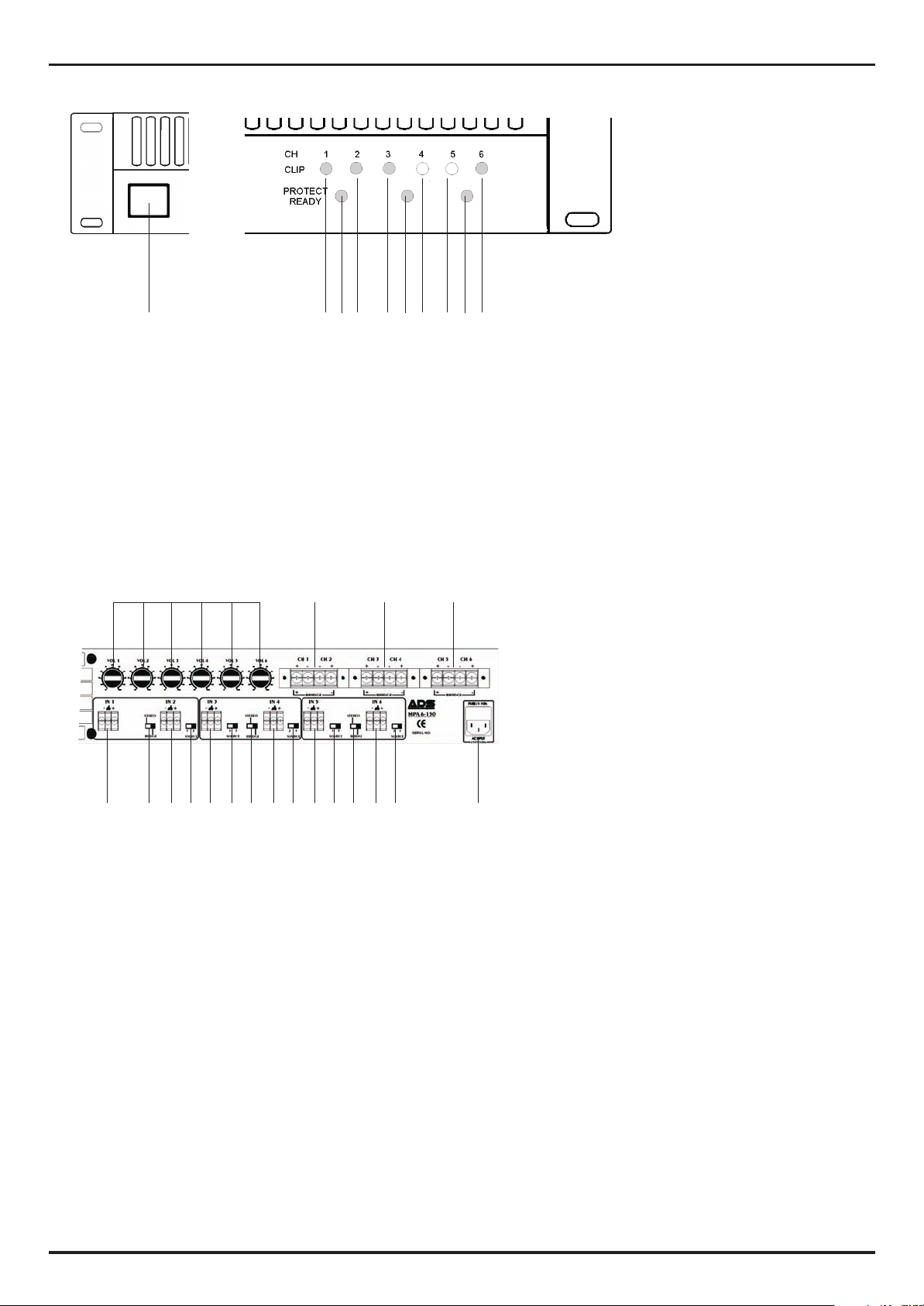
FRONT PANEL
2 3 4 5 6 7 8 9 101
1. POWER switch
3,6,9. Operating signal READY/PROTECT
- signal lights up green - amplifier ready to operate
- signal lights up red - signifies that, safety switch is eliminating
Banging at time of startup
Apearance of DC
Overheating of theheatsink or transformer
2,4,5,7,8,10.. Indication directing amplifier CLIP/ SIGNAL ( CH1 - CH 6)
- signal lights up green - showing present signal of output
- signal lights up red - informs the user that the entering signal is too large
REAR PANEL
1 2 3 4
5 6 7 8 9 10 11 12 13 14 15 16 17 18 19
1.
VOL1 - VOL6 parameters regulate the amplitude of outgoing signals
2.
OUTPUT ( CH1, CH2, BRIDGE )
3. OUTPUT ( CH3, CH4, BRIDGE )
4. OUTPUT ( CH5, CH6, BRIDGE )
5. INPUT connector ( IN1 )
6. Operation mode switch ( STEREO, BRIDGE )
7. INPUT connector ( IN2 )
8. Source switch for CH 2
9. INPUT connector ( IN3 )
10. Source switch for CH 3
11. STEREO, BRIDGE switch
12. INPUT connector ( IN4 )
13. Source switch for CH 4
14. INPUT connector ( IN5 )
15. Source switch for CH 5
16. STEREO, BRIDGE switch
17. INPUT connector IN6
18. Source switch for CH 6
19. AC Power Line IN
Page 5
MPA - Professional Power Amplifier
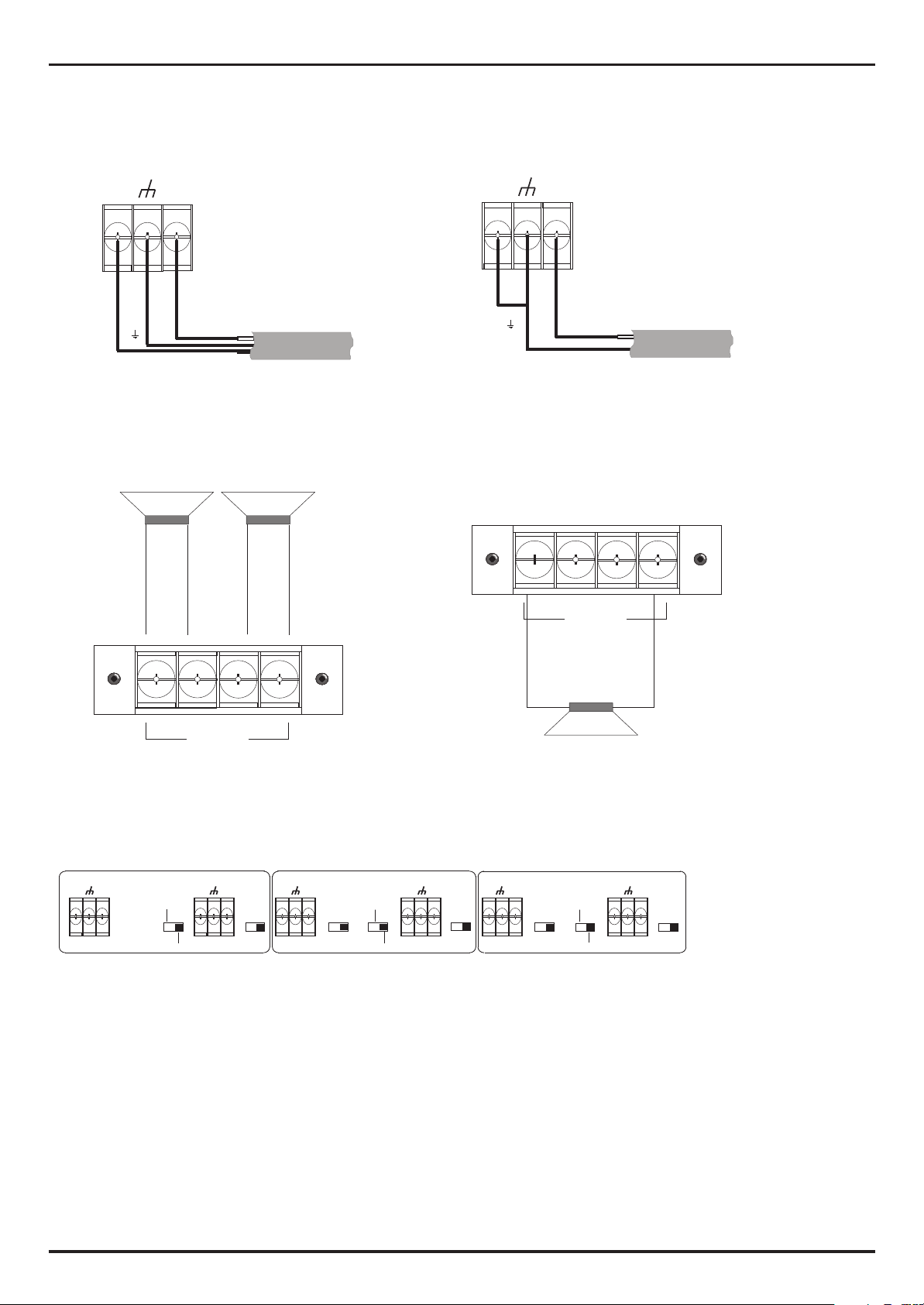
INPUT CONNECTOR
BALANCED
-
-
GND
+
+
OUTPUT CONNECTOR
STEREO
UNBALANCED
-
GND
+
+
BRIDGE
CH 1 CH 2
+ - - +
CH 1 CH 2
+ - - +
+ -
BRIDGE
SOURCE SWITCHES
IN 1 IN 2
-
+
STEREO
BRIDGE
-
+
+ -
IN 3 IN 4 IN 5 IN 6
1 2
SOURCE
-
+
1 3 2 4 1 5 2 6
SOURCE
STEREO
BRIDGE
-
+
SOURCE
-
+
SOURCE
BRIDGE
STEREO
BRIDGE
-
+
SOURCE
Page 6
MPA - Professional Power Amplifier
Multichannel power amplifier MPA 6-150
Six independent amplifier channels and three bridging switches provide max. Configuration flexibility.
Separate gain controls on the back panel allow convenient level balancing of all channels .
It features high quality 100W RMS amplifiers per zone.
- six independent channels
- bridge operation available
- phoenix input connector
- output screw terminals
- separate gain controlers
- source switch parallel operation mode
- silent switching on and of loading
- variable speed fan
- mosfet output transistors
- toroidal transformer inside
- protection system ( output current redeuction at low impedance - short circuit , over temp protection)
- clip indicator for each channel
- protect/ready indicator for each pair channels
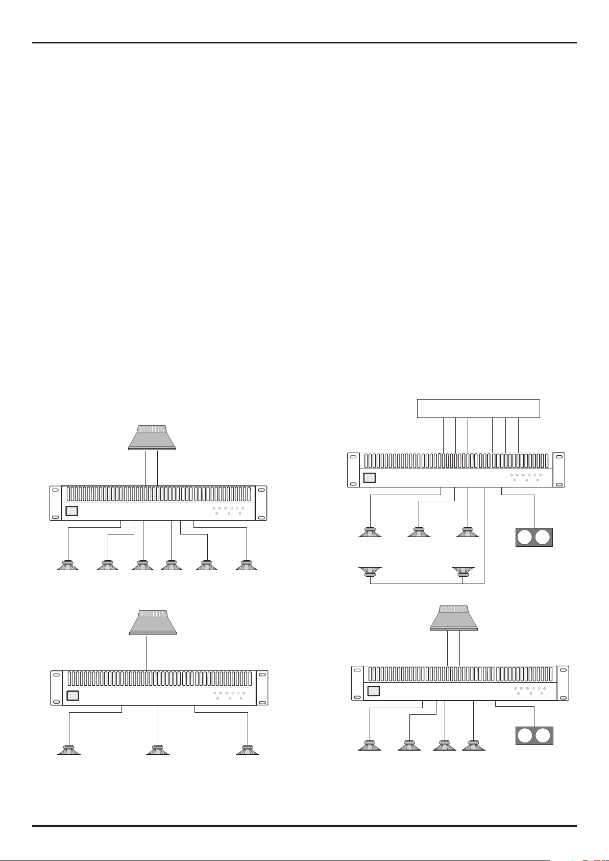
Sample aplicatins
MPA 6-150
MULTICHANNEL POWER AMPLIFIER
MPA 6-150
MULTICHANNEL POWER AMPLIFIER
CH 1 2 3 4 5 6
CLIP
PROTECT
READY
CH 1 2 3 4 5 6
CLIP
PROTECT
READY
PROCESOR SURROUND
FL C FR RL RR
MPA 6-150
MULTICHANNEL POWER AMPLIFIER
FRONT L
REAR L REAR R
CENTER FRONT R
MPA 6-150
MULTICHANNEL POWER AMPLIFIER
SUB
CH 1 2 3 4 5 6
CH 1 2 3 4 5 6
CLIP
PROTECT
READY
SUBWOOFER
CH 1 2 3 4 5 6
CLIP
PROTECT
READY
SUBWOOFER
Page 7
MPA - Professional Power Amplifier
SPECIFICATIONS
Output Power ( 1kHz ) Dual
Channels/
Loads 1/1 4/4 6/6
Ohm 4 8 4 8 4 8
Output 150 85 120 75 100 70
Output Power ( 1kHz ) Mono
Channels/
Loads 2/1 4/2 6/3
Ohm 4 8 4 8 4 8
Output N/A 300 N/A 240 N/A 200
- Frequency response 20Hz - 20kHz @ 1W +/- 1dB
- Distortion THD 0,1 % @ 1kHz
- Input sensitivity 1V
- Input impedance 10kohm unbalanced,, 20kohm balanced
- Signal to Noise 95dB
- Damping factor > 300
- Dimensions ( W x H x D )mm 483 x 88 x 420
- Weght 12,3 kg
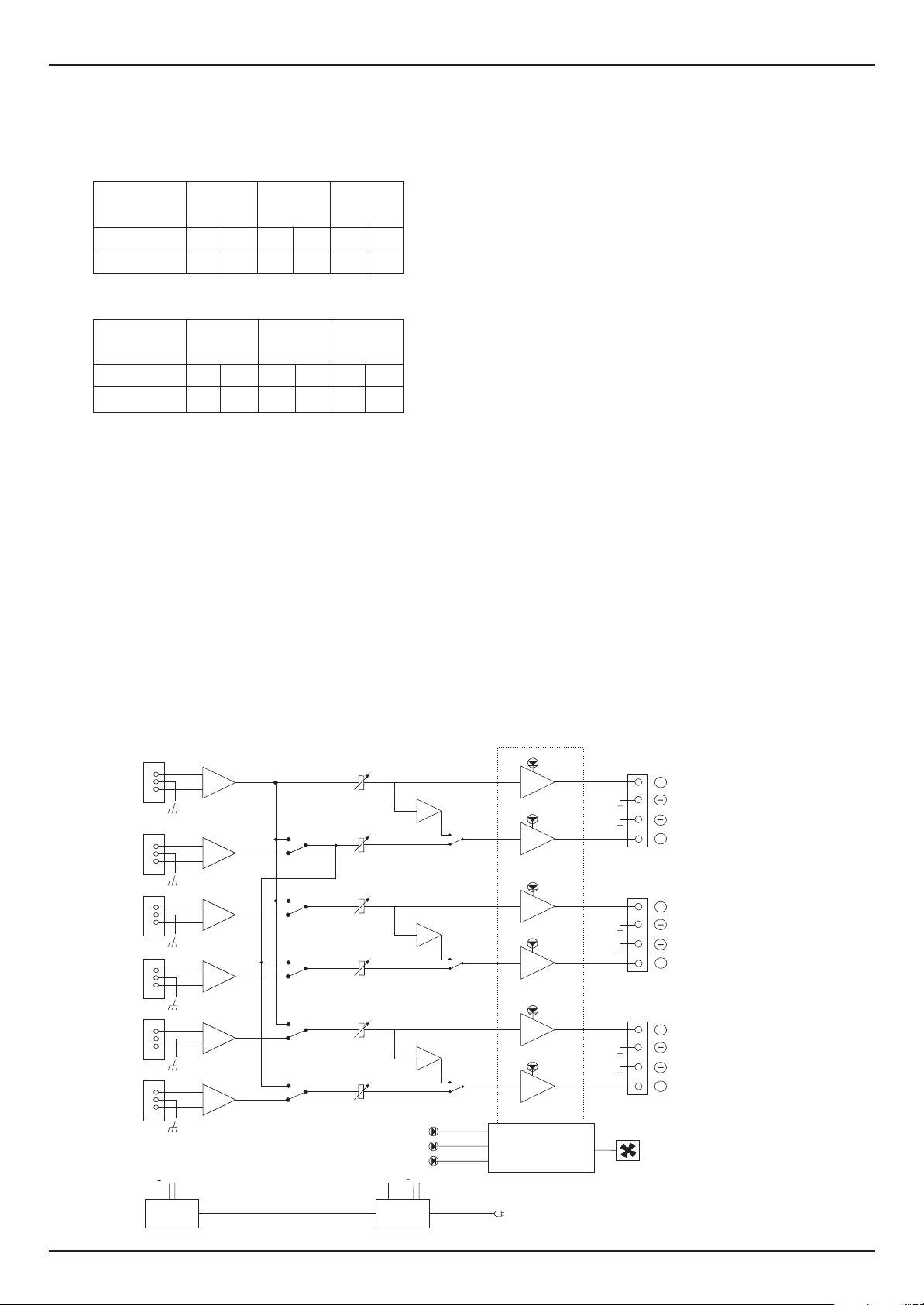
Block Diagram
INPUT SOURCE
IN
-
IN 1IN 1
+
-
IN 2
+
-
IN 3
+
-
IN 4
+
-
IN 5
+
-
IN 6
+
+
Vcc
INPUT
STAGE
SUPPLY
V
OLUM
OLUM
E
EV
S
S
TA
TA
SWITCHES
G
G
E
EIN
P
P
UT
UT
VOLUME
CONTROL
VOL 1
1
1
2
3
4
5
6
2
1
3
2
4
1
5
2
6
VOL 2
VOL 3
VOL 4
VOL 5
VOL 6
FAN
I
I
N
N
INP
I
I
N
N
PROTECT
READY
+
POWER
SUPPLY
M
PUT
PUT
STA
STA
-1
U
U
T
T
S
S
-1
PUT STA
PUT STA
-1
Vss
ODEMODE
T
T
G
G
E
E
BRIDGE
STEREO
A
A
G
G
E
EINP
BRIDGE
STEREO
G
G
E
E
BRIDGE
STEREO
POWER
AMPLIFIER
CLIP
CLIP
CLIP
CLIP
CLIP
CLIP
PROTECT
MAINS
SPEAKERSMODE
FAN
OUT
CH 1
CH 2
CH 3
CH 4
CH 5
CH 4
P
P
UT
UT
S
S
T
T
A
A
G
G
( + ) BRIDGE
+
( ) BRIDGE
+
( + ) BRIDGE
+
( ) BRIDGE
+
( + ) BRIDGE
+
( ) BRIDGE
+
E
EOUT
-
-
--
--
 Loading...