

Page 1
Meridian Series
Installation Instructions
CAUTION
!
• All wiring should be done by a licensed electrician in accordance with state codes, local codes, and National Electrical Code (NEC) or International Electric
Commission (IEC) standards.
• Improper installation may result in serious injury and void warranty.
• Contains parts and assemblies susceptible to damage by electrostatic discharge (ESD).
• Surge protective devices should be utilized for fixtures installed in environments subject to power surges outside the specified operating parameters.
Tools and Materials
(1) #3 Phillips head screw driver
(1) ¾ inch wrench
(1) ⁄ inch wrench
(1) ½ inch wrench
(1) channel lock pliers
Mounting
There are several options available for mounting the Meridian Series. Installation instructions for the two primary options are provided below. Follow the one that
corresponds to your application.
250 Model Weight 500 Model Weight
14.0 kg (31.0 lb) 18.0 kg (40.0 lb)
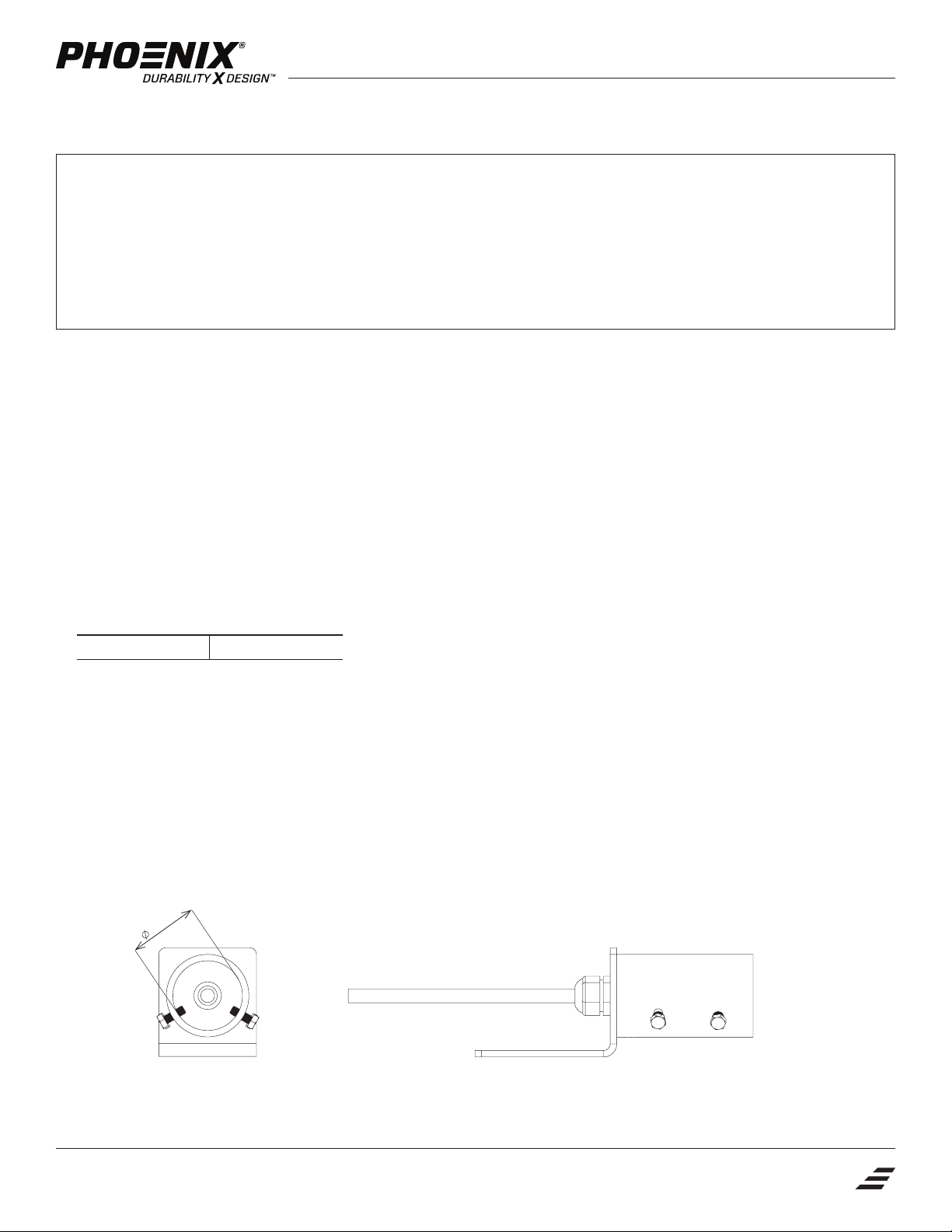
Pipe Mount
1. Verify the voltage listed on the product label is the same as the voltage to be supplied to the fixture.
2. Verify outer pipe diameter matches pipe mount adapter (Figure 1).
3. Attach pipe mount adapter to the trunnion bracket using two ⅜ inch cap screws, two split lock washers and two flat washers. Torque screws to 24-27 N-m.
4. Install cord grip to pipe mount using the cord grip nut provided (Figure 2).
5. Thread power supply cord through cord grip on pipe mount adapter. Pull cord through so 300-380 mm remain on the fixture side of the adapter (Figure 2).
Tighten cord grip, hand tight plus ¼ turn.
6. Lift fixture and slide pipe mount adapter onto pipe.
7. Install four ⁄ cap screws into adapter. Rotate fixture to desired orientation and tighten screws to 13-16 N-m.
6.43 mm
Figure 2Figure 1
Phone: +1 414.973.3300 Toll Free: 800.438.1214 Fax: +1 414.973.3210 www.phoenixlighting.com
Phoenix Lighting 8711 West Port Avenue Milwaukee, WI 53224 USA
1
Page 2
Meridian Series
Installation Instructions
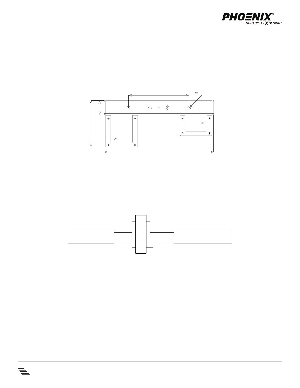
Trunnion Mount
1. Verify the voltage listed on the product label is the same as the voltage to be supplied to the fixture.
2. Attach fixture to a structure suitable to the weight and size of the fixture using two (2) 12 mm stainless steel screws (not provided). Tighten bolts
to 54-60 N-m. If mounting to a vertical surface, mount with junction boxes below the mounting bracket if space allows (see Figure 3).
Figure 3
250 mm (9.84 in) 13.9 mm
60 mm (2.36 in)
194 mm (7.62 in)
control box
451 mm (17.74 in)
Wiring
1. Using a Phillips head screw driver, remove cover from the supply power junction box.
2. Pull the main power cord through the open cord grip into the junction box.
3. Make wiring connections per the diagram below (Figure 4). Gently pull on each wire to ensure terminals are tight.
4. With jacket of power cord visible inside junction box, tighten cord grip, hand tight plus ¼ turn.
5. Reattach junction box cover. Tighten screws to 0.8 N-m.
Figure 4
fixture cord
black
ground
white
L
G
N
line
ground
neutral
incoming power
supply power junction box
2
Phoenix Lighting 8711 West Port Avenue Milwaukee, WI 53224 USA
Phone: +1 414.973.3300 Toll Free: 800.438.1214 Fax: +1 414.973.3210 www.phoenixlighting.com
Page 3

Meridian Series
Installation Instructions
Aiming
If available, refer to the lighting design layout for specific aiming details.
The fixture offers predefined, adjustable aiming of 5, 10, 15, and 20 degrees in either direction from 0 (Figure 5). To adjust mounting angle, loosen (do not remove)
bolts (2) holding fixture to mounting bracket. Remove the two quick release pins. Rotate to desired angle and replace pins. Retighten bolts to 24-27 N-m.
If fixture is provided with a pole mount adapter, the fixture can also be rotated horizontally as needed. Loosen the two bolts holding the fixture to the adapter,
rotate to the desired orientation and retighten screws (Figure 6).
Figure 5 Figure 6
-5
-15
-20
5
15
0
-10
10
20
58°
Safety Cable Installation
Safety cable use is strongly suggested when installing the Meridian Series fixtures.
1. Locate a sturdy support structure for the safety cable. Keep in mind that the safety cable is 1524 mm (60.00 in) long and must be able to loop around
the support structure.
2. Wrap the loop end of the cable around the support structure.
3. Insert the eyelet end of the cable through the loop, pulling it tight.
4. Attach eyelet to fixure as shown in Figure 7 using hardware provided. Tighten bolt to recommended 21 N-m.
Figure 7
attach cable
here
Phone: +1 414.973.3300 Toll Free: 800.438.1214 Fax: +1 414.973.3210 www.phoenixlighting.com
Phoenix Lighting 8711 West Port Avenue Milwaukee, WI 53224 USA
3
3
Page 4

Meridian Series
Installation Instructions
Maintenance
The Meridian Series fixtures feature a self-cleaning enclosure. However, additional cleaning may occasionally be required to maintain optimal performance. Clean
the light engine lenses with a soft cloth and clean water. Do not use abrasives or strong detergents as they may cause irreparable damage and reduce performance.
Amp Draw
Model 250 Model 500
power draw 260W 520W
current at 480V 0.5A 1.1A
current at 347V 0.7A 1.4A
current at 277V 0.9A 1.8A
current at 120V 2.1A 4.2A
inrush current 2.8 A2s 3.87 A2s
4
Phoenix Lighting 8711 West Port Avenue Milwaukee, WI 53224 USA
Phone: +1 414.973.3300 Toll Free: 800.438.1214 Fax: +1 414.973.3210 www.phoenixlighting.com
Product design and specifications are subject to change without notice.
N5499728A
03.21.19
 Loading...