

Phoenix Ks10002 Owner's Manual
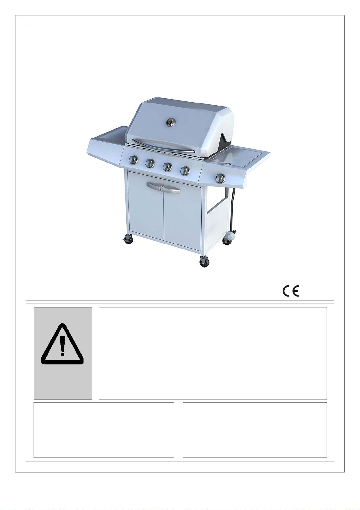
Assembly and Operating Instructions for
4 Burner Stainless Steel Gas BBQ
Photographs are not to scale.
Specifications subject to change
without prior notice.
WARNING
FOR YOUR SAFETY
If you smell gas:
1. Shut off gas to the appliance.
2. Extinguish any open flame.
3. Open barbecue lid or hood.
4. If odour continues, discontinue use and
contact your local dealer.
• For outdoor use only. Not for commercial use.
• Use only Propane regulator 37mbar.
• Read instructions before using the appliance. Failure to follow instructions could
result in death, serious bodily injury, and/or property loss.
• Warning: accessible parts may be very hot. Keep young children away.
• Do not move the appliance during use.
• Turn off the gas supply at the gas bottle after use.
• Any modification of the appliance, misuse, or failure to follow the instructions may
be dangerous and will invalidate your warranty. This does not affect your statutory
rights.
• Retain these instructions for future reference.
• Leak test your barbecue annually. Check the hose connections are tight and leak
test them each time you reconnect the gas bottle.
Model KS10002
1. Do not store or use petrol or other flammable
vapours or liquids in the vicinity of this or any
other appliance.
2. A gas bottle not connected for use shall not be
stored in the vicinity of this or any other
appliance.
0359
FOR YOUR SAFETY

A. Parts List
Quantities vary according to model purchased. Specifications subject to change without prior notice. For more details on
hardware, please see the corresponding Hardware Reference Diagram for your barbecu e model.
Code Part Qty
A1 Grill assembly 1
B1 Warming rack 1
B2 Cooking grill 2
B3 Heat tent 4
B4 Grease cup 1
B5 Grease tray assembly 1
C1 Side burner grate 1
C2 Side burner 1
C3 Side burner electrode 1
C4 Right side burner assembly 1
C5 Side burner knob 1
C6 Left side table assembly 1
C7 Side table panel 1
C8 Side burner panel 1
D1 Left rear leg 1
D2 Left front leg 1
D3 Right rear leg 1
D4 Right front leg 1
D5 Door transom 1
D6 Cart side panel 2
D7 Right front door 1
D8 Left front door 1
D9 Caster 2
D10 Bottom assembly 1
D11 Locking caster 2
E1 M6*12 bolt 30
E2 M6*8 bolt 4
E3 M6 washer 4
E4 Shoulder bolt 2
2
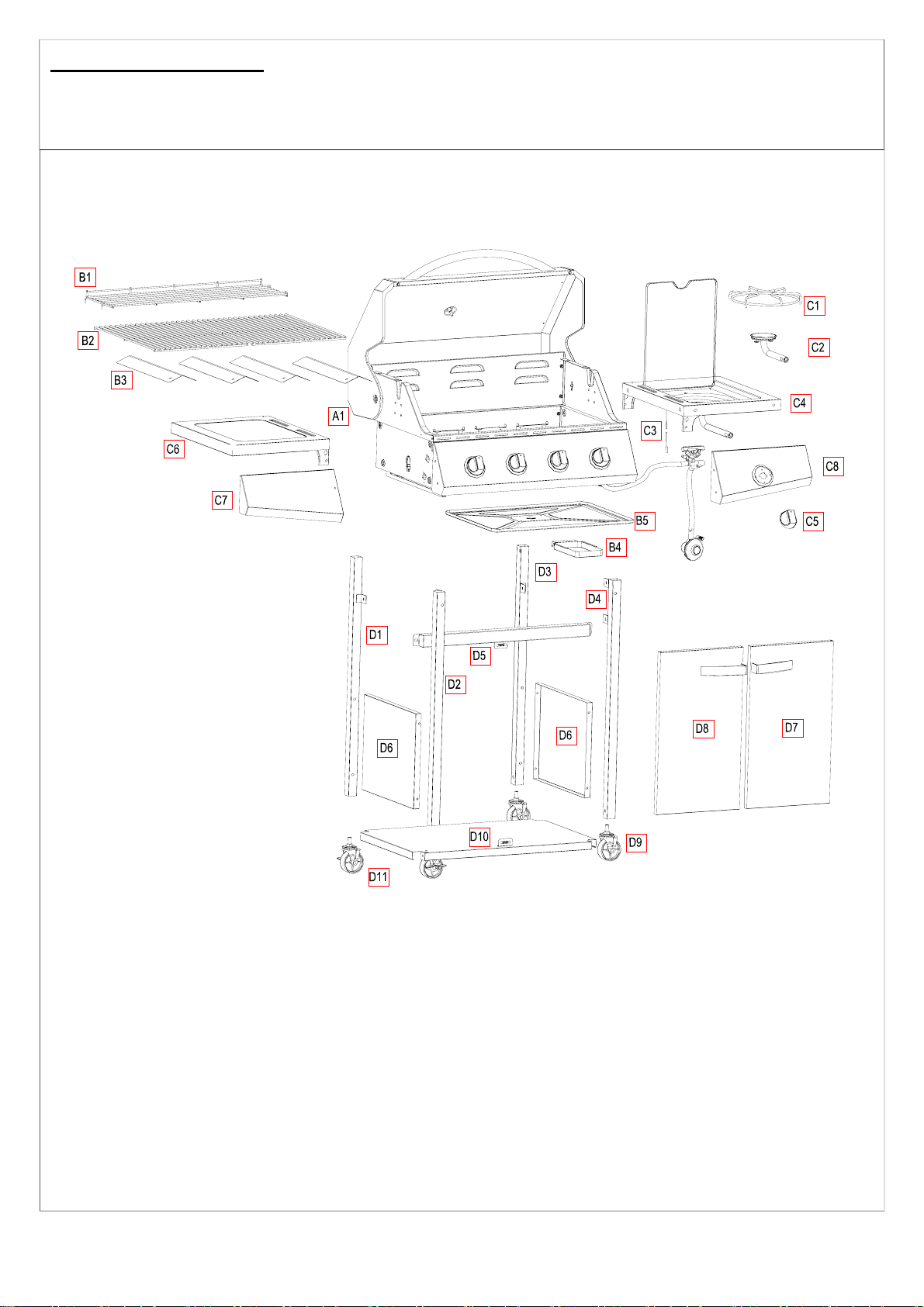
B1. Parts Diagram
Quantities vary according to model purchased. Specifications subject to change without prior notice. For more details on
hardware, please see the corresponding Hardware Reference Diagram for your barbecu e model.
3
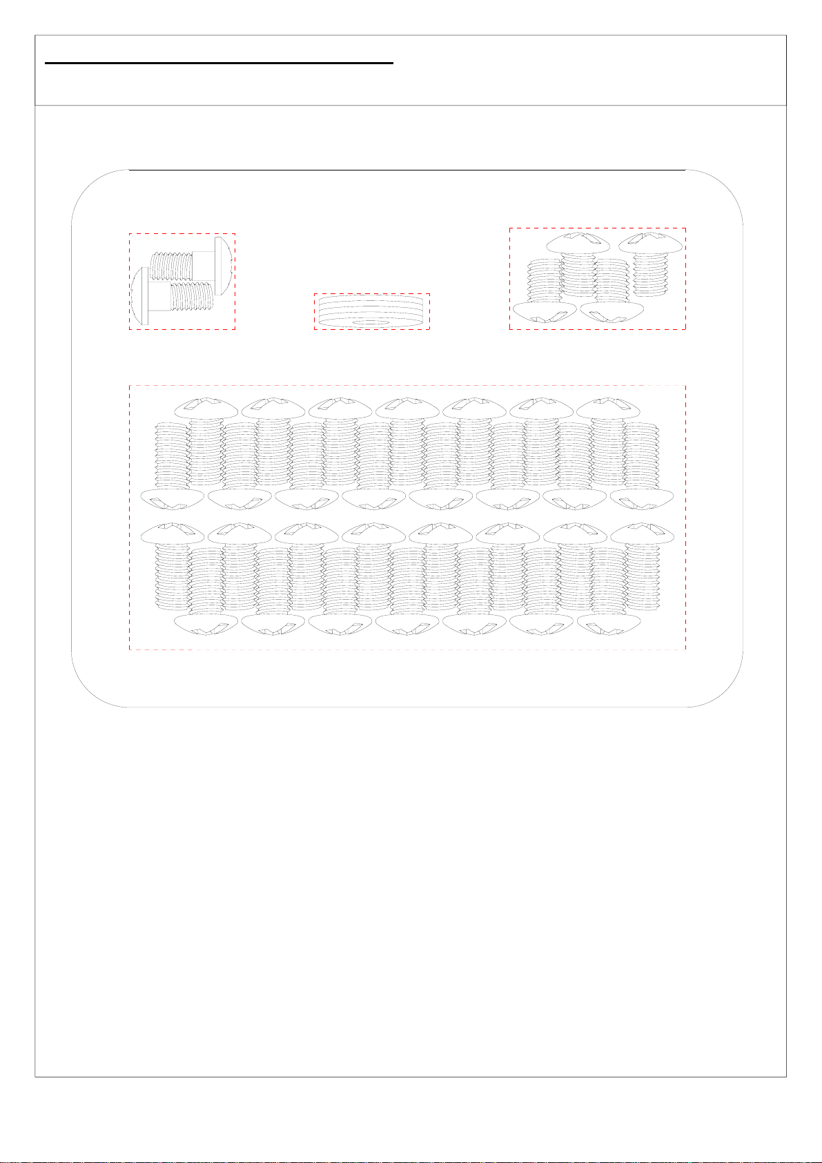
B2. Hardware Reference Diagram
Specifications subject to change without prior notice.
E5 Shoulder
E4 Shoulder Bolt 2PCS
Bolt 2pcs
KS10002
E3 M6 Washer 4PCS
E4 M6 Washer 4PCS
E4 M6 Gaddi 4pcs
E1 M6*12 Bolt 30PCS
E1 M6*12 Bolt 30PCS
E2 M6*8 Bolt 4PCS
E3 M6*8 Bolt 4PCS
KS10002
4
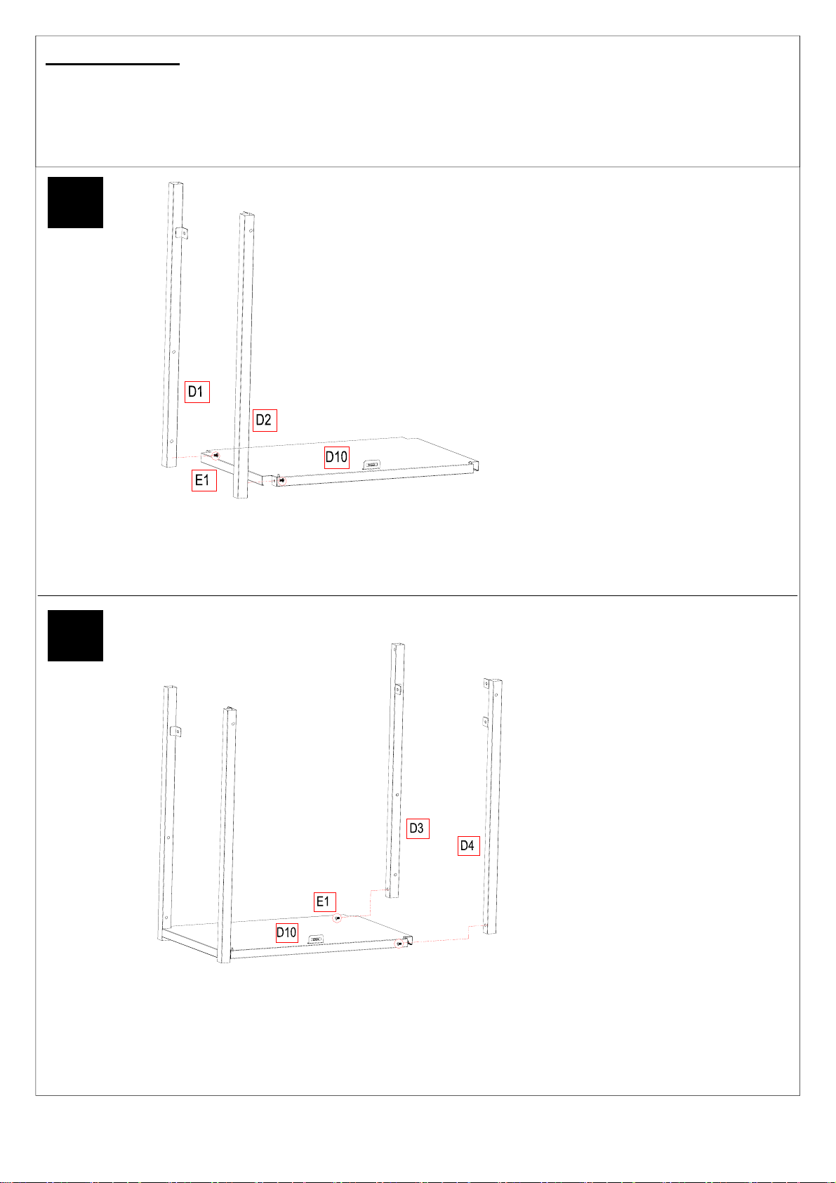
C. Assembly
TOOLS NEEDED FOR ASSEMBLY:
Medium size flat blade or Philips/cross-point screwdriver, adjustable spanner or metric spa nner set.
This barbecue requires two people for assembly. Please remove all packaging materials from all individual parts before
assembling. Please lay out all nuts and bolts and check lengths before assembling. Whilst every care is taken during the
manufacture of this product, care must be taken during the assembly in case sharp edges are present.
1
Fig 1
Put the Left Front Leg (D2) and Left Rear Leg (D1) on the Bottom Assembly (D10) using M6*12 bolts (E1) as
fig 1. Fix the bolts tightly by the screwdriver.
2
Fig 2
Put the Right Front Leg (D4) and Right Rear Leg (D3) on the Bottom Assembly (D10) using M6*12 bolts (E1)
as fig 2.
Fix the bolts tightly by the screwdriver.
5
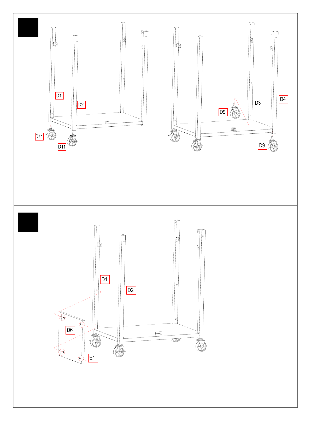
3
Fig 3a
Fix the Locking Casters (D11) to the Left Front Leg (D2) and Left Rear Leg (D1) as fig 3a.
Fix the Casters (D9) to the Right Front Leg (D4) and Right Rear Leg (D3) as fig 3b.
Fig 3b
4
Fig 4
Fix the Cart Side Panel (D6) on the Left Front Leg (D2) and Left Rear Leg (D1) using M6*12 bolts (E1) as fig 4.
Fix the bolts tightly by the screwdriver.
6
 Loading...