

Page 1

Phoenix Professional Audio GmbH
Gewerbepark Conradty 12
D-83059 KOLBERMOOR
Tel. 0049-(0)8031-30425-0
Fax. 0049-(0)8031-30425-25
www.phoenix-pa.com
shop.phoenix-pa.com
info@phoenix-pa.com
„Copyright 2014, Phoenix Professional Audio GmbH, www.phoenix-pa.com“
Phoenix logo is registered at the German Patent- and Trademark Office (TM)
All brands are property of their respective owners.
Made in EU
Instruction manual
ILA-450 Version 010814
Now new with „MLC“-control to correct frequency errors, COMPRESSOR, control
of the loop impedance and SPEAKON output socket.
For systems
according to
EN 60118-4
IEC 118-4
ENGLISH
INDUCTION LOOP AMPLIFIER (LOOP AMPLIFIER) ILA-450
DOC-010814
Page 2

„Copyright 2014, Phoenix Professional Audio GmbH, www.phoenix-pa.com“
Phoenix logo is registered at the German Patent- and Trademark Office (TM)
All brands are property of their respective owners.
Instruction manual
Important safety precautions and symbol explanation
1. Read this manual carefully.
2. Keep this manual well.
3. Consider all warnings.
4. Follow all instructions.
5. ATTENTION: to avoid fires and electric shocks, this system may not be exposed to rain and humidity. Do not use
this device close to any waters.
6. Only clean it with a dry cloth.
7. Do not cover any air vents.
8. Do not put the device close to heat sources like radiators, hot air dampers, ovens or other devices (including am-
plifiers), which emit warmth.
9. Do not override the safety function of the inverse-polarity protection or the safety plug. A plug with inverse-polarity
protection has two pins, and one of them is wider than the other (only for USA/Canada). A safety plug has two pins and
one ground pole. When the included plug does not fit into your socket, the socket is obsolete and has to be replaced
by an electrician.
10. Pass the power cable in a way, that nobody can step onto it and that it cannot be jammed. This is especially valid
for plugs, sockets and the place where the cable comes out of the device.
11. Only use products and accessories specified by Phoenix Professional Audio GmbH.
12. Let maintenance operations only be carried out by qualified maintenance staff. The device has always to be
maintained, when it has been damaged in any way, f.i. when the power cable or the mains plug is damaged, if liquids
have been spilt onto the device or objects have been fallen into it, if the device has been exposed to rain or humidity,
if it does not work normally or if it has been fallen down.
EXPLANATION OF THE GRAPHIC SYMBOLS
The exclamation mark in a triangle shall advise the user of the existence of important
operating- and maintenance instructions in this manual.
The symbol consisting of a flash with an arrowhead in a triangle shall advise the user
of the existence of non-isolated, dangerous voltages within the housing, which can
be strong enough to give an electric shock.
ATTENTION: TO REDUCE THE RISK OF AN ELECTRIC SHOCK, DO NOT REMOVE
THE COVER. USE QUALIFIED STAFF FOR ALL MAINTENANCE OPERATIONS.
2.
Page 3
„Copyright 2014, Phoenix Professional Audio GmbH, www.phoenix-pa.com“
Phoenix logo is registered at the German Patent- and Trademark Office (TM)
All brands are property of their respective owners.
Instruction manual
GENERAL
The new redesigned ILA-450 is a loop amplifier as professional solution for the installation to loop amplifiers.
The ILA-450 loop amplifier for audio transmission is used extensively to supply hearing devices by inductive
audio signals.
The ILA-450 Phoenix induction loop amplifier has been developed as a high quality LOOP-amplifier for
medium induction loops.
The system is characterized particularly easy installation, customer-oriented operation and easy use of the
device at optimum performance.
Induction loop amplifiers are very often used in churches, cinemas, theaters, sales agencies, counters,
interpreter systems or DRIVE IN / DRIVE-THROUGH, so that hearing aid users under difficult acoustic
conditions (background noises, reverberation etc.) can hear much better without disturbing noises.
Advantages of the system:
By the inductive coupling of hearing devices the wanted signal (audio transmission) can be heard much
better without disturbing noises. By the transmission of an audio signal via the induction loop an acceptable
wanted signal/interference signal ratio is reached.
Useful information:
A purely acoustic, direct sound transmission (between speaker and hearing device) by reverberation and
background noises significantly deteriorates the perception of the wanted signal by the hearing device wearer.
Receiver ILA-E:
With the induction loop receiver ILA-E a loop system can be checked or maintained easily, fast and uncomplicated.
The device is especially suitable for responsible staff wherever the induction transmission is installed, or for
people who need a high quality „wireless“ hearing device without hearing aid, f.i. with channel interpreter
systems.
Planning of the loop design:
Not in every place where it would be desirable, acceptable resp. good conditions for installing the induction
loop can be found. Therefore in the planning phase it is necessary to examine a suggested place regarding
the following conditions:
- The magnetic interference fields of electric systems, f.i. heating systems in the floor or the roof area and
the electronic controls of lighting systems (particularly in cinemas, theaters etc.)
- The influence of magnetical or electrically conducting materials in the building structure, particularly in the
place where the loop shall be installed.
- The presence of further induction loops in the neighbourhood, which signals could interfere the planned
loops.
3.
Page 4
„Copyright 2014, Phoenix Professional Audio GmbH, www.phoenix-pa.com“
Phoenix logo is registered at the German Patent- and Trademark Office (TM)
All brands are property of their respective owners.
Instruction manual
GENERAL
Unfortunately it is still common practise to assemble the 100 V power amplifiers with the additional audio
transformer.
Such systems are generally inaccurate as they show a disadvantageous frequency response. Such a system
configuration can increase the inductance with increasing frequency, so the high frequencies which are
important for the speech intelligibility cannot be radiated anymore.
Induction loop amplifiers do not have this disadvantage, therefore they are ideal to produce a constant field
strength by the use of dynamics processors and a special amplifier technology (constant current source).
Control
All important functions of the induction loop amplifier are controlled.
That means the ILA-450 induction loop amplifier controls its internal power amplifier, the functional efficiency of the connected induction loop with a pilot-tone pulse. Should a controlled function fail, the yellow
LED at the front side of the induction loop amplifier does not light and the fault contact „INFO LOOP OK“
[15VDC] will be currentless.
Compatibility according to EN 60118-4:
The most important feature with the redesign was the system compatibility to the standard EN 60118-4, so
a loop assembly based upon a „LOOP-SEGMENT“ system is possible.
In a „LOOP-SEGMENT“ system always two ILA-450 which form a magnetic field work together, thereby
on the entire area always a constant field strength of the magnetic field is reached.
The magnetic field outside the intended area quickly loses strength and drops to ZERO. This is done by
coupling a phase shift FS-1 which is connected between both ILA-450, which in turn produces a signal
phase difference of 90 degrees in the electric current by two adjoining induction loops.
Further instructions for loop installation by using a phase shifter FS-1 are described detailed in the further
chapter.
4.
Page 5
„Copyright 2014, Phoenix Professional Audio GmbH, www.phoenix-pa.com“
Phoenix logo is registered at the German Patent- and Trademark Office (TM)
All brands are property of their respective owners.
Instruction manual
SAFETY INSTRUCTIONS
Before starting the amplifier ILA-450 we ask you to read the safety instructions carefully.
We ask you to carry out the installation according to the following guidelines:
In a clearly visible position a sign „INDUCTIVE COUPLING“ should be placed near the entrance to
the area where an induction loop is installed.
1 - Always put the amplifier onto a smooth and stable surface.
2 - Choose dry surroundings and do not put any liquids onto the amplifier.
3 - Avoid the proximity to heat sources.
4 - Never open the amplifier´s housing without pulling the mains plug out of the socket before.
5 - Only connect the device to 230 VAC mains voltage.
MAIN FEATURES
- Cooling element with a temperature-controlled fan control (internal)
- Short circuit protection - abnormal temperature protection - open circuit protection - overload protection
- LED level display „compressor“
- LED level display „output level“
- LED display loop detector „ERROR“
- LED display system monitoring „PROTECT“
- LED display „system POWER ON“
- SOFT START
- Balanced microphone/line inputs
- INSERT PORT in-/output
- SPEAKON connection for LOOP line
- Phönix connection for LOOP CONTROL
- Separate volume control for all inputs
- Countersunk volume controls, LF/HF-EQ controls
- MLC control at the front side ( „METAL LOSS CORRECTION“)
- Compression LED display 0 to 18 dB
- Output level LED display -12 to 0 dB
- Phantom power for inputs MIC.-1 and MIC.-2 and shiftable phantom power for input MIC./LINE3
- 19“ brackets can be demounted for table version
- Space saving 1 U housing version
- Monitoring of the loop impedance in the range from 0.5 Ohm to 3.0 Ohm
5.
Page 6
Instruction manual
„Copyright 2014, Phoenix Professional Audio GmbH, www.phoenix-pa.com“
Phoenix logo is registered at the German Patent- and Trademark Office (TM)
All brands are property of their respective owners.
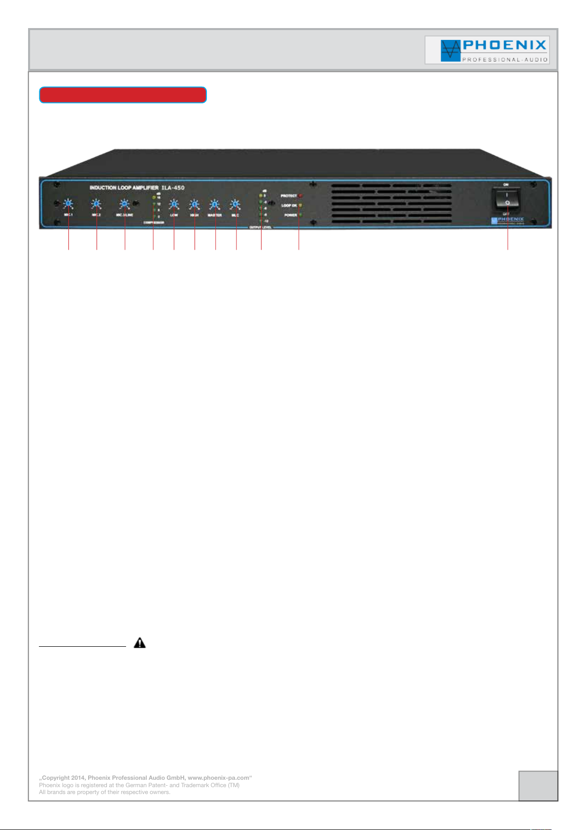
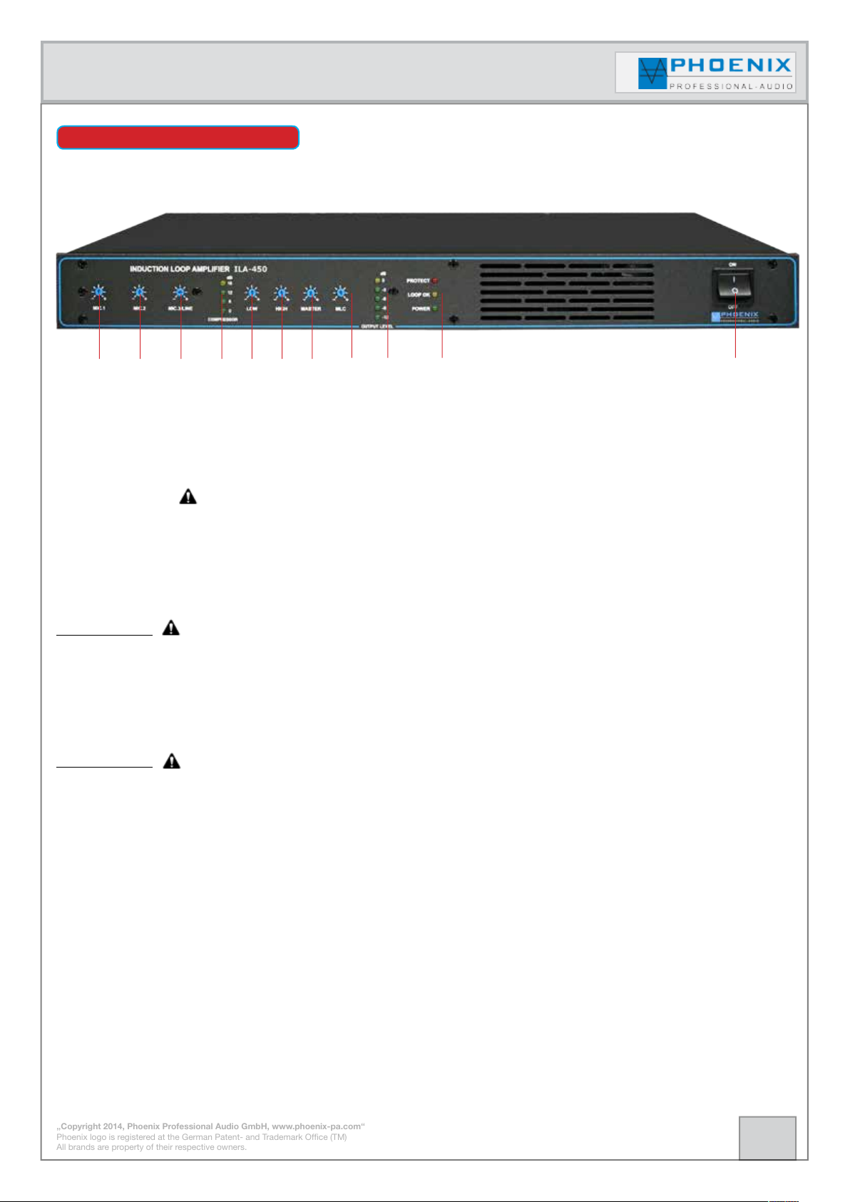
FRONT SIDE
1 2 3 4
5 6
8
7
9 10
1.- MIC.-1
This control determines the sensitivity of the „MIC-1“ input.
2.- MIC.-2
This control determines the sensitivity of the „MIC-2“ input.
3.- MIC.-3/LINE
This control determines the sensitivity of the „MIC.-LINE-3“ input.
4.- COMPRESSOR
LED display (0 dB to 18 dB)
5.- LOW-EQ Filter (+-12dB)
Separate LF-control of the particular microphone- resp. LINE inputs.
Please select the DIP switch for input 3 between MIC.- and LINE sensitivity at the rear side.
6.- HIGH-EQ Filter (+-12dB)
Separate LF-control of the particular microphone- resp. LINE inputs.
Please select the DIP switch for input 3 between MIC.- and LINE sensitivity at the rear side.
11
7.- MASTER
With this control the electrical current flow of the loop can be adjusted.
8.- MLC-„METAL LOSS CORRECTION“
Control to correct frequency response errors which are caused by metals close to the induction loop.
Useful information:
Turn the MLC-control to reach the best tone (audio signal) on the induction loop, simultaneously listen to
the audio signal with ILA-E receiver via the headphones.
Repeat the measurement process for all induction loop amplifiers resp. induction loops ILA-450 which
are bound in the system.
6.
Page 7
Instruction manual
„Copyright 2014, Phoenix Professional Audio GmbH, www.phoenix-pa.com“
Phoenix logo is registered at the German Patent- and Trademark Office (TM)
All brands are property of their respective owners.
FRONT SIDE
1 2 3 4
5 6
8
7
9 10
11
9.- OUTPUT LEVEL
Output level LED display (-12 dB bis 0 dB) shows the current MASTER output level.
10.- PROTECT LOOP OK POWER
System fault indication with red LED.
When the PROTECT control display lights without input signal, possibly there are system oscillations or
other disturbances (f.i. the amplifier´s temperature is too high).
Disconnect the load and reduce the amplification to zero. If the LED continues to light, possibly the amplifier
has to be maintained.
IMPORTANT:
At system FAULT (PROTECT-LED lights) no output level and LOOP OK is displayed!
LOOP OK
Fault indication for loop impedance; should the LED light, the impedance of the induction loop is not within
the measuring range of 0.5 -4.0 Ohm).
IMPORTANT:
After elimination of the fault please always reset the loop amplifier ILA-450 by switching the amplifier off
with the POWER button, wait for 3 seconds and switch it on again with the POWER button.
POWER operation display.
LED lights, LOOP amplifier ILA-450 is activated.
11.- ON/OFF mains switch
7.
Page 8

„Copyright 2014, Phoenix Professional Audio GmbH, www.phoenix-pa.com“
Phoenix logo is registered at the German Patent- and Trademark Office (TM)
All brands are property of their respective owners.
Instruction manual
REAR SIDE/CONNECTIONS
1 2 3 4 5 6 7 8 9 10
1.- MAINS INPUT TERMINAL 230VAC/50-60 Hz
230VAC mains input terminal. Connect the ILA-450 with the power cable to the network.
2.- LOOP CABLE
SPEAKON bush 2-poled, the loop line shall be connected with the clamps (+ Pin) and (- Pin).
3.- LINE OUTPUT [LINE-OUT]
Balanced audio signal output to JACK bush (max. 0 dB).
4.- INSERT
The INSERT bush is unbalanced connected and is used to connect external signal processing equipments
like f.i. additional EQ´s. When the plug is not inserted resp. no additional device is connected with INSERT,
the signal path is interconnected 1 to 1.
5.- AMLIFIER/LOOP CONTROL
Fault indicator output 15VDC, the contact remains isolated when the amplifier and the induction loop work
failure-free. The contact is supplied with 15VDC voltage as long as a system failure or loop failure is present.
6.- DC OUTPUT (+15VDC/-15VDC)
Balanced output voltage +/-15VDC, is used to connect a phase shifter FS-1.
7.- PHANTOM POWER/MIC.-LINE SWITCH
MODE-SWITCH PHANTOM. DIP- (ON) the input MIC.-/LINE 3 is supplied with 12VDC phantom power for
condenser microphones, DIP- (OFF) phantom power is deactivated.
MODE-SWITCH MIC.-LINE. With this switch you determine the sensitivity of the input MIC.-/LINE 3,
switchable between microphone level -50 dB and the line level -10 dB.
Useful information:
Always adjust the correct input sensitivity, otherwise instead of automated system a too high signal
level is reached at the input (position to MIC. and input signal with LINE level), so that the amplifier
cannot process the signal correctly and the signal can be reproduced distorted at the loop output.
8.
Page 9

„Copyright 2014, Phoenix Professional Audio GmbH, www.phoenix-pa.com“
Phoenix logo is registered at the German Patent- and Trademark Office (TM)
All brands are property of their respective owners.
Instruction manual
REAR SIDE/CONNECTORS
1 2 3 4 5 6 7 8 9 10
8.- MIC.-/LINE 3 INPUT
The input is designed balanced (+2), (-3), (1-shielding).
The input sensitivity is adjusted at the device´s front side with separate control MIC.-/LINE 3 and adjusted
by the MODE-SWITCH No. 7.
9.- MIC.2 INPUT
The input is designed balanced +2, -3, 1-shielding. The input sensitivity of the input 2 is adjusted at the
device´s front side with separate control MIC. 2.
10.- MIC.1 INPUT
The input is designed balanced +2, -3, 1-shielding. The input sensitivity of the input 1 is adjusted at the
device´s front side with separate control MIC.1.
Useful information:
Balanced inputs: strip the insulation of the wire liners
for 6 mm and connect them as shown with the clamps.
Tighten the screws firmly.
1 GND
2 +IN
3 -IN
Unbalanced inputs: strip the insulation of the wire liners for
6 mm and connect them as shown with the clamps. The pin
in the middle has to be connected with the screen pin as
shown. Tighten the screws firmly.
1 GND and wire link to 3
2 +IN
9.
Page 10

„Copyright 2014, Phoenix Professional Audio GmbH, www.phoenix-pa.com“
Phoenix logo is registered at the German Patent- and Trademark Office (TM)
All brands are property of their respective owners.
Instruction manual
TECHNICAL APPENDIX
To supply a perfect sound signal also to the users of hearing devices, so-called induction loops are installed.
Herewith the signal is transmitted inductively by a loop passed in the middle of the room into a receiver coil
which is located in the hearing device.
The induction loop has to be passed in a way that it encloses the intended area. The impedance of the loop
is approximately equal to the DC resistance.
When installing the loop into concrete, protective PVC pipe has to be used, IN NO CASE STEEL PIPE.
With difficult structural conditions prior to that a test loop has to be constructed and the supply has to be
checked.
INDICATION:
Directly above the loop wires the reception is worst, as there the flux lines run horizontally.
Cable cross-section
0.5 mm
1.0 mm
1.5 mm
2.5 mm
4.0 mm
2
2
2
2
2
Cable min. length Cable max. length
15 meter 90 meter
30 meter 130 meter
42 meter 160 meter
71 meter 180 meter
115 meter 190 meter
CONSTRUCTION SIMPLE LOOP SYSTEM
A simple induction loop system consists of a LOOP amplifier ILA-450 and one or more induction loops of
the same size, see drawing.
Drawing 1.1 shows single loop Drawing 1.2 shows double loop
ILA-450 LOOP- AMP
ILA-450 LOOP- AMP
10.
Page 11

„Copyright 2014, Phoenix Professional Audio GmbH, www.phoenix-pa.com“
Phoenix logo is registered at the German Patent- and Trademark Office (TM)
All brands are property of their respective owners.
Instruction manual
CONSTRUCTION SIMPLE LOOP SYSTEM
A much better result (constant field strength) than with single loops is achieved by installing „LOOPSEGMENT“ loops. The individual segments have to be of the same size, the distances should be between
2 meters and 5 meters. Examples of use: row of seats in theaters, churchs, schools etc.
IMPORTANT:
Disadvantage of the LOOP-SEGMENT loop without phase shifter is:
Wherever two loop lines run parallel, the field strength is „0“! The area of the „0“-field strength can be
between some centimeters up to one meter.
IMPORTANT:
Rooms and areas where an induction loop is installed, should be marked accordingly.
Please pass parallel lines close together
11.
Page 12

„Copyright 2014, Phoenix Professional Audio GmbH, www.phoenix-pa.com“
Phoenix logo is registered at the German Patent- and Trademark Office (TM)
All brands are property of their respective owners.
Instruction manual
LOOP SYSTEM WITH EXTINCTION OF THE MAGNETIC FIELD
The example shows an induction loop with limitation of the induction field to the side room.
The additional limitation loop is mainly suitable for applications, where a partitioning has been carried out
by f.i. sheetrocks, where two independent variable loops with different audible signals shall be processed.
The length of the limitation loop´s additional winding shall be in the ratio approx. 1:11.
Indications refer to a square room!
IMPORTANT:
Rooms and areas where an induction loop is installed, should be marked accordingly.
12.
Page 13

„Copyright 2014, Phoenix Professional Audio GmbH, www.phoenix-pa.com“
Phoenix logo is registered at the German Patent- and Trademark Office (TM)
All brands are property of their respective owners.
Instruction manual
LOOP SYSTEM WITH 90 DEGREES PHASE SHIFT according to EN 60118-4
The best result (constant field strength) is reached by installation of „DOUBLE LOOP SEGMENT“ with phase
shift. Compatibility according to EN 60118-4.
Such double LOOP SEGMENT induction loops are advisable for large areas and at high influence to the
induction field by metallic objects located in concrete (walls and floors).
Examples of use: big churches, exhibition halls, stations, schools etc.
As the installation of the double LOOP-SEGMENT induction loop takes a lot of time and effort, this kind
of induction loops is usually only possible for new constructions or general refurbishment of the buildings.
Advantage of the double LOOP-SEGMENT induction loop is the up to 4-fold lower loss of the induction
field (low power - large area).
For double LOOP-SEGMENT induction loops the audio signal is connected to the first ILA-450 LOOP
amplifier, which in turn supplies the first loop in the system.
Re
f
Im
By the phase modulation the audio signal is shifted by 90o phases and routed to the second ILA-450, then
the second ILA-450 has to supply the second parallel induction loop in the complete system.
All LOOP segments should have the same size and should not excess areas of 2 up to 5 meters.
Compatibility according to EN 60118-4
In a „LOOP-SEGMENT“ system always two ILA-450 work together, they form a magnetic field, thus on the
complete area always a constant field strength of the magnetic field is reached.
The magnetic field outside the intended area loses quite rapidly strength and drops to ZERO. This is done
by coupling a phase shifter FS-1 which is switched between the two ILA-450, this again produces a signal
phase difference of 90 degrees in the electrical flow by two adjoining induction loops.
13.
Page 14

„Copyright 2014, Phoenix Professional Audio GmbH, www.phoenix-pa.com“
Phoenix logo is registered at the German Patent- and Trademark Office (TM)
All brands are property of their respective owners.
Instruction manual
LOOP SYSTEM WITH 90 DEGREES PHASE SHIFT according to EN 60118-4
Example for a simple LOOP-SEGMENT induction loop system with two ILA-450 (MASTER/SLAVE) and
FS-1 90 degrees phase shifter. It is important that the induction loops are approximately of the same size.
System with single loops
ILA-450 LOOP- AMP
ILA-450 LOOP- AMP
MASTER 0
o
SLAVE 90
o
System with several loops „COMB SYSTEM“
ILA-450 LOOP- AMP
MASTER 0
SLAVE 90
MASTER 0
SLAVE 90
o
o
o
ILA-450 LOOP- AMP
o
14.
Page 15

„Copyright 2014, Phoenix Professional Audio GmbH, www.phoenix-pa.com“
Phoenix logo is registered at the German Patent- and Trademark Office (TM)
All brands are property of their respective owners.
Instruction manual
LOOP SYSTEM WITH 90 DEGREES PHASE SHIFT according to EN 60118-4
Example for a multiple LOOP-SEGMENT induction loop system with (MASTER/SLAVE) configuration, to
cover very large areas with constant magnetic field strength.
Important information:
It is important that the induction loops MASTER and SLAVE are approximately of the same size and have
a width of approx. 50 - 66 % of the loop length.
System component:
4 x ILA-450 induction loop amplifier
1 x FS-1 90
o
phase shifter
ILA-450 LOOP- AMP
ILA-450 LOOP- AMP
MASTER 0
SLAVE 90
MASTER 0
SLAVE 90
o
ILA-450 LOOP- AMP
o
o
ILA-450 LOOP- AMP
o
IMPORTANT:
Rooms and areas where an induction loop is installed, should be marked accordingly.
15.
Page 16

„Copyright 2014, Phoenix Professional Audio GmbH, www.phoenix-pa.com“
Phoenix logo is registered at the German Patent- and Trademark Office (TM)
All brands are property of their respective owners.
Instruction manual
LOOP SYSTEM WITH 90 DEGREES PHASE SHIFT according to EN 60118-4
By the phase modulation the audio signal is shifted by 90o phases and transmitted to the second ILA-450
resp. to the second induction loop.
Then the second ILA-450 has to supply the second parallel induction loop in the complete inductive hearing
device system.
The first LOOP amplifier of the complete circle loop system works without phase shift with 0o.
The first ILA-450 supplies the first parallel induction loop in the complete inductive hearing system.
In a „LOOP-SEGMENT“ system always two ILA-450 work together which form a magnetic field, thus on
the complete area always a constant field strength of the magnetic field is reached.
The magnetic field outside the intended area loses quite rapidly strength and drops to ZERO.
This is done by coupling a phase shifter FS-1 which is switched between the two ILA-450, this again effects
a signal phase difference of 90 degrees in the electrical flow by two adjoining induction loops.
INPUT
FS-1
PHASE SHIFTER
+/-15VDC
ILA-450
MASTER
ILA-450
SLAVE
LOOP 0
o
LOOP 90
o
16.
Page 17

„Copyright 2014, Phoenix Professional Audio GmbH, www.phoenix-pa.com“
Phoenix logo is registered at the German Patent- and Trademark Office (TM)
All brands are property of their respective owners.
Instruction manual
LOOP SYSTEM WITH 90 DEGREES PHASE SHIFT according to EN 60118-4
MASTER 0
FS-1 mains side FS-1 input side
o
OUTPUT „A“
OUTPUT „B“
SLAVE 90
INPUT SIGNAL
o
17.
Page 18

„Copyright 2014, Phoenix Professional Audio GmbH, www.phoenix-pa.com“
Phoenix logo is registered at the German Patent- and Trademark Office (TM)
All brands are property of their respective owners.
Instruction manual
MATHEMATICAL CALCULATION OF THE INDUCTION LOOPS
Calculation of the induction loop type: double LOOP SEGMENT.
1.- First the room length is set (deducting 10-20 cm of the complete length for other installations).
2.- Please set the preferred segment width (between 2 meters and 5 meters depending on the field loss).
3.- Now the coefficient „X“ can be calculated.
„L“= room length
„S“= preferred segment width
From the chart, column „G“ please take the number which is closest to the calculated value „X“.
The coefficient values P 1 and P 2 indicate the number of segments for both loops.
Calculation of the segment width „A“
L
X=
S
L
A=
G
„L“= room length
„G“= number closest to the calculated value „X“
Calculation of the distance between two segments „B“
Calculation of the shif between the two loops „C“
G P 1 P 2
2.6
3.4
4.2
5.0
5.8
6.6
7.4
8.2
9.0
9.8
10.6
11.4
12.2
13.0
13.8
14.6
15.4
16.2
17.0
2
2
3
3
4
4
5
5
6
6
7
7
8
8
9
9
10
10
11
1
2
2
3
3
4
4
5
5
6
6
7
7
8
8
9
9
10
10
B=1,6 x A
B
C=
2
18.
Page 19

„Copyright 2014, Phoenix Professional Audio GmbH, www.phoenix-pa.com“
Phoenix logo is registered at the German Patent- and Trademark Office (TM)
All brands are property of their respective owners.
Instruction manual
MATHEMATICAL CALCULATION OF THE INDUCTION LOOPS
Calculation example:
Room with the dimensions 25 meter x 8.0 meter, the preferred segment width is set to 3.0 meter.
„X“ shall be calculated:
=
=
25
3
25
8,2
=
8,3
=
3,05
(meter)
L
X=
S
From the chart, column „G“ we take a value of 8,2
The coefficient values P 1 and P 2 show:
P 1 =5
P 2 =5
L
„A“ shall be calculated:
Now the exact distance at the beginning of the two loop segments „B“/ „A“ shall be calculated:
A=
G
B=1,6 x A=1,6 x 3,05= 4,88 (meter)
Calculation of the shift between the two loops „C“
G P 1 P 2
2.6
3.4
4.2
5.0
5.8
6.6
7.4
8.2
9.0
9.8
10.6
11.4
12.2
13.0
13.8
14.6
15.4
16.2
17.0
2
2
3
3
4
4
5
5
6
6
7
7
8
8
9
9
10
10
11
1
2
2
3
3
4
4
5
5
6
6
7
7
8
8
9
9
10
10
C=
B
2
=
4,88
=
2
2,44
(meter)
19.
Page 20

„Copyright 2014, Phoenix Professional Audio GmbH, www.phoenix-pa.com“
Phoenix logo is registered at the German Patent- and Trademark Office (TM)
All brands are property of their respective owners.
Instruction manual
MATHEMATICAL CALCULATION OF THE INDUCTION LOOPS
The drawings show the installation of the two calculated induction loops of the calculation example.
Induction loop No. 1 (the first ILA-450)
Induction loop No. 2 (the second ILA-450)
Induction loop „complete“ (the first ILA-450 and the second ILA-450 LOOP amplifier in the system)
20.
Page 21

„Copyright 2014, Phoenix Professional Audio GmbH, www.phoenix-pa.com“
Phoenix logo is registered at the German Patent- and Trademark Office (TM)
All brands are property of their respective owners.
Instruction manual
SCALE DRAWING
The devices have been developed as desktop version and also for 19“-installation.
The suitable 19“-mounting brackets are included in the scope of supply. For details, please refer to the
technical data.
200 mm
443 mm
EQUIPMENT RECEIVER ILA-E
With the induction loop receiver ILA-E a loop system can be supervised or maintained easily, fast and uncomplicated.
The device is especially suitable for responsible staff wherever
the induction transmission is installed, or for people who need a
high quality „wireless“ hearing device without hearing aid, f.i. for
channel interpretation systems.
44 mm(1 U)
21.
Page 22

Instruction manual
„Copyright 2014, Phoenix Professional Audio GmbH, www.phoenix-pa.com“
Phoenix logo is registered at the German Patent- and Trademark Office (TM)
All brands are property of their respective owners.
TECHNICAL DATA
Specifications
Compressor:
Dynamics/Frequency response:
Harmonic distortion:
Loop impedance:
Coverage area:
R.M.S. current (at 1 kHz):
Audio input / outputs:
Audio sensitivity:
Phantom Power:
Info LOOP/AMP CONTROL:
Induction loop measurement: in the range 0.5 - 4.0 Ω
Loop output current/jack:
LOOP output power:
Temperature control: System switch off at 92C
Equalization:
Freq.-correction at LOOP-OUT:
Option:
Protective circuits: Current limiting (short circuit), abnormal temperature protection, soft start.
Voltage supply: 230 VAC - 50/60 Hz
Power:
Indications LEDs: Output level (-12dB to 0dB), Compressor (0 dB to 18 dB), Error, LOOP OK, Power
Dimensions / Colour:
Weight:
ILA-450
automatic (0 dB to 18 dB)
80 Hz - 7.500 kHz (-1.5dB) loop, amplier 20 Hz- 20.000 Hz
< 0.25 %
0.5 - 3.0 Ω
according to the loop version
> 4.5 A
MIC.-1, MIC.-2/LINE, balanced to XLR, INSERT, 0 dB LINE input to JACK
- 50 dB MIK. / -10 dB LINE
shiftable 15 VDC
15 VDC
(PICK@10 A max.), 4A RMS, SPEAKON
P max.180 W
o
, system activation at 60C
LF-EQ/ HF-EQ (+/-12 dB)
o
frequency modulator, receiver ILA-E available
90
(W) 443 mm x (H) 44 mm x (D) 200 mm, graphite, without 19“-mounting brackets
yes, MLC-control
300 VA
approx. 4.5 kg
o
22.
Page 23

Instruction manual
„Copyright 2014, Phoenix Professional Audio GmbH, www.phoenix-pa.com“
Phoenix logo is registered at the German Patent- and Trademark Office (TM)
All brands are property of their respective owners.
23.
 Loading...