

Page 1
ENGLISH
Instruction manual
Phoenix Professional Audio GmbH
Gewerbepark Conradty 12
D-83059 KOLBERMOOR
Tel. 0049-(0)8031-30425-0
Fax. 0049-(0)8031-30425-25
www.phoenix-pa.com
shop.phoenix-pa.com
info@phoenix-pa.com
„Copyright 2016, Phoenix Professional Audio GmbH, www.phoenix-pa.com“
Phoenix logo is registered at the German Patent- and Trademark Office ( TM)
All brands are property of their respective owners.
ILA-1000
DOC-0120216
Made in EU
For systems
according to
EN 60118-4
IEC 118-4
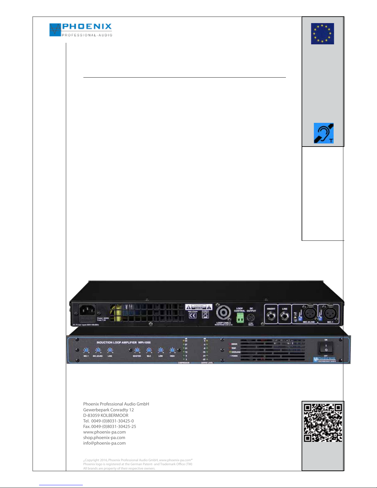
AUTOMATIC INDUCTION LOOP AMPLIFIER ILA-1000
Now new with „MLC“ control to correct frequency errors, COMPRESSOR, control of the
loop impedance and SPEAKON output jack.
Features:
- Digital Automatic audio signal compressor
- Loop detector for the automatic measurement and power adjustment to the loop
impedance.
- Equalization by 2-element LF/HF -EQ
- „MLC“ control to correct frequency errors.
- All control elements are installed countersunk and provide protection against faulty
operations.
Page 2
Instruction manual
1. Read this instruction carefully.
2. Save this instruction well.
3. Consider all warnings.
4. Follow all instructions.
5. ATTENTION: to avoid fires and electric shocks, this system may not be exposed to rain and humidity. Do not use this device
close to waters.
6. Clean it only with a dry cloth.
7. Do not cover any air vents.
8. Do not put it close to heat sources like radiators, hot air dampers, ovens or other devices (including amplifiers) which emit
warmth.
9. Do not override the safety functions of the inverse-polarity protection or safety plug. A plug with inverse-polarity protection
has two pins, and one of them is wider than the other (only for USA/Canada). A safety plug has two pins and one ground pole
(only for USA/Canada). The wide pin or the third pole are intended for your safety. When the supplied plug does not fit into your
socket, the socket is obsolete and has to be replaced by an electrician.
10. Pass the power cable in a way, that nobody can step on it and that it cannot be jammed. This is especially valid for plugs,
sockets and the place where the cable comes out of the device.
11. Only use products and accessories specified by Phoenix Professional Audio GmbH, Inc.
12. Let maintenance operations only be carried out by qualified maintenance staff. The device has always to be maintained if
it has been damaged in any way, f.i. when the power cable or the mains plug is damaged, if liquids have been spilled on the
device or objects have been fallen into it, if the device has been exposed to rain or humidity, if it does not work normally or if
it has been fallen down.
The exclamation mark in a triangle shall advise the user of the existence of important instruction guides and maintenance instructions in this manual.
The symbol consisting of a flash with an arrowhead in a triangle shall advise the user of
the existence of unisolated, dangerous voltages within the housing, which can be strong
enough to give an electric shock.
ATTENTION: TO REDUCE THE RISK OF ELECTRIC SHOCKS, DO NOT REMOVE THE COVER. USE
QUALIFIED STAFF FOR ALL MAINTENANCE OPERATIONS.
Important safety precautions and symbol explanation
EXPLANATION OF THE GRAPHIC SYMBOLS
2.
„Copyright 2016, Phoenix Professional Audio GmbH, www.phoenix-pa.com“
Phoenix logo is registered at the German Patent- and Trademark Office ( TM)
All brands are property of their respective owners.
Page 3
The new redesign ILA-1000 represents a loop amplifier as professional solution for the construction of induction
loops. The ILA-1000 loop amplifier for audio transmission is used on a large scale, to supply hearing devices by
inductive audio signals.
The ILA-1000 automatic induction loop amplifier has been developed as high-quality LOOP amplifier for average
induction loops.
The system is characterized by particularly easy installation, customer-focused operation and easy use of the device
with optimum performance.
Induction loop amplifiers are very often used in churches, cinemas, theatres, sales agencies, libraries, press rooms,
lecture rooms, court rooms, counters, interpreter systems or DRIVE IN / DRIVE-THROUGH, so that wearer of
hearing devices under difficult acoustic conditions (background noises, reverberation etc.) can hear much better
without disturbing noises.
Advantages of the system:
By the inductive coupling of hearing devices, the wanted signal (audio transmission) can be heard much better
without disturbing noises. By the transmission of an audio signal through the induction loop, an acceptable wanted
signal/interfering signal ratio is reached.
Useful information:
A pure acoustic, direct sound transmission (between speaker and hearing device) caused by reverberation and
background noises considerably deteriorates the perception of the wanted signal for the wearer of the hearing device.
Receiver ILA-E:
With the induction loop receiver ILA-E a loop system can be checked or maintained in an easy way, fast and uncomplicated.
The device is especially suitable for responsible staff, wherever the induction transmission is installed, or for people
who need a high-quality „wireless“ hearing devices without hearing aid, f.i. for channel interpreting systems.
Planning of the loop design:
Not anywhere, where it would be desirable, acceptable or good conditions for laying the induction loop can be found.
Therefore it is necessary in the planning phase, to examine a suggested place regarding the following conditions:
- The magnetic interference fields of electrical systems, f.i. heating systems in the floor or in the roof area and the
electronic controls of lighting systems (especially in cinemas, theatres etc.)
- The influence of magnetically or electrically conductive materials in the building structure, especially where the
loop shall be installed.
- The presence of other induction loops in the neighborhood, whose signals could interfere with the signals of the
planned loops.
Instruction manual
GENERAL
„Copyright 2016, Phoenix Professional Audio GmbH, www.phoenix-pa.com“
Phoenix logo is registered at the German Patent- and Trademark Office ( TM)
All brands are property of their respective owners.
3.
Page 4

Instruction manual
GENERAL
„Copyright 2016, Phoenix Professional Audio GmbH, www.phoenix-pa.com“
Phoenix logo is registered at the German Patent- and Trademark Office ( TM)
All brands are property of their respective owners.
Unfortunately it is still the common practice to assemble the 100 V power amplifiers with the additional audio
transformer.
Such systems are fundamentally wrong, as they show an unfavorable frequency response.
Such a system configuration raises the inductance with increasing frequency, so that the high frequencies which
are important for the speech intelligibility cannot be emitted anymore.
Induction loop amplifiers do not have this disadvantage, therefore they are optimally suitable by the use of dynamic
processors and special amplifier technology (constant current source) to produce a constant field strength.
Control
All important functions of the induction loop amplifier are controlled.
That means the ILA-1000 induction loop amplifier controls its internal power final stage, the functional efficiency of
the connected induction loop with a pilot tone pulse. If a controlled function fails, the yellow LED in the amplifier´s
front of the induction loop amplifier does not light and the error contact „INFO LOOP OK“ [15VDC] is currentless.
Compatibility according to EN 60118-4:
The most important attention at the redesign has been put to the compatibility of the system with the norm EN
60118-4, so that a loop structure according to a „LOOP SEGMENT“ system is possible.
In a „LOOP SEGMENT“ system always two ILA-1000 work together which form a magnetic field, thus on the entire
area always the constant field strength of the magnetic field is reached.
The magnetic field outside the intended range loses quite rapidly strength and drops to ZERO. This is done by connecting a phase shifter FS-1 which is switched between the two ILA-1000, which in turn produces a signal phase
difference of 90 degrees in the electrical flow by two adjacent induction loops.
Further instructions for loop laying with use of a phase shifter FS-1 are exactly described in the further chapter.
4.
Page 5
Instruction manual
„Copyright 2016 Phoenix Professional Audio GmbH, www.phoenix-pa.com“
Phoenix logo is registered at the German Patent- and Trademark Office ( TM)
All brands are property of their respective owners.
Before start-up of the amplifier ILA-1000 we ask you to read the safety instructions carefully.
Please carry the installation out according to the following guidelines:
In a clearly visible position close to the entrance to the area where an induction loop is installed, a sign „ INDUCTIVE
COUPLING“ should be fixed.
1 - Always put the amplifier onto a smooth and stable lower surface.
2 - Choose a dry surrounding and do not put any liquids onto the amplifier.
3 - Avoid the closeness to heat sources.
4 - Never open the housing of the amplifier, without pulling the mains plug out of the socket before.
5 - Only connect the device to 230 VAC mains voltage.
SAFETY INSTRUCTIONS
- Cooling element with a temperature-controlled fan control
- Short circuit protection - overheat control - open circuit protection - overload protection
- LED - level indication „compressor“
- LED - level indication „output level“
- LED - indication loop detector „ERROR“
- LED - indication temperature „TEMP“
- LED - indication „OVERLOAD“
- LED - indication „system POWER-ON“
- SOFT START and MEASUREMENT with flashing „POWER LED“
- Balanced microphone/line inputs
- INSERT PORT in-/output
- Phönix connections for LOOP line
- Phönix connections for LOOP CONTROL
- Separate volume control for all inputs
- Countersunk volume controls, LF/HF-EQ control and MLC control at the front side
- Compression LED indication 3 to 33 dB
- Output level LED indication -27 to 0 dB
- Shiftable phantom power (DIP switch at the rear side)
- Shiftable GAIN system (signal increase for +15dB)
- 19“ brackets can be removed for desktop version
- Space-saving 1 U housing version
- Possible loop area 300 m² to 1300m² (depending on loop laying or loop design)
- Control of the loop impedance in the range from 0.5 Ohm to 3.0 Ohm
MAIN FEATURES
5.
Page 6
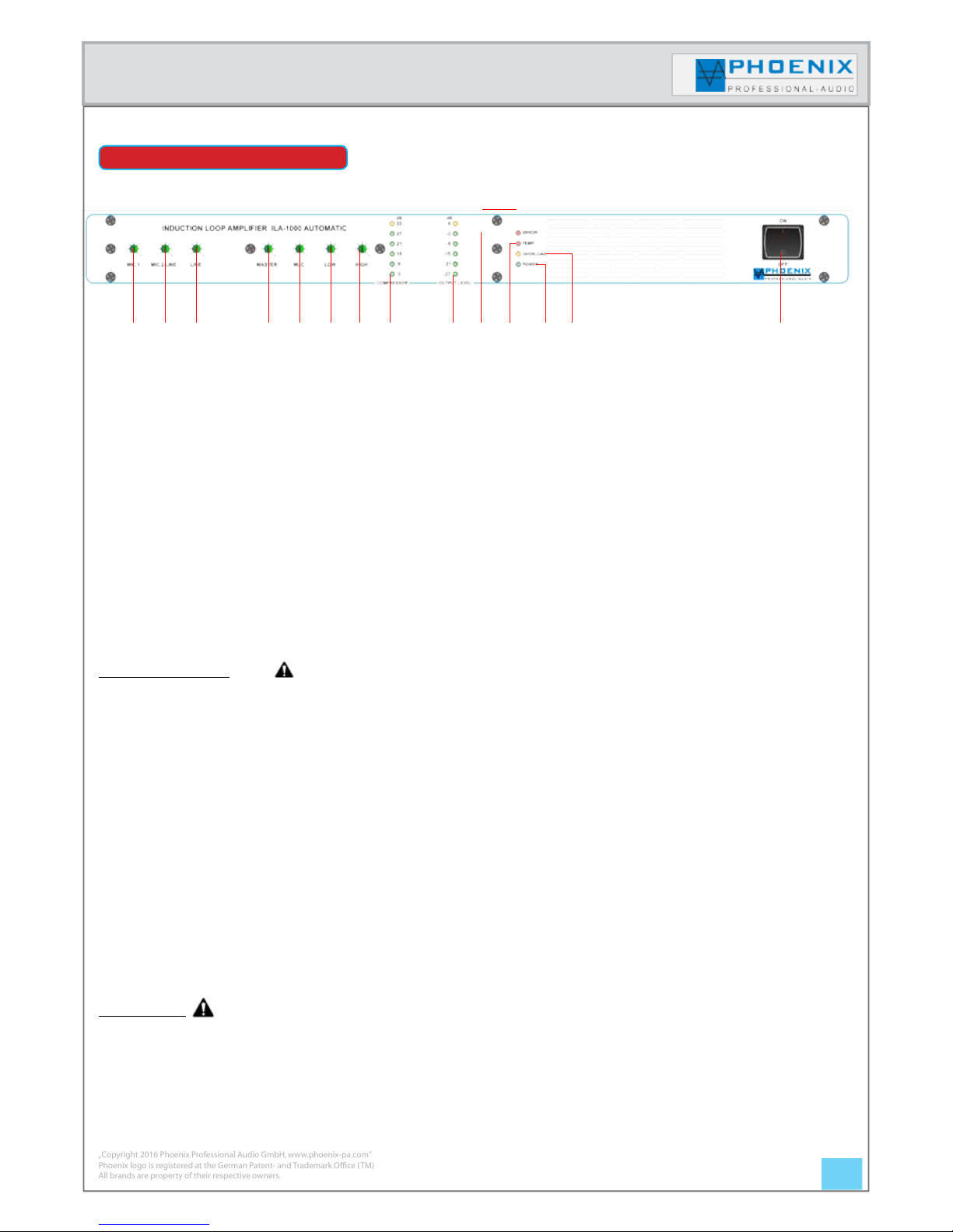
1.- MIC.-1
This control determines the sensitivity (volume) of the „MIC-1“ input.
2.- MIC.-2/ LINE
This control determines the sensitivity (volume) of the „MIC-2/LINE“ input.
3.- LINE
This control determines the sensitivity (volume) of the „LINE“ input.
4.- MASTER
With this control the electrical current flow of the loop can be adjusted.
5.- MLC-„METAL LOSS CORRECTION“
Control to correct frequency response errors which are caused by metals close to the induction loop
Useful information:
Turn the MLC control to reach the best sound (audio signal) on the induction loop, simultaneously listen to the audio
signal with the ILA-E receiver by the headphone.
Repeat the measuring process in all ILA-1000 induction loop amplifiers or induction loops bound in the system.
6.- HIGH-EQ filter (+-12dB)
LF control of the individual microphone- or LINE inputs.
7.- HIGH-EQ filter
HF-EQ control in the range (+/- 12 dB), HF-control of the individual microphone- or LINE inputs.
8.- COMPRESSOR
LED indication (3 dB to 33 dB)
9.- OUTPUT LEVEL
Output level LED indication (-27 dB to 0 dB).
IMPORTANT:
In case of system DISORDER (ERROR LED lights) no output level is indicated!
Instruction manual
FRONT SIDE
„Copyright 2016 Phoenix Professional Audio GmbH, www.phoenix-pa.com“
Phoenix logo is registered at the German Patent- and Trademark Office ( TM)
All brands are property of their respective owners.
1 2 3 4 5 6 7 8 9 10 11 12 13 14
6.
Page 7
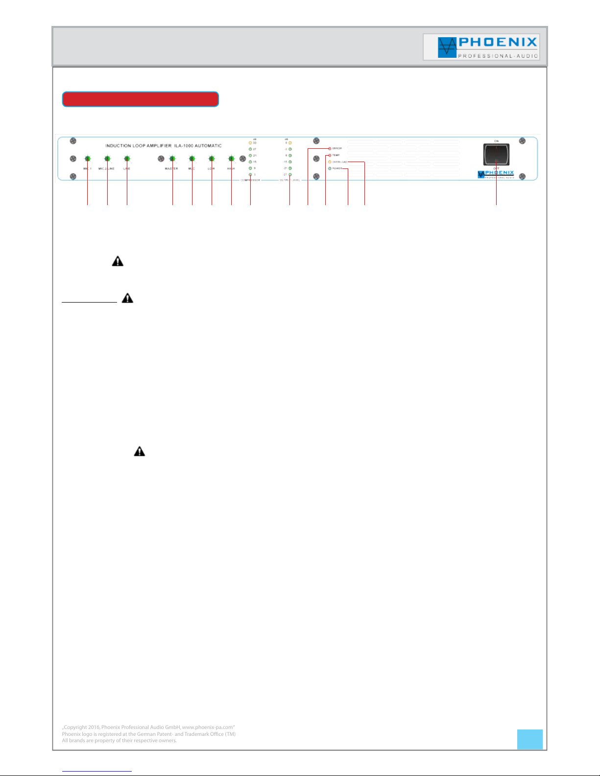
10.- ERROR
Fault indication for loop impedance (impedance is not within the measurement range of 0.5 -3.0 Ohm).
IMPORTANT:
After eliminating the fault please always „reset“ the loop amplifier ILA-1000“ by switching the amplifier off with the
POWER button, wait for 3 sec. and switch it on again with the POWER button.
The measuring cycle (PILOT TONE) is activated again and the POWER LED flashes.
11.- TEMP
Error message indication, the amplifier´s temperature is too high (in this condition the amplifier is deactivated)
12.- POWER operation display
Condition-1 LED flashes, system measurement is carried out and the turn-on delay is active.
Condition-2 LED lights, the system is activated and the measurement of the loop impedance is finished.
13.- OVERLOAD
Overload indication, LED lights or flashes when an overload is measured, the LIMITER is activated.
14.- ON/OFF - mains switch
Instruction manual
„Copyright 2016, Phoenix Professional Audio GmbH, www.phoenix-pa.com“
Phoenix logo is registered at the German Patent- and Trademark Office ( TM)
All brands are property of their respective owners.
FRONT SIDE
1 2 3 4 5 6 7 8 9 10 11 12 13 14
7.
Page 8

1.- LOOP CABLE
SPEAKON jack 2-poled, the loop line shall be connected to the clamps (+ Pin) and (- Pin).
2.- AMLIFIER/LOOP CONTROL
Fault indicator output 15VDC, the contact remains isolated when the amplifier and the induction loop work failurefree. The contact is supplied with 15VDC voltage, as long as a system failure or loop error is present.
3.- DC OUTPUT (+15VDC/-15VDC)
Balanced output voltage +/-15VDC, is used for connection or power supply of a phase shifter FS-1.
4.- INSERT
The INSERT jack is unbalanced connected, it is used to connect external processing devices like f.i. additional EQ´s
or FS-1 phase shifter. When the plug is not plugged in or no accessory device is connected with INSERT, the signal
path is interconnected 1 to 1.
5.- LINE OUTPUT [LINE-OUT]
Balanced audio signal output to JACK bush (max. 0 dB).
6.- MODE-SWITCH MIC.-LINE
With this switch you determine the sensitivity of the input MIC.2/LINE. Shiftable between microphone and line level.
Attention:
Always adjust the correct input sensitivity, otherwise in spite of automatic device a too high signal level is reached
at the input (position to MIC. and input signal with LINE level), so that the amplifier cannot properly process the
signal and the signal can be reproduced distorted at the loop output.
Instruction manual
REAR SIDE/CONNECTIONS
1 2 3 4 5 6 7 8 9
„Copyright 2016, Phoenix Professional Audio GmbH, www.phoenix-pa.com“
Phoenix logo is registered at the German Patent- and Trademark Office ( TM)
All brands are property of their respective owners.
10
8.
Page 9

7.- SWITCH/DIP switch GAIN/PHANTOM
DIP-1 (ON) the sensitivity of the input is raised for +15 dB
DIP-1 (OFF) standard sensitivity of the input is adjusted
DIP-2 (ON) the input MIC.-2/LINE is supplied with 15VDC phantom power for condenser microphones
DIP-2 (OFF) the phantom power is deactivated.
8.- MIC.2/LINE INPUT
The input is designed balanced (+2), (-3), (1-shielding) (see drawing).
The input sensitivity is adjusted at the device´s front side with separate control MIC.2/LINE and by DIP-1 or MODE
SWITCH.
MODE-SWITCH MIC.-LINE
With this switch you determine the sensitivity of the input MIC.2/LINE between microphone and line level.
DIP-1 (ON) the sensitivity of the input is raised for +15 dB.
DIP-1 (OFF) standard sensitivity of the input is adjusted.
ATTENTION
All XLR inputs have a shiftable phantom power 15VDC, DIP-2 (ON-position). If unbalanced, dynamic microphones
shall be connected to the audio inputs, a coupling condenser has to be added or the phantom power has to be
switched off, DIP-2 (OFF-position).
Instruction manual
„Copyright 2016 Phoenix Professional Audio GmbH, www.phoenix-pa.com“
Phoenix logo is registered at the German Patent- and Trademark Office ( TM)
All brands are property of their respective owners.
REAR SIDE/CONNECTIONS
1 2 3 4 5 6 7 8 9 10
Unbalanced inputs: isolate the wire lines for 6 mm and connect
them as shown with the clamps. The pin in the middle has to be
connected with the shielding pin as shown. Tighten the screws
firmly.
1 GND
2 +IN
3 -IN
1 GND and wire link to 3
2 +IN
Balanced inputs: isolate the wire lines for 6 mm and connect
them as shown with the clamps. Tighten the screws firmly.
9.
Page 10

Instruction manual
„Copyright 2016 Phoenix Professional Audio GmbH, www.phoenix-pa.com“
Phoenix logo is registered at the German Patent- and Trademark Office ( TM)
All brands are property of their respective owners.
REAR SIDE/CONNECTORS
1 2 3 4 5 6 7 8 9 10
9.- SWITCH/ DIP switch GAIN/PHANTOM
DIP-1 (ON) the sensitivity of the input is increased for +15 dB
DIP-1 (OFF) standard sensitivity of the input is adjusted
DIP-2 (ON) the input MIC.-2/LINE is supplied with 15VDC phantom power for condenser microphones
DIP-2 (OFF) the phantom power is deactivated.
10.- MIC.1 INPUT
The input is designed balanced (+2), (-3), (1-shielding) (see drawing).
The input sensitivity is adjusted at the device´s front side with separate control MIC.2/LINE and by DIP-1 or MODESWITCH.
ATTENTION
All XLR inputs have a shiftable phantom power 15VDC, DIP-2 (ON-position). If unbalanced, dynamic microphones
shall be connected to the audio inputs, a coupling condenser has to be added or the phantom power has to be
switched off DIP-2 (OFF-position).
10.
Page 11

Instruction manual
„Copyright 2016, Phoenix Professional Audio GmbH, www.phoenix-pa.com“
Phoenix logo is registered at the German Patent- and Trademark Office ( TM)
All brands are property of their respective owners.
TECHNICAL ATTACHMENT
To provide a perfect sound signal also for users of hearing devices, so-called induction loops are laid. Here the signal
is transferred inductively by means of a loop laid in the room into a receiver coil located in the hearing device.
The induction loop has to be laid in a way, that it encloses the intended effective area. The impedance of the loop is
approximately equal to the DC resistance.
When laying the loop in concrete, PVC conduit has to be used, IN NO CASE STEEL TUBE.
In case of difficult structural conditions, previously a test loop has to be laid out and the supply has to be checked.
NOTE:
Directly above the loop wires the reception is worst, as the field lines run horizontally there.
Line cross-section
Line min. length Line max. length
0.5 mm
2
15 meter 90 meter
1.0 mm
2
30 meter 130 meter
1.5 mm
2
42 meter 160 meter
2.5 mm
2
71 meter 180 meter
4.0 mm
2
115 meter 190 meter
CONSTRUCTION EASY LOOP SYSTEM „Single Array System“
An easy induction loop system consists of a LOOP amplifier ILA-1000 and one or more induction loops of the same
size, see drawing.
ILA1000 LOOP- AMP
ILA-1000 LOOP- AMP
Illustration 1.1 shows single loop according to DIN EN 60118-4 Illustration 1.2 shows double loop according to DIN EN 60118-4
11.
Page 12

Instruction manual
„Copyright 2016, Phoenix Professional Audio GmbH, www.phoenix-pa.com“
Phoenix logo is registered at the German Patent- and Trademark Office ( TM)
All brands are property of their respective owners.
Please lead parallel lines close together
A significantly better result (constant field strength) than in single loops is reached by the laying of „LOOP-SEGMENT“
loops. The individual segments have to be of the same size, the distances should be between 2 meters and 5 meters.
Application example: Tiers in theaters, churches, schools etc.
IMPORTANT:
The disadvantage of the LOOP-SEGMENT loop without phase shifter is:
Wherever two loop lines are parallel, the field strength is equal to „0“! The area of the „0“-field strength can be between
some centimeters up to one meter.
IMPORTANT:
Rooms and areas where an induction loop is laid, should be marked accordingly.
CONSTRUCTION EASY LOOP SYSTEM „Single Array System“
12.
Page 13

Instruction manual
„Copyright 2016, Phoenix Professional Audio GmbH, www.phoenix-pa.com“
Phoenix logo is registered at the German Patent- and Trademark Office ( TM)
All brands are property of their respective owners.
The example shows an induction loop with limitation of the induction field to the side room.
The additional limitation loop is suitable mainly for applications, where a partitioning by f.i. sheetrocks has been
carried out, or where two independent variable loops with different auditory signals shall be processed.
The length of the additional turn of the limitation loop shall be in the ratio of about 1:11.
The indications refer to a square room!
IMPORTANT:
Rooms and areas, in which an induction loop is laid, should be marked accordingly.
LOOP SYSTEM WITH EXTINCTION OF THE MAGNETIC FIELD
13.
Page 14

Instruction manual
„Copyright 2016, Phoenix Professional Audio GmbH, www.phoenix-pa.com“
Phoenix logo is registered at the German Patent- and Trademark Office ( TM)
All brands are property of their respective owners.
The best result (a constant field strength) is reached by laying „DOUBLE LOOP SEGMENT“ with phase shift.
Compatibility according to EN 60118-4.
Such double LOOP-SEGMENT induction loops are recommended for large areas and large induction field influence
by metallic objects located in concrete (walls and floors).
Application examples: big churches, exhibition halls, stations, schools, gyms etc.
Since the laying of the double LOOP-SEGMENT induction loop involves rather high costs, this kind of induction loops
is usually only possible for new buildings or major overhaul of the buildings.
The advantage of the double LOOP-SEGMENT induction loop is the up to 4-fold lower loss of the induction field
(low power - large area).
For double LOOP-SEGMENT induction loops, the audio signal is connected to the first ILA-1000 LOOP amplifier, this
in turn supplies the first loop in the system.
By the phase modulation the audio signal is shifted by 90o phases and transferred to the second ILA-1000, then the
second ILA-1000 has to supply the second parallel induction loop in the whole system.
All LOOP segments should be equal and not exceed areas from 2 up to 5 meters.
Compatibility according to EN 60118-4
In a „LOOP-SEGMENT“ system always two ILA-1000 work together which form a magnetic field, thereby on the
entire area always the constant field strength of the magnetic field is reached.
The magnetic field outside the intended area quite rapidly loses strength and drops to ZERO. This is done by coupling a phase shifter FS-1, which is switched between the two ILA-1000, this in turn generates a signal phase difference of 90 degrees in the electrical flow by two adjacent induction loops.
LOOP SYSTEM WITH 90 DEGREES PHASE SHIFT according to EN 60118-4
f
Re
Im
14.
Phased Array System
Page 15

Instruction manual
„Copyright 2016 Phoenix Professional Audio GmbH, www.phoenix-pa.com“
Phoenix logo is registered at the German Patent- and Trademark Office ( TM)
All brands are property of their respective owners.
LOOP SYSTEM MIT 90 DEGREES PHASE SHIFT according to EN 60118-4
Example for an easy LOOP-SEGMENT induction loop system with two ILA-1000 (MASTER/SLAVE) and FS-1 90 degrees phase shift. It is important that the induction loops are approximately the same size.
ILA-1000 LOOP- AMP
ILA-1000LOOP- AMP
MASTER 0
o
SLAVE 90
o
System with single loops
System with multiple loops „COMB SYSTEM“
ILA-1000 LOOP- AMP
ILA-1000 LOOP- AMP
MASTER 0
o
SLAVE 90
o
MASTER 0
o
SLAVE 90
o
15.
Phased Array System
Page 16

Instruction manual
„Copyright 2016, Phoenix Professional Audio GmbH, www.phoenix-pa.com“
Phoenix logo is registered at the German Patent- and Trademark Office ( TM)
All brands are property of their respective owners.
LOOP SYSTEM WITH 90 DEGREES PHASE SHIFT according to EN 60118-4
Example for a multiple LOOP-SEGMENT induction loop system with (MASTER/SLAVE) configuration, to cover very
large areas with constant magnetic field strength.
Important information:
It is important that the induction loops MASTER and SLAVE are approximately the same size and have a width of of
about 50 - 66 % of the loop length.
System component:
4 x ILA-1000 induction loop amplifier
2 x FS-1 90o phase shift
ILA-1000 LOOP- AMP
ILA-1000 LOOP- AMP
ILA-1000 LOOP- AMP
ILA-1000LOOP- AMP
MASTER 0
o
SLAVE 90
o
SLAVE 90
o
MASTER 0
o
IMPORTANT:
Rooms and areas, in which an induction loop is laid, should be marked accordingly.
16.
Phased Array System
Page 17

Instruction manual
„Copyright 2016, Phoenix Professional Audio GmbH, www.phoenix-pa.com“
Phoenix logo is registered at the German Patent- and Trademark Office ( TM)
All brands are property of their respective owners.
LOOP SYSTEM WITH 90 DEGREES PHASE SHIFT according to EN 60118-4
By the phase modulation the audio signal is shifted for 90o phases and transferred to the second ILA-1000 or to the
second induction loop.
Then the second ILA-1000 has to supply the second plumper induction loop in the whole inductive hearing system.
The first LOOP amplifier of the whole ring loop system works without phase shift with 0o.
The first ILA-1000 supplies the first plumper induction loop in the whole inductive hearing system.
In a „LOOP-SEGMENT“ system always two ILA-1000 work together which form a magnetic field, thereby on the entire area always the uniform field strength of the magnetic field is reached.
The magnetic field outside the intended area quite rapidly loses strength and drops to ZERO.
This is done by coupling a phase shifter FS-1 which is switched between the two ILA-1000, which in turn causes a
signal phase difference of 90 degrees in the electrical flow by two adjacent induction loops.
LOOP 0
o
LOOP 90
o
ILA-1000
MASTER
ILA-1000
SLAVE
FS-1
PHASE SHIFTER
AUDIO
INPUT
+/-15VDC
INSERT
INSERT
INSERT „A“
INSERT „B“
17.
Phased Array System
Page 18

Instruction manual
„Copyright 2016, Phoenix Professional Audio GmbH, www.phoenix-pa.com“
Phoenix logo is registered at the German Patent- and Trademark Office ( TM)
All brands are property of their respective owners.
LOOP SYSTEM WITH 90 DEGREES PHASE SHIFT according to EN 60118-4
MASTER 0
o
SLAVE 90
o
FS-1 mains side
SIGNAL INPUT
18.
Phased Array System
Page 19

Instruction manual
„Copyright 2016, Phoenix Professional Audio GmbH, www.phoenix-pa.com“
Phoenix logo is registered at the German Patent- and Trademark Office ( TM)
All brands are property of their respective owners.
MATHEMATICAL CALCULATION OF THE INDUCTION LOOPS
Calculation of the induction loop type: double LOOP SEGMENT.
1.- At first the room length is set (deducting 10-20 cm of the total lengths for other installations).
2.- Please set the favoured segment width (between 2 meters and 5 meter, depending on the field loss).
3.- Now the coefficient „X“ can be calculated.
„L“= room length
„S“= favoured segment width
From the chart, column „G“ please take the number which is next to the calculated value „X“.
The coefficient values P 1 and P 2 indicate the numbers of segments for both loops.
Calculation of the segment width „A“
„L“= room length
„G“= number next to the calculated value „X“
Calculation of the distance between two segments „B“
Calculation of the shift between the two loops „C“
X=
L
S
A=
L
G
B=1,6 x A
C=
B
2
2.6
3.4
4.2
5.0
5.8
6.6
7.4
8.2
9.0
9.8
10.6
11.4
12.2
13.0
13.8
14.6
15.4
16.2
17.0
2
2
3
3
4
4
5
5
6
6
7
7
8
8
9
9
10
10
11
1
2
2
3
3
4
4
5
5
6
6
7
7
8
8
9
9
10
10
G P 1 P 2
19.
Page 20

Instruction manual
„Copyright 2016, Phoenix Professional Audio GmbH, www.phoenix-pa.com“
Phoenix logo is registered at the German Patent- and Trademark Office ( TM)
All brands are property of their respective owners.
Calculation example:
Room with the dimension 25 meter x 8.0 meter, the favoured segment width is set to 3.0 meter.
„X“ shall be calculated:
From the chart, column „G“ we take a value of 8,2
The coefficient values P 1 and P 2 show:
P 1 =5
P 2 =5
„A“ shall be calculated:
Now the exact distance at the beginning of the two loop segments „B“/ „A“ shall be calculated:
Calculation of the shift between the two loops „C“
X=
L
S
=
25
3
=
8,3
A=
L
G
=
25
8,2
=
3,05
(meter)
B=1,6 x A=1,6 x 3,05= 4,88 (meter)
C=
B
2
=
4,88
2
=
2,44
(meter)
2.6
3.4
4.2
5.0
5.8
6.6
7.4
8.2
9.0
9.8
10.6
11.4
12.2
13.0
13.8
14.6
15.4
16.2
17.0
2
2
3
3
4
4
5
5
6
6
7
7
8
8
9
9
10
10
11
1
2
2
3
3
4
4
5
5
6
6
7
7
8
8
9
9
10
10
G P 1 P 2
MATHEMATICAL CALCULATION OF THE INDUCTION LOOPS
20.
Page 21

Instruction manual
The drawings show the laying of the two calculated induction loops from the example calculation.
Induction loop No. 1 (the first ILA-1000)
Induction loop No. 2 (the second ILA-1000)
Induction loop „total“ (the first ILA-1000 and the second ILA-1000 LOOP amplifier in the system)
MATHEMATICAL CALCULATION OF THE INDUCTION LOOPS
21.
Page 22

Instruction manual
„Copyright 2016, Phoenix Professional Audio GmbH, www.phoenix-pa.com“
Phoenix logo is registered at the German Patent- and Trademark Office ( TM)
All brands are property of their respective owners.
DIMENSIONAL DRAWING
443 mm
200 mm
44 mm (1 U)
The devices have been developed to be suitable as desktop version as well as for 19“-mounting.
The suitable 19“ mounting brackets are included in the scope of supply. For more details please see the technical data.
ACCESSORY: RECEIVER ILA-E
With the induction loop receiver ILA-E, a loop system can be checked
or maintained easily, fast and uncomplicated.
The device is especially suitable for responsible staff, wherever the
induction transmission is installed, or for people who need a highquality „wireless“ hearing device without hearing aid, f.i. for channel
interpreter systems.
22.
Page 23

Instruction manual
„Copyright 2016, Phoenix Professional Audio GmbH, www.phoenix-pa.com“
Phoenix logo is registered at the German Patent- and Trademark Office ( TM)
All brands are property of their respective owners.
Compressor / limiter:
Dynamic/frequency response:
Loop impedance:
Coverage area:
Harmonic distortion:
Audio inputs / outputs:
Automatic (3 dB to 33 dB)
Audio sensitivity:
Phantom power:
Info LOOP/AMP CONTROL:
Induction loop measurement: in the range 0.5 - 3.0 Ω
80 Hz - 7 kHz (-1.5 dB)
0.5 - 3.0 Ω
to approx. 1300 m
2
depending on the loop design
> 9.4 A
- 50/-70 dB MIC. / 0 dB LINE
shiftable 15 VDC
28VDC/2A, 125VAC/0.5A
Equalization:
Freqency correction at LOOP-OUT:
ILA-1000
Loop output current:
< 0.25 %
MIC.-1, MIC.-2/LINE, balanced to XLR, INSERT, 0 dB LINE input to JACK
Technische Daten
Effective power (at 1 kHz):
automatic adaption to the LOOP impedance (9.4 A max.)
LOOP output power:
P max.135 W
Temperature control: System switch off at 92C
o
, system activation at 60C
o
LF-EQ/ HF-EQ (+/-12 dB)
yes, MLC control
Protective circuits: Current limiting (short circuit), excess temperature protection, soft start
Dimensions / Colour:
Weight:
Voltage supply: 230 VAC - 50/60 Hz
Power:
200 VA
Indications LEDs: Overload, Output Level (-27 dB to 0 dB), Compressor (3 dB to 33 dB), Error, Temp, Power
(W) 443 mm x (H) 44 mm x (D) 200 mm, graphite, without 19“ mounting brackets
approx. 5.0 kg
Option:
90
o
frequency modulator, receiver ILA-E available
Operating time:
Battery:
Weight:
Indication / measurement LED:
ILA-E
Headphones:
100 hours
GREEN: 50mW, YELLOW: 100mW, RED: 400 mW [M/RMS]
Material:
plastic
Colour:
black
2 x 1,5 V type: AA or rechargeable batteries
200 Ohm, 3,5 mm mini jack plug
100 g (without battery)
W = 67 mm H = 90 mm D = 25 mm
Dimensions:
Specifications
THD:
Frequency response with CUT filter:
400 Hz to 6 kHz, +/- 3 dB
Headphone output:
100 mW@200 Ohm
better than 0.5%@1 kHz
85 Hz to 6 kHz, +/- 0.5 dB
Frequency response without CUT filter:
SPECIFICATIONS
23.
Liability exclusion
The author points out that the illustrations, explanations, calculations etc. which are contained in the guideline only have exemplary character.
They reflect the present state of knowledge and the current legal status, but do not claim to be complete. Given the complexity
of projects, the development of individual, related to the respective project solutions, is essential. A liability for all descriptions,
applications, indications and transfers - also partly - of the guideline or individual information is hereby expressly excluded.
Important information
For all pages of this manual is valid:
Technical changes and printed errors preserved.
The illustrations are similar, color variations preserved.
 Loading...