

Phoenix DryRod 300/120+, DryRod 300/120-240, DryRod 300ST/120, DryRod 300/240-480, DryRod 300ST/120-240 Operating Instructions Manual
...Page 1
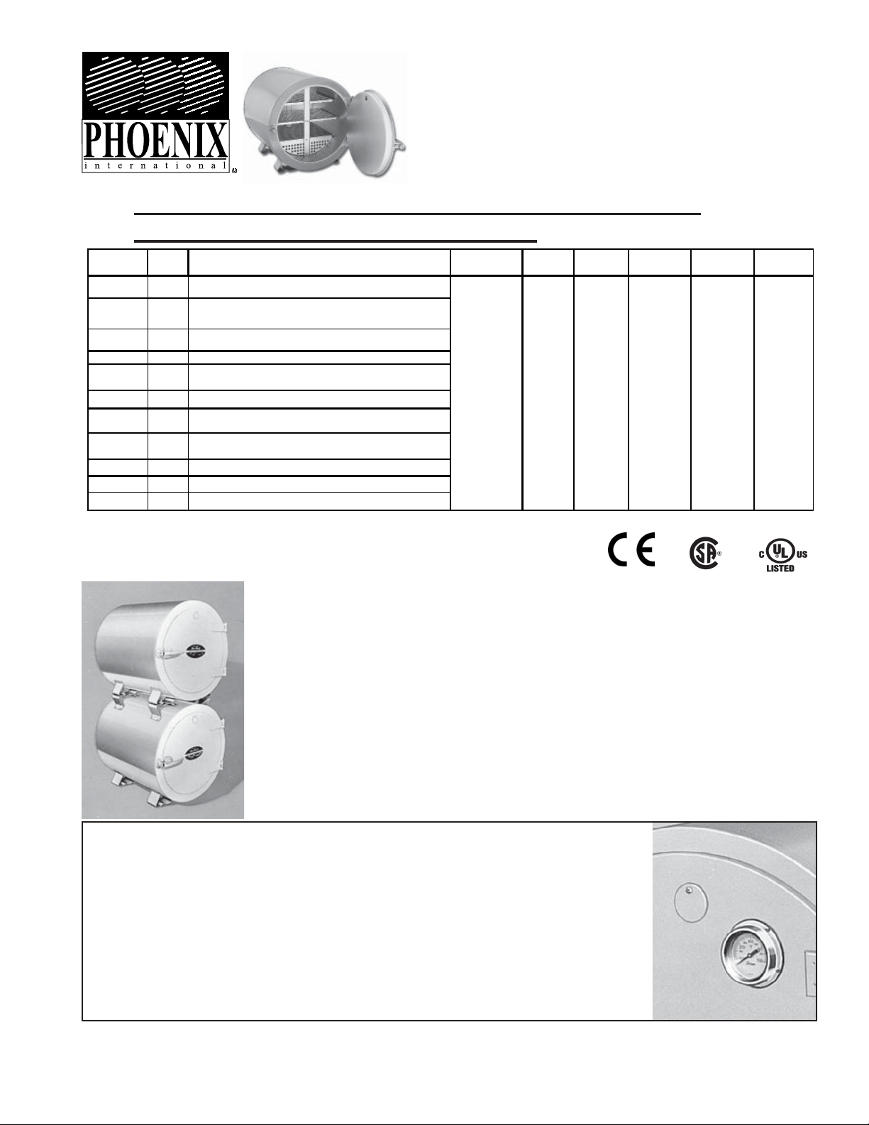
Electrode Stabilizing
DryRod
Ovens
I. OPERATING INSTRUCTIONS FOR TYPE 300 SERIES
ELECTRODE STABILIZATION OVENS
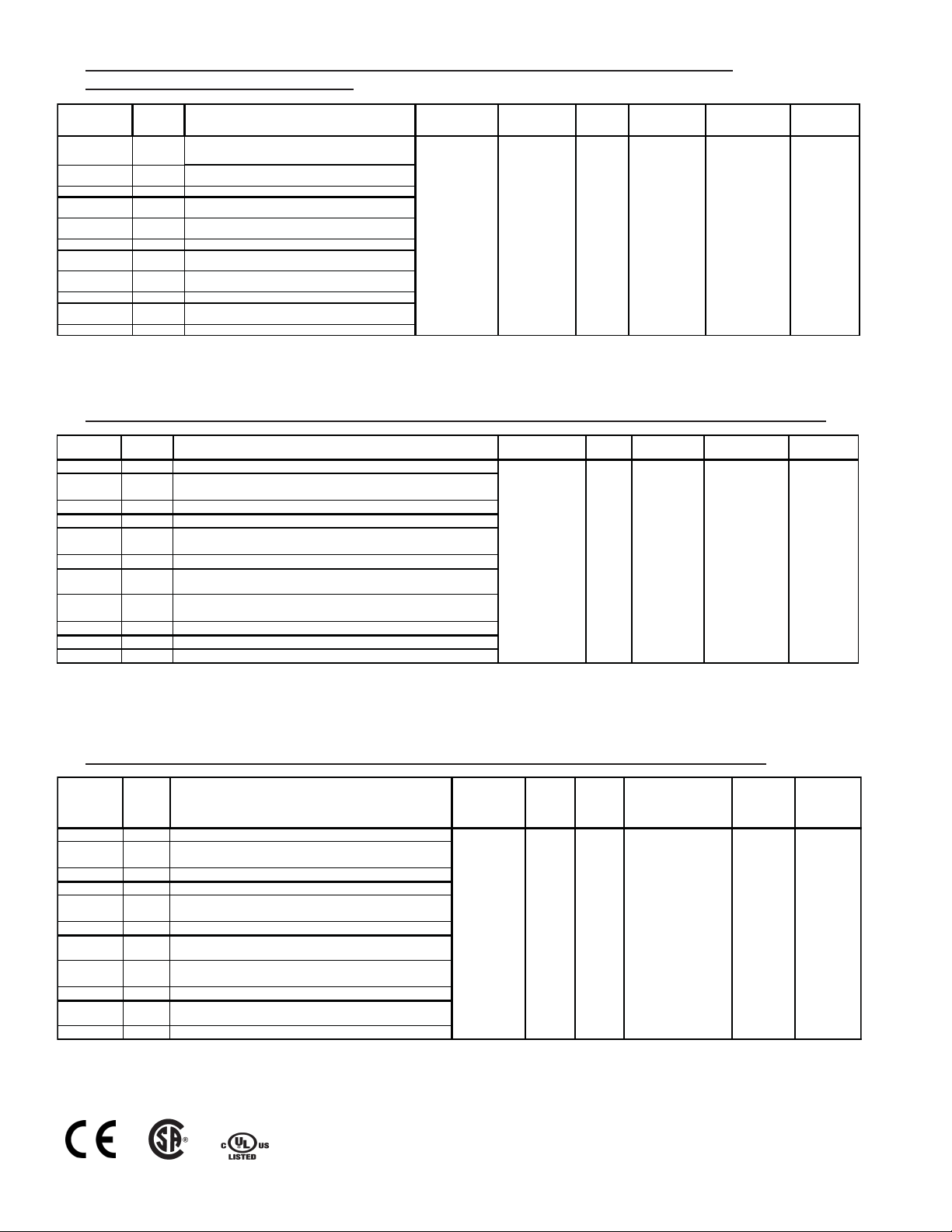
Type Part # Description - (All 50-60 cycles) Temp. Range** Insulation Chamber Size Capacity
t y q v
300/120 1200200
300/120 + 1200201
300ST/120 1200202 Stacking version of above.
300/120-240 1200150 120-240V AC* @ 1000 watts w/ 10' grounded HD cord NO PLUG.
300/120-240 + 1200151
300ST/120-240 1200152 Stacking version of above
300/240-480 1200100 240-480V AC* @ 1000 watts w/ 10' grounded HD cord NO PLUG.
300/ 240-480 + 1200101
300ST/240-480 1200102 Stacking version of above.
300/240 1205400 240-V AC* @ 1000 watts- for use in Canada- NO PLUG.
300ST/240 1205401 Stacking version of above.
*Operation on Direct Current will damage oven and void warranty
**Average Stabilized Temperature @ 70°F Ambient Temperature
120V AC* @ 1000 watts w/10' grounded HD cord.
120V AC* @ 1000 watts w/ 10' grounded HD cord AND installed door
mounted dial thermometer.
120-240V AC* @ 1000 watts w/ 10' grounded HD cord NO PLUG.
Includes installed door mounted dial thermometer.
240-480V AC* @ 1000 watts w/ 10' grounded HD cord NO PLUG.
Includes installed door mounted dial thermometer.
t y q v
t y q v
t q v
t y q v
t q v
t q v
t y q v
t Product is UL listed
v Product is cUL listed
y Product is CSA listed
q Product is CE listed
100° to 550°F (38°
to 288°C) +/- 25°F
(14°C) Adjustable
thermostat control
with indicator light.
glass fiber
2" (5cm)
batt
18" dia. x 19"
deep (46cm x
48cm)
350 lb. (159kg)
of 18" (45.7cm)
electrodes also
accepts 10"
(35.4cm),
12"(30.5cm),
&14"(36cm)
Net Weight &
Dimensions
90 lbs. (41kg) 29
1/2" x 22 1/2" x
22 1/2"
(75x57x57cm)
®
Ship Weight &
Dimensions
115 lbs. (52kg)
26" x 33" x 27"
(66 x 84 x
69cm)
Accessory Note
Model ST - Stacking provision for Type 300 Ovens is available with original
order. Stacking permits two Type 300 ovens to occupy the same floor space
as one. Stacking lugs (factory installed only) on lower oven bolt to feet of
any Type 300 oven, whether in the field or newly ordered.
Accessory Note
If necessary, a Door Mounted Thermometer Kit can be easily installed in the
field (Order Part # 1250300). Factory installation available with original order
(See Part Chart above). This thermometer indicates internal temperature
range of 100° to 700°F. The thermometer accuracy specification is +/- 10°F.
Product accuracy testing is conducted using standards traceable to the
N.I.S.T., USA.
Rev 01/11
N5458100A-1
Page 2
I. INSTRUCCIONES DE OPERACIÓN PARA HORNOS PORTÁTILES TIPO SERIE 300 PARA
q
y
,
ja,
ja,
,
ja,
ja,
j
,
p
-
@
p
ESTABILIZACIÓN DE ELECTRODOS
Tipo Pieza # Descripción - (Todos 50-60 ciclos) Gama de temp.** Aislamiento
120V CA* @ 1000 watts c/ cordón uso rudo, con tierra,
t y q v
300/120 1200200
300/120 + 1200201
300ST/120 1200202
300/120-240 1200150
300/120-240 + 1200151
300ST/120-240 1200152 El anterior
300/240-480 1200100
300/ 240-480 + 1200101
300ST/240-480 1200102 El anterior, en la versión para apilarse
300/240 1205400
300ST/240 1205401 El anterior, en la versión para apilarse
*La operación en corriente directa causará daños al horno y anulará la garantía
**Temperatura estabilizada promedio @ Temperatura ambiente, 21 °C (70 °F)
3 m
120V CA* @ 1000 watts c/ cordón uso rudo, con tierra,
3 m
con termometro
El anterior
en la versión para apilarse
120-240V CA* @ 1000 watts c/ cordón uso rudo, sin
clavi
3 m
120-240V CA* @ 1000 watts c/ cordón uso rudo, sin
3 m y con termometro
clavi
en la versión para apilarse
240-480V CA* @ 1000 watts c/ cordón uso rudo, sin
clavi
3 m
240-480V CA* @ 1000 watts c/ cordón uso rudo, sin
3 m y con termometro
clavi
240-V CA* @ 1000 watts- para usarse en Canada - sin
t y q v
a
clavi
t q v
t y q v
t q v
t y q v
t q v
t y q v
38 a 288 °C (100 a
550 °F) +/- 14 °C
Control con
termostato
ajustable, con luz
piloto.
Bloque de fibra de
vidrio de 5 cm
Tamaño de
cámara
46 cm diam.
x 48 cm
(18" diam. x
19" fondo)
electrodos de
45.7cm. También
acepta de 25.4cm
, 30.5cm y 36cm
t Producto es UL
v Producto es cUL
y Producto es CSA
q Producto es CE
Capacidad
159 kg de
Peso neto y
dimensiones
41 kg 75 x 57 x
57 cm
Peso y
dimensiones
de embar
52Kg 66 x 84 x
69 cm
I. DIRECTIVES D’UTILISATION POUR LES FOURS DE STABILISATION D’ÉLECTRODES, DE SÉRIE 300
Type N° de pièce Description - (Tous de 50-60 cycles) Gamme de temp.** Isolation
t y q v
t y q v
38 °C à 288 °C +/-
14°C (100° à 550 °F +/-
25 °F) Commande de
thermostat réglable
t q v
avec lampe témoin
300/120 1200200
300/120 + 1200201
300ST/120 1200202 Version empilable du modèle susmentionné
C.A.* @ 1000 watts avec cordon à la terre robuste de 3 m
120 V
121 V, C.A.* @ 1000 watts avec cordon à la terre robuste de 3 m et avec termometre
t y q v
t y q v
300/120-240 1200150 120-240 V, C.A.* @ 1000 watts avec cordon à la terre robuste de 3 m - sans fiche
300/120-240 + 1200151
300ST/120-240 1200152 Version em
120-240 V, C.A.* @ 1000 watts avec cordon à la terre robuste de 3 m - sans fiche et avec
termometre
ilable du modèle susmentionné
300/240-480 1200100 240-480 V, C.A.* @ 1000 watts avec cordon à la terre robuste de 3 m - sans fiche
300/240-480 + 1200101
300ST/240-480 1200102 Version empilable du modèle susmentionné
240-480 V, C.A.* @ 1000 watts avec cordon à la terre robuste de 3 m - sans fiche et avec
termometre
t q v
t q v
300/240 1205400 240-V, C.A.* @ 1000 watts- pour le Canada- sans fiche
300ST/240 1205401 Version empilable du modèle susmentionné
t y q v
Panneau
isolant semi
rigide en
fibre de
verre de 5
cm (2 po)
Dim. de la
159 kg d'électrodes de
Diamètre de 46 cm
sur 48 cm de prof.
(18 po sur 19 po)
électrodes de 25,4cm
Contenance Poids net et dim.
45,7cm (18 po), peut
aussi recevoir des
(10 po), 30,5 cm (12
41 Kg 75 cm sur
57 cm sur 57 cm
(29 po 1/2 sur 22
po 1/2 sur 22 po
po) et 36 cm (14 po)
ue
1/2)
*Tout fonctionnement en courant continu endommagera le four et annulera la garantie du même coup
** Température stabilisée moyenne Température ambiante de 21 °C (70 °F)
t Produit est homologué UL
v Produit est homologué cUL
y Produit est homologué CSA
q Produit est homologué CE
I. BEDIENUNGSANLEITUNG FÜR ELEKTRODENSTABILISIERUNGSÖFEN DER SERIE TYP 300
Typ Teile-Nr. Beschreibung - (Alle 50-60 Hz.) Temp.-Bereich** Isolierung
300/120 1200200
120V AC*
1000 Watt m. geerdetem 3m HD-Kabel
t y q v
120V AC* @ 1000 Watt m. geerdetem 3m HD-Kabel mit
300/120 + 1200201
thermometersatz
300ST/120 1200202 Stapelversion des obigen Modells
300/120-240 1200150 120-240V AC* @ 1000 Watt m. geerd. 3m HD-Kabel - kein Stecker
300/120-240 + 1200151
300ST/120-240 1200152 Sta
300/240-480 1200100
300/240-480 + 1200101
120-240V AC* @ 1000 Watt m. geerd. 3m HD-Kabel - kein Stecker
oder mit thermometersatz
elversion des obigen Modells
240-480V AC* @ 1000 Watt m. geerd. 3m HD-Kabel - kein Stecker
t q v
240-480V AC* @ 1000 Watt m. geerd. 3m HD-Kabel - kein Stecker
oder mit thermometersatz
300ST/240-480 1200102 Stapelversion des obigen Modells
300/240 1205400
240-V AC* @ 1000 Watt- zur Verwendung in Kanada- kein Stecker
t y q v
300ST/240 1205401 Stapelversion des obigen Modells
*Bei Betrieb mit Gleichstrom entstehen Schäden am Ofen und die Garantie wird ungültig.
**Durchschnittliche stabilisierte Temperatur @ 21,11°C (70°F) Umgebungstemperatur
t y q v
t y q v
38° bis 288°C
(100° bis 550°F)
+/-14°C
Regulierbarer
Thermostat-regler
mit Anzeigelampe
t q v
t q v
t y q v
Glasfaser-
Kammer-
Größe
46cm
Durchm. x
5cm
48cm tief
watte
(18"
Durchm. x
19")
t Produkt ist UL gelistet
v Produkt ist cUL gelistet
y Produkt ist CSA gelistet
q Produkt ist CE gelistet
Fassungsvermögen
159kg 45,7cm 18"
Elektroden, fasst auch
25,4cm, 30,5cm 36cm
Nettogewicht
&
Dimensionen
41kg 75 x 57 x
57cm
Transportgew.
& Dimensionen
52kg 66 x 84 x
69cm
N5458100A-2
Page 3

II. OVEN TYPE DESCRIPTION
Wiring
Check type and voltage on nameplate.
1. T ype 300, Models 16C & 16STC (120 volts AC only) single
phase.
2. Type 300, Models 15D & 15STD (240/480 volts AC only)
single phase.
*Note: 240/480 volt models are wired at the factory for 240
volts. For 480 volt use, change heating element jumper connections. Provide a plug cap of the corresponding voltage
rating for connection to the power supply.
Grounding
1. The 120 volt ovens have a three blade plug cap with
grounding prong (NEMA 5-15P) attached to a 10 foot power
supply cord. When used with a grounded receptacle, these
ovens meet all local electrical code requirements and are
U.L. Listed.
2. The 240/480 volt ovens have a 10 foot power supply cord.
When used with a grounding plug cap and a grounded
receptacle, these ovens meet all local code requirements.
Electrode Placement
Your DryRod® oven has removable divided shelves to allow
storage of more than one group of electrodes. A void treating
EXX10 or EXX1 1 types at the same time with EXX15, EXX16
and EXX18 electrodes as their holding temperatures vary
widely. Spread the electrodes evenly, allowing space over
each shelf for air circulation required to remove excess moisture. 5" is the maximum suggested layer depth on any shelf.
Guide to Storage
In the absence of detailed storage information from your electrode manufacturer, the "Revised Guide T o Electrode Storage"
(available from Phoenix International, Inc.) may be used as an
indication of approximate temperatures. For Specific information involving critical operations be sure to contact your electrode manufacturer for complete information.
Venting
For normal holding operation set easily adjusted vent on the
door about ¼ open.
Temperature Setting
Temperature range is 100°F (38°C) to 550°F (288°C). The
Thermostat Dial (at rear of oven) is calibrated from 100° to
550°F. Required oven temperature setting is obtained by
rotation of dial to line up desired temperature with indicator
light in the thermostat housing.
The indicator light operates only when voltage is applied to
the heating elements. Momentary rotation past desired temperature setting may be necessary to activate the indicator
light in order to locate it for indexing purposes.
Thermostat is accurate to ± 25°F (14°C) at the sensing bulb,
however, temperature may vary slightly at different areas in
the oven chamber since this is a convection type oven. For
more uniform and accurate temperature control, a re-circulating power blower type of oven is required. (We suggest
Phoenix Type 400BT High Temperature Oven).
Warning
Excess Heat: At the maximum setting, the actual temperature in portions of the oven near the heating elements may
reach approximately 660°F (349°C). Temperatures over
550°F (288°C) are not recommended. They may cause
oven damage and/or unacceptably high exterior surface
temperatures.
Repair - Spare Parts
Enclosed with these instructions are wiring diagrams and a
repair parts list for your oven. For critical welding operations
requiring continuous holding we would suggest carrying all
of the parts listed in the “Suggested Spare Parts Section” of
these instructions.
N5458100A-3
Page 4

II. DESCRIPCIÓN DEL TIPO DE HORNO
Alambrado
En la placa de identificación verifique el tipo y el voltaje.
1. Tipo 300, modelos 16C y 16STC (solamente 120 voltios CA) monofásicos.
2. Tipo 300, modelos 15D y 15STD (solamente 240/480 voltios CA) monofásicos.
*Nota: Los modelos de 240/480 voltios se alambran en la fábrica para 240 voltios. Para
usarse en 480 voltios, cambie las conexiones del puente del elemento calefactor. Para la
conexión a la fuente de energía proporcione una clavija de conexión de la clasificación de
voltaje correspondiente.
Conexión a tierra
1. Los hornos para 120 voltios tienen una clavija de conexión de tres hojas con terminal de
tierra (NEMA 5-15P) conectada a un cordón de alimentación de energía de 3 metros (10
pies). Cuando se usan con un receptáculo conectado a tierra, estos hornos cumplen con
todos los requisitos locales del código eléctrico y están incluidos en U.L.
2. Los hornos de 240/480 voltios tienen un cordón de alimentación de energía de 3 metros
(10 pies). Cuando se usan con una clavija de conexión conectada a tierra y un receptáculo
conectado a tierra, estos hornos cumplen con todos los requisitos locales del código.
Colocación de los electrodos
Su horno DryRod® tiene entrepaños divisorios desmontables para permitir el almacenaje
de más de un grupo de electrodos. Evite dar tratamiento simultáneo a los electrodos
EXX10 o EXX11 con los EXX15,EXX16 y EXX18 ya que la temperatura a la que se deben
mantener varía ampliamente. Esparza uniformemente los electrodos dejando espacio
sobre cada entrepaño para la circulación de aire necesaria para remover el exceso de
humedad. El máximo espesor que se sugiere para cada capa de cualquier entrepaño es
de 12.7 cm (5”).
Guía para almacenaje
A falta de información detallada sobre el almacenaje por parte del fabricante de electrodos,
II. DESCRIPTION DU TYPE DE FOUR
Câblage
Consulter la plaque signalétique pour connaître le type de câblage et la tension.
1. Type 300, modèles 16C et 16STC (120 volts, c.a. seulement) monophasé.
2. Type 300, modèles 15D et 15STD (240/480 volts, c.a. seulement) monophasé.
*Nota :Les modèles de 240/480 volts sont câblés en usine pour une tension de 240
volts. Pour utiliser une tension de 480 volts, modifier les connexions de cavalier des
éléments chauffants. Pour une connexion au secteur, fournir une cache-fiche dont
la capacité de tension correspond au cordon.
Mise à la terre
1. Les fours de 120 volts comportent un cordon d’alimentation de 3 m (10 pi) doté d’une
cache-fiche à 3 broches avec broche de masse (NEMA 5-15P). Ces fours satisfont à toutes
les exigences reliées au code d’électricité local s’ils sont branchés à une prise de masse.
De plus, ils sont répertoriés par l’U.L.
2. Les fours de 240/480 volts comportent un cordon d’alimentation de 3 m (10 pi). Ces
fours satisfont à toutes les exigences reliées au code d’électricité local s’ils sont utilisés
avec une cache- fiche munie d’un fil de terre et une prise de masse.
Mise en place des électrodes
Votre four DryRod® comporte des plaques séparées amovibles, ce qui permet l’entreposage
de plus d’un groupe d’électrodes. Éviter de traiter les électrodes de types EXX10 ou
EXX11 en même temps que celles de types EXX15, EXX16 et EXX18, car leur température
de maintien varie largement. Étendre les électrodes uniformément et laisser de l’espace
au-dessus de chaque plaque pour permettre la circulation d’air qui est nécessaire pour
enlever tout excès d’humidité. La profondeur de couche maximale suggérée pour chaque
plaque est de 13 cm (5 po).
Guide d’entreposage
Si votre fabricant d’électrodes ne vous a pas fourni d’information détaillée sur l’entreposage,
le « Guide révisé sur l’entreposage des électrodes » (offert auprès de Phoenix International,
se puede utilizar la “Guía revisada sobre almacenaje de electrodos” (disponible en Phoenix
International, Inc.) como una indicación aproximada de las temperaturas. Respecto a
información específica que involucre operaciones críticas asegúrese de ponerse en contacto con el fabricante de los electrodos para obtener información completa.
Ventilación
Para la operación normal de mantenimiento de temperatura, coloque la ventila fácilmente
ajustable de la puerta en la posición de ¼ abierta
Ajuste de la temperatura
La gama de temperatura es de 38 °C (100 °F) a 288 °C (550 °F).
La carátula del termostato (atrás del horno) está calibrada de 38 a 288 °C (100 a 550 °F).
El ajuste de la temperatura deseada del horno se obtiene girando la carátula hasta alinear
la temperatura deseada con la luz piloto en la cubierta del termostato.
La luz piloto opera solamente cuando se le aplica voltaje a los elementos calefactores. Es
posible que sea necesario un giro momentáneamente hasta pasar la marca de la temperatura deseada para activar la luz piloto, para localizarla con fines de graduación.
El termostato tiene una precisión de ± 14 °C (25 °F) en el bulbo detector, sin embargo, la
temperatura puede variar ligeramente en diferentes áreas de la cámara del horno debido
a que es un horno del tipo por convección. Para un control más uniforme y exacto de la
temperatura, se requiere un horno de tipo soplador de recirculación motorizado.
(Sugerimos el Horno de Alta Temperatura Phoenix Tipo 400 BT).
Advertencia
Calor excesivo: Al ajuste máximo, es posible que la temperatura real en algunas partes
del horno, cerca de los elementos calefactores pueda alcanzar aproximadamente 349 °C
(660 °F). No se recomiendan temperaturas superiores a 288 °C (550 °F). Pueden causar
daño al horno y/o temperaturas altas inaceptables en la superficie exterior.
Inc. peut être utilisé à titre indicatif pour connaître les températures approximatives. Pour
obtenir une information précise sur des opérations critiques, assurez-vous de communiquer avec votre fabricant d’électrodes pour avoir toute l’information nécessaire.
Mise à l’air libre
Dans le cas d’une opération de conservation normale, ouvrir de l’évent à réglage convivial
situé sur la porte.
Réglage de température
La gamme de température varie entre 38 °C (100 °F) et 288 °C (550 °F). Le cadran du
thermostat (à l’arrière du four) est étalonné de 38 °C (100 °F) à 288 °C (550 °F). Pour
obtenir le réglage de température du four recherché, il suffit de tourner le cadran de façon
à aligner la température voulue avec la lampe témoin du boîtier du thermostat.
La lampe témoin fonctionne uniquement lorsque la tension est appliquée aux éléments
chauffants. Il peut être nécessaire de régler momentanément le cadran au delà du réglage
de température recherché afin d’activer la lampe témoin en vue de la repérer à des fins
d’indexage.
Le thermostat affiche une exactitude de ± 14 °C (25 °F)au niveau du bulbe thermostatique.
Cependant, la température peut varier légèrement selon les différents points de la chambre
de cuisson, car il s’agit d’un four à convection. Un four doté d’un ventilateur de recirculation
motorisé est nécessaire pour obtenir une régulation de température plus uniforme et précise. (Nous vous suggérons le four haute température de type 400BT de Phoenix).
Avertissement
Excès de chaleur : Au réglage maximal, la température réelle des parties du four situées
près des éléments chauffants peut atteindre environ 349 °C (660 °F). Des températures
supérieures à 288 °C (550 °F) ne sont pas recommandées. Des températures élevées
peuvent endommager le four ou augmenter les températures de la surface extérieure à un
niveau élevé inacceptable.
II. BESCHREIBUNG DES OFENTYPS
Leitungsführung
Typ und Spannung am Namenschild überprüfen.
1. Typ 300, Modelle 16C & 16STC (nur 120 VAC) einphasig.
2. Typ 300, Modelle 15D & 15STD (nur 240/480 VAC) einphasig.
*Zu beachten 240/480 Volt Modelle wurden bei der Herstellung auf 240 Volt eingerichet.
Für den Einsatz bei 480 Volt müssen die Steckverbinder an den Heizelementen ausgeschauscht werden. Verwenden Sie zum Anschließen des Ofen an die Stromquelle einen
Stecker für die entsprechende Spannung.
Erdung
1. Die 120 Volt Öfen haben einen drei-polige Stecker mit Erdungsklemme (NEMA 5-15P)
an einem 304,80 cm (10 foot) langen Kabel. Bei Verwendung mit einer geerdeten
Steckdose erfüllen diese Öfen sämtliche örtlichen Elektrikvorschriften und befinden sich auf
der U.L.-Liste..
2. Die 240/480 Volt Öfen haben ein 304,80 cm (10 foot) langes Netzkabel. Bei V erwendung
mit einem Erdungsstecker und einer geerdeten Steckdose erfüllen diese Öfen sämtliche
örtlichen Vorschriften.
Elektrodenplatzierung
Ihr DryRod-Ofen hat herausnehmbare unterteilte Regale auf denem mehr als eine
Elektrodengruppe gelagert werden kann. Vermeiden Sie es, die T ypen EXX10 oder EXX11
gleichzeitig wir Elektroden der Typen EXX15, EXX16 und EXX18 zu behandeln, da sich
ihre Aufbewahrungstemperaturen stark unterscheiden. V erteilen Sie die Elektroden gleichmäßig, so dass über jedem Regal genügend Platz zur Luftzirkulation für die Beseitung von
übermäßiger Feuchtigkeit voprhanden ist. Die Schichttiefe pro Regal sollte 12,7 cm (5 Zoll)
nicht übersteigen.
Lagerungsrichtlinien
Sollten Sie keine detaillierten Lagerungshinweise vom ihrem Elektrodenhersteller bekom-
men haben, können Sie den „Revised Guide To Electrode Storage“ (Überarbeitete
Richtlinien zu Elektrodenlagerung) (erhältlich von Phoenix International, Inc.) zum
Nachschlagen von Lagerungstemperaturen verwenden. Wenden Sie sich unbedingt an
Ihren Elektrodenhersteller für spezifische Informationen hinsichtlich besonderer
Anwendungen.
Belüftung
Stellen Sie die leicht zu regulierende Belüftung an der Tür für den normalen Betriet auf etwa
¼ offen.
Temperatureinstellung
Der Temperaturbereich ist 38°C (100°F) bis 288°C (500°F). Der Thermostatregler (an der
Rückseite des Ofens) ist von 38°C (100°F) bis 287°C (550°F) kalibriert.Zum Erreichen der
gewünschten Temperatureinstellung wird der Regler gedreht, bis die gewünschte
Temperatur mit der Anzeigelampe am Thermostatgehäuse übereinstimmt.
Die Anzeigelampe leuchtet nur auf, wenn den Heizelementen Spannung zugeführt wird.
Der Regler muss zur Aktivierung der Anzeigelampe eventuell kurz über die gewünschte
Temperatureinstellung hinaus gedreht werden.
Der Thermostat hat am Sensor eine Genauigkeit von ± 14°C (25°F), jedoch kann die
Temperatur in verschiedenen Bereichen im Ofen leicht variieren, da der Ofen ein
Konvektionsofen ist. Für eine gleichmäßigere und genauere Temperaturkontrolle wird ein
Umluftofen mit Gebläse benötigt. (Wir empfehlen den Phoenix Typ 400BT HochtemperaturOfen.
Warnung
Übermäßige Hitze: Bei der Maximaleinstellung kann die tatsächliche Temperatur in manchen Ofenbereichen in der Nähe der Heizelemente ca. 349°C (660°F) erreichen.
T emperaturen über 288°C (550°F) sind nicht ratsam. Dies kann zu Schäden am Ofen und/
oder unzulässig hohen Temperaturen an der Außenseite führen.
N5458100A-4
Page 5

**CAUTION**
All wiring should be done by licensed electricians in accordance with local codes.
Improper installation or use may result in serious injury. Always remove oven from
power source before troubleshooting or repairing.
III. TROUBLESHOOTING - TYPE 300 OVENS
OVEN FAILS TO OPERATE - NO HEAT
1. If oven indicator light will not illuminate, check power supply .
2. Check plug at outer end of power cord and run continuity
check on complete power cord. If defective, replace cord
assembly.
3. Check indicator light for continuity (see Repair Parts drawing for access details). If defective, replace indicator light.
4. Check thermostat at rear of oven. If indicator light illuminates, power is being supplied through thermostat to dual
heating elements. Turn knob from low to high setting and
return. Definite "snap" should be heard at low temperature
end and indicator light should turn off and on with each
"snap" cycle. If "snap" is not heard and indicator light fails to
operate, replace entire thermostat. (See Repair Parts Sheet
and "Suggested Spare Parts").
5. If thermostat operates satisfactorily, check continuity of
dual hairpin style heating elements at bottom center of oven.
(see Repair Parts drawing for access details.) Failure of one
element will prevent oven operation on 480 volts. If operating on 120 or 240 volts failure of one element will cause very
slow heating.
Remove oven from power source. Replace BOTH elements. Pairing of one new element with an old element may
cause rapid failure of old element.
OVEN OPERATES - OVERHEATS
Check thermostat operation as in number 3 (Oven Fails To
Operate - No Heat) and number 2 (Oven Operates Temperatures Setting Off).
OVEN OPERATES - TEMPERATURE SETTING
“OFF”
1. Check thermostat operation as in number 3 (Oven Fails
To Operate - No Heat) and number 2 (Oven Operates Temperature Setting Off)
2. If thermostat operates satisfactorily, recalibrate per thermostat calibration adjusting sheet.
DOOR WILL NOT CLOSE PROPERLY
1. Use screwdriver to adjust door latch (No.2 on Repair Parts
drawing - front view).
2. If latch is broken, replace. Order spare Part No. 1252200,
door latch and strike.
N5458100A-5
Page 6

Todo el alambrado lo debe hacer un electricista autorizado de acuerdo con los códigos locales. La instalación o uso inadecuado puede
**PRECAUCIÓN**
resultar en lesiones graves. Siempre desconecte el horno de la fuente de energía antes de investigar y resolver problemas o reparar.
III. RESOLUCIÓN DE PROBLEMAS - HORNOS TIPO 300
EL HORNO FALLA EN SU OPERACIÓN - NO CALIENTA
1. Si la luz piloto del horno no se ilumina, verifique la alimentación de energía.
2. Revise la clavija y el extremo de salida del cordón de alimentación de energía
y haga verificaciones de continuidad en todo el cordón de alimentación. Si está
defectuoso, reemplace todo el conjunto del cordón.
3. Revise la continuidad de la luz piloto (Consulte el dibujo de las piezas de
repuesto para obtener los detalles de acceso). Si está defectuosa la luz piloto,
reemplácela.
4. Revise el termostato atrás del horno. Si la luz piloto se ilumina, se está alimentando energía a los elementos calefactores duales a través del termostato.
Gire la perilla del ajuste bajo al alto y regrese. Se debe escuchar un “chasquido”
definido en el extremo de baja temperatura y la luz piloto se debe apagar y
encender con cada ciclo de “chasquido”. Si no se escucha el “chasquido” y la luz
piloto falla en operar, reemplace el termostato completo. (Consulte la hoja de
piezas de repuesto y “Piezas de repuesto sugeridas”).
5. Si el termostato opera satisfactoriamente, revise la continuidad de los elementos calefactores duales tipo espiga capilar en el fondo del centro del horno.
(Consulte el dibujo de piezas de repuesto para obtener los detalles de acceso).
La falla de un elemento no permitirá que el horno opere a 480 voltios. Si están
operando en 120 o 240 voltios la falla de un elemento causará calentamiento muy
lento. Desconecte el horno de la fuente de energía. Reemplace AMBOS elementos. Juntar un elemento nuevo con un elemento viejo puede causar la falla rápida
del elemento viejo.
EL HORNO OPERA - SE SOBRECALIENTA
Revise la operación del termostato como en el número 3 (El horno falla en su
operación - No calienta) y el número 2 (El horno opera - Temperaturas desajustadas).
EL HORNO OPERA - TEMPERATURAS “DESAJUSTADAS”
1. Revise la operación del termostato como en el número 3 (El horno falla en su
operación - No calienta) y el número 2 (El horno opera - Temperaturas desajustadas).
2. Si el termostato opera satisfactoriamente, volver a calibrarlo según la hoja de
instrucciones para ajustar la calibración del termostato.
LA PUERTA NO CIERRA ADECUADAMENTE
1. Utilice un desatornillador para ajustar el pasador de la puerta (No. 2 de dibujo
de partes de repuesto - vista frontal).
2. Si el pasador está roto, reemplácelo. Pida la pieza de repuesto No. 1252200,
pasador y hembra.
**ATTENTION**
Le câblage doit être effectué par des électriciens agréés en conformité avec les codes régionaux. Toute installation ou utilisation inadéquate
peut entraîner des blessures graves. Toujours débrancher le four avant d'effectuer un dépannage ou une réparation.
III. DÉPANNAGE — FOURS DE TYPE 300
ÉCHEC DE FONCTIONNEMENT DU FOUR- AUCUNE CHALEUR
1. Si la lampe témoin du four ne s’allume pas, vérifier l’alimentation.
2. Vérifier la fiche du cordon et effectuer un contrôle de continuité sur tout le cordon. Si le cordon est défectueux, le remplacer.
3. Vérifier la continuité de la lampe témoin (consulter le dessin des pièces de
réparation pour obtenir l’information détaillée sur l’accès). Si la lampe témoin est
défectueuse, la remplacer.
4. Vérifier le thermostat à l’arrière du four. Si la lampe témoin s’allume, cela signifie que les deux éléments chauffants sont alimentés en courant par l’intermédiaire
du thermostat. Tourner le bouton de la position basse à élevée, puis retourner à
la position initiale. Un « claquement » clair doit être entendu à la position de
température basse, et la lampe témoin doit s’éteindre puis s’allumer à chaque
cycle de « claquement ». Si aucun « claquement » ne se fait entendre et que la
lampe témoin ne fonctionne pas, remplacer tout le thermostat. (Consulter la Fiche
des pièces de réparation et la section « Pièces de rechange suggérées »).
5. Si le thermostat fonctionne de façon satisfaisante, vérifier la continuité des deux
éléments chauffants en forme d’épingle à cheveux situés au centre inférieur du
four. (consulter le dessin des pièces de réparation pour obtenir de l’information
détaillée sur l’accès). La défaillance d’un élément empêchera le fonctionnement
du four à une tension de 480 volts. Dans le cas d’un four fonctionnant selon une
tension de 120 ou 240 volts, la défaillance d’un élément provoque un ralentisse-
ment important du chauffage. Débrancher le four. Remplacer les DEUX éléments.
L’association d’un élément neuf avec un élément usagé risque de provoquer
rapidement une défaillance de l’élément usagé.
FONCTIONNEMENT DU FOUR- SURCHAUFFE
Vérifier le fonctionnement du thermostat comme il est indiqué au numéro 3 (Échec
de fonctionnement du four — Aucune chaleur) et au numéro 2 (Fonctionnement
du four — Activation des températures).
FONCTIONNEMENT DU FOUR — ACTIVATION DE LA
TEMPÉRATURE
1. Vérifier le fonctionnement du thermostat comme il est indiqué au numéro 3
(Échec de fonctionnement du four — Aucune chaleur) et au numéro 2
(Fonctionnement du four — Activation de la température)
2. Si le thermostat fonctionne de façon satisfaisante, réétalonner selon la fiche de
réglage pour l’étalonnage du thermostat.
LA PORTE NE SE FERME PAS ADÉQUATEMENT
1. Utiliser un tournevis pour ajuster le loquet de la porte ( N° 2 du dessin Pièces
de rechange — vue de face).
2. Si le loquet est brisé, le remplacer. Commander la pièce de rechange n°
1252200, loquet de porte et gâche.
Die Verlegung der Kabel sollte nur von Elektrikern in Übereinstimmung mit den örtlichen Vorschriften durchgeführt werden. Falsche
**VORSICHT**
Installation oder Verwendung kann zu schweren Verletzungen führen. Vor der Fehlersuche oder Reparatur Ofen immer von der
Stromquelle abtrennen.
III. FEHLERBEHEBUNG — TYP 300 ÖFEN
OFEN FUNKTIONIERT NICHT — KEINE WÄRME
1. Falls die Ofen-Anzeigelampe nicht aufleuchtet, Stromquelle überprüfen.
2. Stecker am äußeren Ende des Stromkabels prüfen und Durchgangsprüfung am
ganzen Stromkabel durchführen. Kabel, falls defekt, austauschen.
3. Durchgangsprüfung an der Anzeigelampe durchführen (siehe ReparaturteileZeichnung für Zugriffsdetails). Anzeigelampe, falls defekt, austauschen.
4. Thermostat an der Ofenrückseite überprüfen. Wenn die Anzeigelampe
aufleuchtet, wird den beiden Heizelementen durch den Thermostat Strom
zugeführt. Regler von der niedrigsten zur höchsten Stufe und wieder zurück
drehen. Im unteren Temperaturbereich sollte ein deutliches „Schnapp“ zu hören
sein, und die Anzeigelampe sollte mit jedem „Schnapp“-Zyklus aus- und angehehen. Wenn kein „Schnapp“ zu hören ist und die Anzeigelampe nicht funtioniert
den ganzen Thermostat austauschen. Siehe das Blatt „Reparaturteile“ und den
Abschnitt „Empfohlene Ersatzteile“)
5. Falls der Thermostat ordnungsgemäß funktioniert, Durchgangsprüfung an den
beiden U-förmigen Heizelementen in der Mitte unten im Ofen durchführen (siehe
Reparaturteile-Zeichnung für Zugriffsdetails). Bei Versagen eines Elements kann
der Ofen nicht bei 480 Volt betrieben werden. Bei Betrieb bei 120 oder 240 Volt
hat das Versagen eines Elements sehr langsames Aufheizen zur Folge. Ofen von
der Stromquelle entfernen. BEIDE Elemente austauschen. Wenn ein neues
Element mit einem alten Element kombiniert wird, kann es zu schnellem Versagen
des alten Elements kommen.
OFEN FUNKTIONIERT - ÜBERHITZT
Thermostatbetrieb wie unter Nummer 3 (Ofen funktioniert nicht — keine Wärme)
und Nummer 2 (Ofen funktioniert — Temperatureinstellung stimmt nicht) beschrieben prüfen.
OFEN FUNKTIONIERT — TEMPERATUREINSTELLUNG STIMMT
NICHT
1. Thermostatbetrieb wie unter Nummer 3 (Ofen funktioniert nicht — keine
Wärme) und Nummer 2 (Ofen funktioniert — Temperatureinstellung stimmt nicht)
beschrieben prüfen.
2. Falls der Thermostat ordnungsgemäß funktioniert, Thermostat gemäß dem
Blatt „Kalibrierung einstellen“ neukalibrieren.
TÜR SCHLIESST NICHT RICHTIG
1. Türriegel mit einem Schraubenzieher feststellen (Nr. 2 auf der ReparaturteileZeichnung — Frontansicht).
2. Den Riegel austauschen, falls er kaputt ist. Ersatzteil-Nr. 1252200, Türriegel
und —raste.
N5458100A-6
Page 7

TYPE 300, 120 & 240V WIRING DIAGRAM
Factory Installed
Indicator Light
Heating
Element
Conduit Box
White
Black
Green
Alternate
Connection
Of Indicator
Light
Type K
Thermostat
TYPE 300, 480V WIRING DIAGRAM
N5458100A-7
Page 8

A
C
D
H
I
G
E
B
E
F
A
C
D
H
G
B
F
I
DIAGRAMA DE ALAMBRADO PARA TIPO 300
SCHÉMA DE CÂBLAGE, TYPE 300
TYP 300 SCHALTPLAN
DIAGRAMA DE ALAMBRADO PARA TIPO 300
SCHÉMA DE CÂBLAGE, TYPE 300
TYP 300 SCHA
A.. Luz piloto instalada en fábrica
B. Elemento calefactor
C. Termostato tipo K
D. Alternativa de conexión de la Luz piloto
E. Puente (1) de 2
F. Caja de salida
G. Verde
H. Blanco
I. Negro
A. Lampe témoin installée en usine Voyant
B. Élément chauffant
C. Thermostat de type K
D. Connexion alternative de la lampe témoin
E. Cavalier (1) de 2
F. Boîte de raccordement
G. Vert
H. Blanc
I. Noir
A. Eingebaute Anzeigelampe
B. Heizelement
C. Typ K Thermostat
D. Alternativer Anzeigenlampenanschluss
E. Steckverbinder (1) von 2
F. Klemmenkasten
G. Grün
H. Weiß
I. Schwarz
N5458100A-8
Page 9

IV. TYPE 300 REPAIR PARTS ILLUSTRATION
3
WHEN ORDERING, SPECIFY PART NUMBER,
DESCRIPTION, QUANTITY AND THE
FOLLOWING NAMEPLATE DATA: "TYPE,
MODEL NO. AND VOLTAGE".
Phoenix International, Inc. • 8711 West Port Avenue • Milwaukee, WI 53224 USA
Phone (414) 973-3400 • Fax (414) 973-3275 • www.phx-international.com • info@phx-international.com
N5458100A-9
Page 10

IV. ILUSTRACIÓN DE PIEZAS DE REPUESTO
TIPO 300
IV. ILLUSTRATION DER REPARATURTEILE
TYP 300
IV. ILLUSTRATION DES PIÈCES DE RÉPARATION
Phoenix International, Inc.
8711 West Port Avenue • Milwaukee, WI 53224 USA
Phone (414) 973-3400 • Fax (414) 973-3210
www.phx-international.com • info@phx-international.com
TYPE
300
3
CUANDO SE HAGA UN PEDIDO, ESPECIFIQUE EL NÚMERO DE
PIEZA, DESCRIPCIÓN, CANTIDAD Y LOS SIGUIENTES DATOS DE
LA PLACA DE IDENTIFICACIÓN: “TIPO, NO. DE MODELO Y
VOLTAJE”.
DANS VOTRE COMMANDE, INDIQUER LE NUMÉRO DE PIÈCE, LA
DESCRIPTION, LA QUANTITÉ ET LES DONNÉES SUIVANTES SUR
LA PLAQUE SIGNALÉTIQUE : « TYPE, NO DE MODÈLE ET
TENSION ».
BEI BESTELLUNGEN TEILENUMMER, BESCHREIBUNG, MENGE
UND DIE FOLGENDEN NAMENSSCHILDDATEN ANGEBEN: „TYP,
MODELL-NR. UND SPANNUNG“.
N5458100A-10
Page 11

TYPE 300 REPAIR PARTS ILLUSTRATION (Continued)
6
5
14
A. To Heating Elements
B. Ground Wire
12
A
B
10
15
1
Thermostat probe must be
inserted fully into oven chamber. During replacement of
thermostat housing, con rm
copper thermostat probe does
not contact thermostat supply
leads.
2
Note
Always replace BOTH heating elements if one fails.
(Two are required for each oven.) Replacement elements are sold in sets of (2) each only.
Phoenix International, Inc. • 8711 West Port Avenue • Milwaukee, WI 53224 USA
Phone (414) 973-3400 • Fax (414) 973-3275 • www.phx-international.com • info@phx-international.com
N5458100A-11
Page 12

Type 300
6
A
B
A. A los elementos calefactores
A. Aux éléments chauffants
A. Zu den Heizelementen
B. Alambre de tierra
B. Fil de terre
B. Erdungsdraht
Nota
Siempre reemplace AMBOS elementos calefactores si
uno de ellos falla. (Se requieren dos para cada horno)
Los elementos de reemplazo se venden en juegos de (2)
solamente.
Nota
Toujours remplacer les DEUX éléments chauffants en
cas de défaillance d’un élément. (Chaque four requiert
deux éléments.) Les éléments de rechange ne sont vendus qu’en jeu de (2) éléments seulement.
Zu beachten
Falls ein Heizelement versagt, immer BEIDE austauschen. (Jeder Ofen braucht zwei Heizelemente.)
Ersatzelemente werden nur als Zweiersätze verkauft.
Phoenix International, Inc. • 8711 West Port Avenue • Milwaukee, WI 53224 USA
Phone (414) 973-3400 • Fax (414) 973-3275 • www.phx-international.com • info@phx-international.com
N5458100A-12
Page 13

V. SUGGESTED SPARE PARTS TYPE 300 OVENS
Following quantities for each oven:*
• One (1) kit of (2) heating elements No. 1250500 (120 volt
models)
• One (1) kit of (2) heating elements No. 1250600 (240/480
volt models)
• One (1) thermostat, kit No. 1251100 (120 volt models)
• One (1) thermostat, kit No. 1251200 (240/480 volt mod-
*For quantities of ovens exceeding 10, we suggest providing approximately 20% more of the above quantities of spares
as sufficient for day to day operation.
For overseas operation we suggest a minimum of 30% more for spares.
Phoenix International, Inc. warrants its products against defects
in material and workmanship. The company will, at its discretion, repair or replace any properly installed Phoenix
International manufactured product which fails under normal
operating conditions within one year from date of receipt.
Contact the factory for return authorization before returning the
product to Phoenix International freight prepaid. If our inspection confirms that the product is defective under terms of this
warranty, it will be repaired/ replaced and returned freight prepaid.
els)
• One (1) door latch and strike No. 1252200
• One (1) insulation block No. 1252400
• One (1) 10 foot connection cord with cap & strain relief, No.
1257120 (120 volt models).
• One (1) 10 foot connection cord without plug cap, No.
This warranty applies only to Products sold by Phoenix
International, Inc. and specifically excludes installation or deinstallation labor, transportation, or equipment of another
manufacturer used in conjunction with Phoenix International
products. No other warranty, expressed or implied, exists
beyond this warranty declaration.
Phoenix constantly strives to improve its products and therefore reserves the right to change design, materials, and specifications without notice.
Phoenix International, Inc.
8711 West Port Avenue
Milwaukee, WI 53224 USA
Phone (414) 973-3400
Fax (414) 973-3275
www.phx-international.com
info@phx-international.com
N5458100A-13
Page 14

V. PIEZAS DE REPUESTO SUGERIDAS PARA HORNOS TIPO 300
Las siguientes cantidades para cada horno.*
• Un (1) juego de (2) elementos calefactores No. 1250500 (modelos de
120 Voltios)
• Un (1) juego de (2) elementos calefactores No. 1250600 (modelos
de 240/480 Voltios)
• Un (1) termostato, juego No. 1251100 (modelos de 120 voltios)
• Un (1) termostato, juego No. 1251200 (modelos de 240/480 voltios)
*Para cantidades de más de 10 hornos, sugerimos suministrar aproximadamente el 20% más de las cantidades anteriores de refacciones como
suficientes para la operación diaria.
Para operaciones en el extranjero sugerimos un mínimo de 30% más de refacciones.
• Un (1) pasador y hembra para puerta, No. 1252200
• Un (1) bloque de aislamiento, No. 1252400
• Un (1) cordón de conexión de 3 metros (10 pies) con clavija y a
prueba de jalones, No. 1257120 (modelos de 120 voltios).
• Un (1) cordón de conexión de 3 metros (10 pies) sin clavija, No.
1257121 (modelos de 240/480 voltios).
Phoenix International, Inc. garantiza sus productos contra defectos en materiales y mano de obra. A su discreción, la compañía reparará o reemplazará
cualquier producto manufacturado por Phoenix International que haya sido
instalado adecuadamente y que haya fallado bajo condiciones de operación
normales dentro del plazo de un año a partir de la fecha de haberse recibido.
Póngase en contacto con la fábrica para la autorización de una devolución
antes de regresar el producto a Phoenix International con flete pagado por
anticipado. Si nuestra inspección confirma que el producto está defectuoso
bajo los términos de esta garantía, se reparará o reemplazará y se regresará
con flete pagado por anticipado. Esta garantía se aplica solamente a los
productos vendidos por Phoenix International, Inc. y específicamente
excluye la mano de obra de instalación, desmontaje, transportación, o
equipo de otro fabricante utilizado en conjunto con productos de Phoenix
International. No existe ninguna otra garantía, expresa o implícita más allá
de esta declaración de garantía.
Phoenix constantemente se esfuerza por mejorar sus productos y por consiguiente se reserva el derecho de cambiar el diseño, materiales y especificaciones sin aviso previo.
V. PIÈCES DE RECHANGE SUGGÉRÉES POUR LES FOURS DE TYPE 300
Les quantités suivantes sont données pour chaque four :*
• Un (1) nécessaire de (2) éléments chauffants, n° 1250500 (modèles
de 120 volts)
• Un (1) nécessaire de (2) éléments chauffants, n° 1250600 (modèles
de 240/480 volts)
• Un (1) thermostat, nécessaire n° 1251100 (modèles de 120 volts)
• Un (1) thermostat, nécessaire n° 1251200 (modèles de 240/480
*Pour un nombre de fours supérieur à 10, nous suggérons de fournir un nombre de pièces de rechange supérieur d’environ 20 % au nombre susmentionné pour une exploitation quotidienne.
Pour une exploitation à l’étranger, nous suggérons un nombre de pièces de rechange supérieur d’au moins 30 %.
Phoenix International, Inc. garantit ses produits contre tout défaut de matériau et de main d’œuvre. La compagnie, à sa discrétion, réparera ou remplacera tout produit fabriqué par Phoenix International qui a été installé
correctement et qui présente une défaillance dans des conditions normales
de fonctionnement. La garantie dure un an à partir de la date de la facture.
Communiquer avec l’usine pour obtenir une autorisation de retour avant de
retourner le produit à Phoenix International, le fret étant payé d’avance. Si
notre inspection confirme la défaillance du produit et qu’il est couvert par les
termes de cette garantie, le produit sera réparé ou remplacé, puis retourné,
volts)
• Un loquet de porte et une gâche n° 1252200
• Un (1) bloc isolant, n° 1252400
• Un (1) cordon d’alimentation de 3 m (10 pi) avec cache-fiche et réducteur de tension, n° 1257120 (modèles de 120 volts).
• Un (1) cordon d’alimentation de 3 m (10 pi) sans cache-fiche, n°
1257121 (modèles de 240/480 volts).
le fret étant payé d’avance. Cette garantie s’applique uniquement aux
produits vendus par Phoenix International, Inc. et exclue spécifiquement
l’installation ou la désinstallation, la main d’œuvre, le transport ou l’équipement
d’un autre fabricant utilisé conjointement avec les produits de Phoenix
International. Il n’y a pas d’autre garantie, explicite ou implicite, que la
présente garantie.
Phoenix s’efforce constamment d’améliorer ses produits et se réserve donc
le droit de modifier les modèles, matériaux et spécifications sans pr
V. EMPFOHLENE ERSATZTEILE FÜR ÖFEN VOM TYP 300
Für jeden Ofen gelten die folgenden Mengen:*
• Ein (1) Zweiersatz Heizelemente Nr. 1250500 (120 Volt Modelle)
• Ein (1) Zweiersatz Heizelemente Nr. 1250600 (240 Volt Modelle)
• Ein (1) Thermostat, Satz Nr. 1251100 (120 Volt Modelle)
• Ein (1) Thermostat, Satz Nr. 1251200 (240/480 Volt Modelle)
• Ein (1) Türriegel und eine —Raste, Nr. 1252200
*Bei mehr als 10 Öfen empfehlen wir, dass für den problemlosen täglichen Betrieb etwa 20% mehr der oben angegebenen Mengen zur Verfügung
stehen.
Für Einsätze in Übersee empfehlen wir mindestens 30% mehr Ersatzteile.
Phoenix International, Inc. garantiert seine Produkte gegen Material und
Herstellungsfehler. $$$ Die Firma wird alle richtig installierten Produkte von
Phoenix International, die unter normalen Betriebsbedingungen innerhalb
eines Jahres nach dem Datum des Kaufbelegs, versagen nach eigenem
Ermessen reparieren oder ersetzen. Kontaktieren Sie die Firma, bevor Sie
das Produkt auf eigene Kosten an Phoenix International zurücksenden,
wegen einer Rückgabegenehmigung. Wenn sich bei unserer Inspektion
bestätigt, dass das Produkt gemäß der Garantie defekt ist, wird es repariert/
• Ein (1) Isolierungsblock Nr. 1252400
• Ein (1) 304,80 cm (10 foot) langes Netzkabel mit Kappe und
Zugentlastung, Nr. 1257120 (120 Volt Modelle).
• Ein (1) 304,80 cm (10 foot) langes Netzkabel ohne Stecker, Nr.
1257121 (240/480Volt Modelle).
ausgetauscht und auf unsere Kosten zurückgeschickt. Diese Garantie gilt
nur für von Phoenix Internation, Inc. verkaufte Produkte und schließt ausdrücklich Installations- oder Ausbauarbeiten, Transport oder zusammen mit
Phoenix Internation Produkten verwendete Geräte anderer Hersteller aus.
Außer dieser Garantieerklärung bestehen keine anderen Garantien.
Phoenix ist dauernd darum bemüht, seine Produkte zu verbessern und
behält daher das Recht auf Design-, Material- und Spezifikationänderungen
ohne Ankünd
Phoenix International, Inc. • 8711 West Port Avenue • Milwaukee, WI 53224 USA
Phone (414) 973-3400 • Fax (414) 973-3275 • www.phx-international.com • info@phx-international.com
N5458100A-14
 Loading...