

Phoenix D385 Owner's Manual
4201 Lien Rd • Madison, WI 53704
Owner’s Manual — Phoenix D385
Installation, Operation & Service Instructions
Read and Save These Instructions
The Phoenix D385 provides the perfect combination of
features and performance the restoration industry has been
craving in a desiccant dehumidier. Designed to operate
vertically or horizontally, the Phoenix D385 provides the
wide operating range and ultra-low grains of a desiccant with
the water removal capacity of the largest LGR’s in cabinet
dimensions identical to our popular Phoenix
200 Max.
The D385 delivers 385 CFM of ultra-low grain process air and
removes an incredible 130 pints per day at AHAM conditions.
The true four hole conguration* allows the Phoenix D385 to
be located in the affected area with the 75 CFM re-activation
air stream isolated from the drying chamber. Three hole
designed units** inherently pull unaffected and/or outside
air into the drying chamber. The D385’s four hole design
allows the restoration contractor to set-up for effective
positive, neutral or negative pressure operation.
Able to operate vertically or horizontally, the D385 will t
inside most crawlspaces. Having the D385 securely inside,
rather than outside the crawlspace access, deters the
possibility of tampering with the dehumidier or the set-up.
The 385 CFM of process air will provide 3 ACH on an affected
area up to 7000 cubic feet.
The Phoenix D385 is easy to transport and set-up. The
D385 will t on your truck in the areas already designed
for your LGR’s and will move around the jobsite with the
same portability. All the power to the unit is provided by
two 115 volt grounded power cords. Simply plug the cords
into separate 15 amp circuits. Each cord draws only 12
amps to power the D385. The re-activation air stream is
ducted through 6” ex duct provided with the unit and stores
conveniently in the top of the unit.
*Having completely separate process and regeneration airstreams.
**Where regeneration airstream is pulled from the process airstream.
The Phoenix D385 Desiccant Dehumidifier
• Ultra low grains
• Wide operating range
• 130 pints per day @ AHAM
• Operates vertically or horizontally
• Process airow 385 CFM
• Two 23’ power cords:
12 Amps per cord
24 Amps
115 Volts/60 Hz
• Unlimited ducting possibilities
• Legendary stainless construction
Specifications subject to change without notice.
Phoenix D385
PN
1
4026700
TS-387
03/17
www.UsePhoenix.com • sales@UsePhoenix.comToll-Free 1-800-533-7533

Table of Contents
Introduction .............................................................................1
1. Safety Precautions .............................................................2
2. Specications ..................................................................2
3. Operation .........................................................................3
3.1 How The Phoenix D385 Works .................................3
3.2 Avoiding Secondary Damages ..................................3
3.3 Electrical Requirements ............................................3
3.4 Control Panel ............................................................. 4
3.4A Power Switch ..................................................... 4
3.4B Pilot Light ........................................................... 4
3.4C Hour Meter ........................................................ 4
3.5 Location ..................................................................... 4
3.6 Ducting Connections ................................................. 4
3.7 Ducting Options ......................................................... 4
3.8 Storage and Transportation ...................................... 4
4. Maintenance .................................................................... 4
4.1 Air Filter Replacement ...............................................4
4.2 Blower Motor and Rotor Drive Motors ...................... 5
4.3 Desiccant Rotor Cassette Assembly ........................5
5. Service .............................................................................. 5
5.1 Warranty .....................................................................5
5.2 Technical Descriptoin ................................................ 5
5.3 Normal Operation ......................................................6
5.4 Troubleshooting ......................................................... 6
6. Wiring Diagram ...............................................................6
7. Service Parts List ............................................................. 7
Warranty ........................................................................... 8
Serial No. ___________________________
Purchase Date ______/______/_____
Dealer’s Name ___________________________________
Read the operation and maintenance instructions carefully before
using this unit.
Proper adherence to these instructions is essential to
obtain maximum benefit from your Phoenix D385 dehumidifier.
1 Safety Precautions
• This appliance is not intended for use by persons
(including children) with reduced physical, sensory, or
mental capabilities, or lack of experience and knowledge,
unless they have been given supervision or instruction
concerning use of the appliance by a person responsible
for their safety
• The appliance shall be installed in accordance with
national wiring regulations
• Please allow one foot of clearance for the inlets and
outlets of the unit
• Never operate a unit with a damaged cord. If the
power cord is damaged, it must be replaced by the
manufacturer, its service agent, or a similarly qualied
person in order to avoid a hazard
Toll-Free 1-800-533-7533
• In order to avoid hazard due to inadvertent resetting of
the thermal cutout, this appliance must not be supplied
through an external switching device, such as a timer, or
connected to a circuit that is regularly switched on and
off by the utility
• It is designed to be used INDOORS ONLY.
• If used on a water loss work site, plug it into GROUND
FAULT CIRCUIT INTERRUPT (GFCI) OUTLETS
• The air inlet on top and the side outlet must be at least 1
foot from walls and other air ow obstructions.
• DO NOT use the Phoenix D385 as a bench or table.
• Do not operate the Phoenix D385 at an altitude higher
than 32,800 ft (10,000m)
2 Specifications
Part No. 4026700
Power 2 circuits: 12 Amps, 115 VAC each
24 Amps total power consumption
Water 130 pints per day AHAM
Removal
Blower 385 CFM Process Airow
75 CFM Reactivation Airow
Operating 10-120°F
Range
Filters Process lter size: 16” x 20” x 2”
Reactivation lter size: 12” x 12” x 1”
Duct Process Inlet: 12” Flex-Duct (optional)
Connections Process Outlet: 10” Lay Flat collar (optional)
Reactivation Inlet: 6” Flex-Duct (optional)
Reactivation Outlet: 6” Flex-Duct (required)
External Static 0-0.4” WC Process
Pressure 0-0.25” WC Reactivation
Warranty One year Parts and Labor
Dimensions:
Machine Shipping
Width 24-1/4” 27-1/2”
Height 40” 45-1/2”
Depth 21-3/8” 22”
Weight 105 Lbs. 130 Lbs.
Popular Accessories
4026859 6” Metalized Polyester Flex-Duct 25’ (Standard)
4020128 6” Insulated Flex-Duct 25’
4024750 12” Metalized Polyester Flex Duct 25’
4022537 10” Lay Flat Duct 500’
4024935 10” Lay Flat Duct 250’
4024440 Kestrel 3000 Multi-Function Air Meter
2
www.UsePhoenix.com • sales@UsePhoenix.com
Process Air Filter Replacement
4021475 16” x 20” x 2” MERV 11 Filter (Standard)
4024969 16” x 20” x 2” MERV 6 Filter (Optional)
4022164 16” x 20” x 2” MERV 14 Filter (Optional)
Reactivation Air Filter Replacement
4026860 12” x 12” x 1” MERV 7 Filter (Standard)
4026315 12” x 12” x 1” MERV 8 Filter (Optional)
3 Operation
3.2 Avoiding Secondary Damages
The D385 is a powerful tool capable of removing a great deal
of water from most environments. Care must be taken to
avoid secondary damages of over-drying and or unexpected
condensation.
Your Phoenix D385 removes vapor water from the incoming
process air stream (Fig. 1) and transfers it to the outgoing
reactivation air stream (Fig. 2). The reactivation exhaust air is
hot and wet.
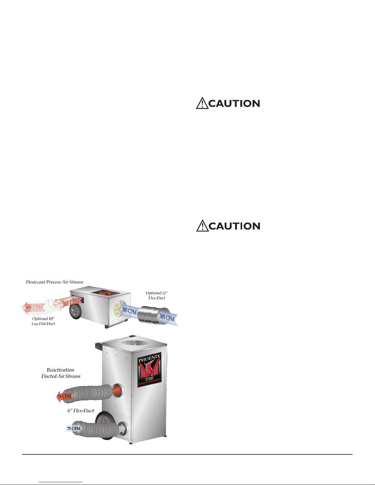
3.1 How the Phoenix D385 works
Your Phoenix D385 has two separate air streams that run
through it – Process (Fig. 1) and Reactivation (Fig. 2).
Note: Check for airflow at all inlets and outlets. DO NOT run
unit if no airflow is detected.
Process Air Stream:
P1 – 385 CFM of air enters (12”ex) the top of the machine
and...
P2 – ...water vapor from incoming air is deposited on the
desiccant wheel.
P3 – 385 CFM of dry air exits (10” lay at) the machine.
Reactivation Air Stream:
R1 – 75 CFM of air enters (6”ex) the lower-side of the
machine and...
R2 – passes over the heater coils.
R3 – Water vapor is picked up from the desiccant wheel by
the hot air and...
R4 – ...75 CFM of wet air exits (6”ex) the machine.
P3
P2
Figure 1: Desiccant process air stream.
R3
R2
R1
Figure 2: Desiccant reactivation air stream.
P1
Take care to prevent the reactivation exhaust air stream
from causing secondary damage due to condensation.
If the reactivation exhaust air stream cools below its
dewpoint liquid water will condense inside the duct work
creating puddles. If the reactivation exhaust air stream is not
exhausted completely from the structure it can also cause
secondary water damage.
Your Phoenix D385 does not produce liquid water internal
to the machine. There is no condensate pump and no drain
hose.
The D385 desiccant dehumidier will continue to remove
water from already dry, cold air. It is possible to over-dry
objects and or structures.
Care must be taken to avoid secondary damages due to
over-drying.
3.3 Electrical Requirements
When used on a water loss work site, ground fault circuit
interrupter (GFCI) outlets are required.
Your Phoenix D385 requires a total of 24 amps, 115VAC. In
order to run at all, this machine must be plugged into two
separate circuits each with a minimum of 12 amps dedicated
capacity available.
The D385 has two separate power cords, each cord must be
plugged into its own 15 amp circuit. If both cords are plugged
into the same 15 amp circuit this circuit will trip when the
unit is turned on.
Another situation to avoid is that one or both of the circuits
which the D385 is using can be tripped by other appliances
drawing power from either circuit. This can happen well
after a job site has been set-up as in the case with a freezer
compressor turning on.
Care must be taken to insure that the D385 always has
sufcient power available to run without tripping breakers or
blowing fuses.
If your location requires the use of an extension cord, use
safe techniques in selection and connection. Such cords
must be grounded and rated for carrying 12 amps: 14 gauge
minimum for one extension less than 25ft in length or 12
gauge for one extension less than 50ft in length.
3
www.UsePhoenix.com • sales@UsePhoenix.comToll-Free 1-800-533-7533
 Loading...