

Page 1
Wingspan : 2070 mm (81.5 inch)
Length : 1870 mm (73.6 inches)
Weight : 7000 g - 7500 g
Engine : Recommended DA 50 cc
Radio : 6 - 8 channels / 8 servos
g
Instruction Manual
nstruction Manu
Page 2
Instruction Manual
CAP 232
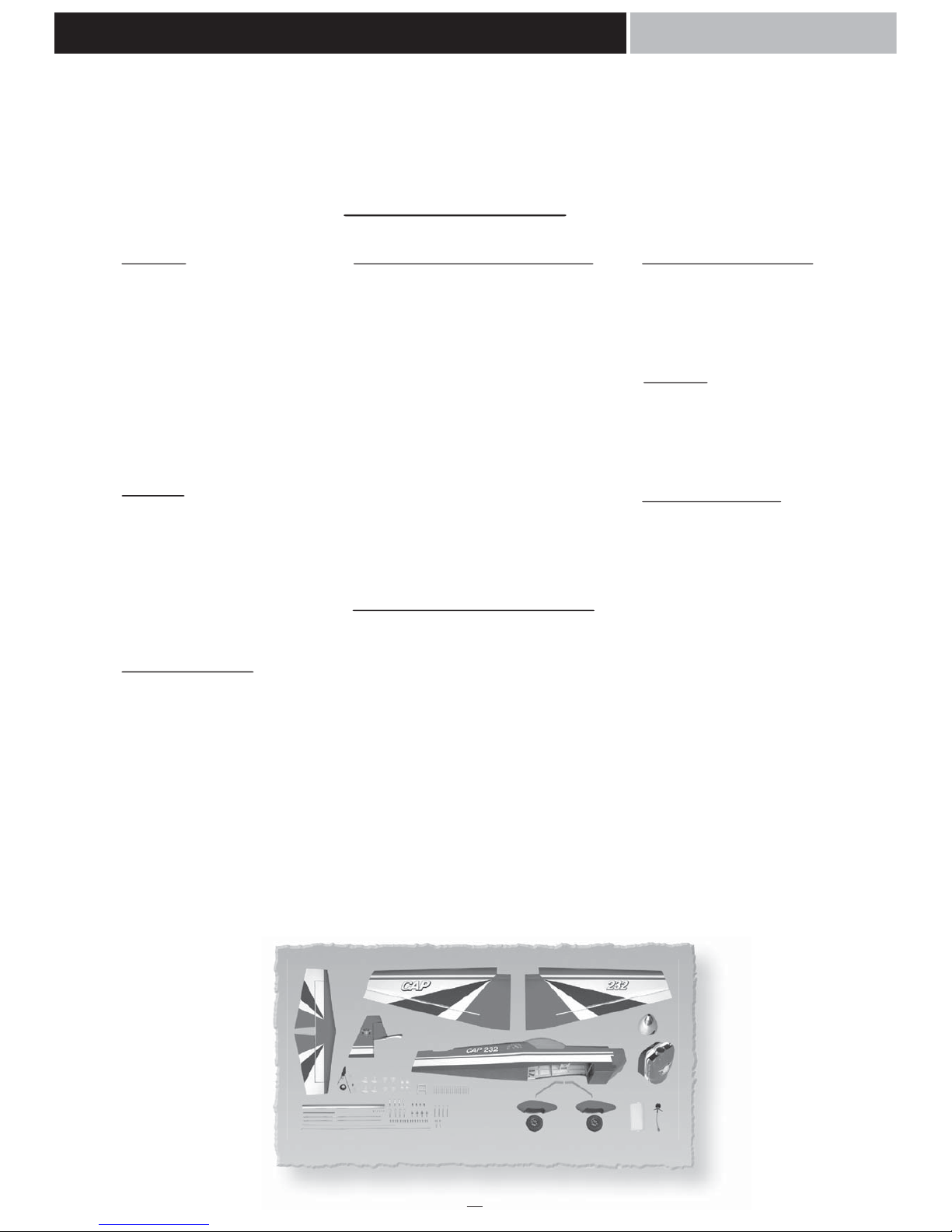
KIT CONTENTS: We have organized the parts as they come out of the box for better identification
during assembly. We recommend that you regroup the parts in the same manner. This will ensure you
have all of parts required before you begin assembly.
MAIN GEAR
(2) Main gear
(2) 100mm Wheel
(2) Wheel pant
(4) 6mm x 20mm screw
(4) 16mm washer
(6) Collar
(4) 3mm x 4mm screw
(2) 16mm washer
(2) Alxe
(2) 6mm nut
TAIL GEAR
(1) Tail gear
(1) 35mm wheel
(3) 3mm collar
(3) 3mm x 4mm screw
(2) Nylon clasp
(3) 2mm x 10mm screw
ELEVATOR CONTROL
AND LINKAGE SYSTEM
(6) 2mm x 30mm screw
(6) 2mm nut
(2) 3mm x 30mm screw
(2) 3mm nut
(2) Nylon clasp
(2) Nylon control horn A
(2) Nylon control horn B
(2) Metal clevis M3
(6) 3mm nut
(4) Metal connector M3
(2) Black nylon control
(2) Aluminum control
(2) 3mm x 12mm screw
(2) 6mm washer
THROTTLE CONTROL SYSTEM
(1) 1,3mm x 600mm metal rod
(1) 3,5mm x 350mm plastic tube
(1) Metal connector
(1) 4mm x 4mm screw
FUEL TANK
(1) Fuel tank
(1) Metal clunk
(1) Stopper
(1) 80mm x 125mm foam
MISCELLANEOUS ITEMS
(1) Aluminum dihedral
(2) 6mm x 40mm screw
(2) 16mm washer
(6) 2,6mm x 10mm screw
(1) 25mm x 600mm red trim tape
(1) 25mm x 600mm grey trim tape
(1) 800mm carbon rod
(4) 16mm washer
(1) Cowling
(1) Decal sheet
(1) Manuel book
RUDDER CONTROL AND LINKAGE system
(2) Nylon control horn A
(3) 2mm x 30mm screw
(3) 2mm nut
(2) 3mm x 30mm screw
(2) 3mm nut
(2) Nylon clasp
(2) 1200mm cable
(4) Lock metal
(4) Metal control
(12) 3mm nut
(4) Metal clevis M3
(4) 3mm x 12mm nut
(4) 6mm washer
(4) Black nylon control
(4) Aluminum control
(4) Metal connector M3
AILERON CONTROL AND LINKAGE SYSTEM
(4) Nylon control horn
(4) Nylon clasp
(4) 2mm x 30mm screw
(4) 2mm nut
(4) 3mm x 30mm screw
(4) 3mm nut
(8) 3mm x 35mm screw
(8) 3mm nut
(4) Black nylon control
(4) Aluminum control
(8) Metal connector M3
(8) 3mm nut
(4) Metal clevis M3
(4) 3mm x 12mm screw
(4) 6mm washer
(4) 3mm nut
KIT CONTENTS
1
Page 3
2
1 2
3 4
5 6
7 8
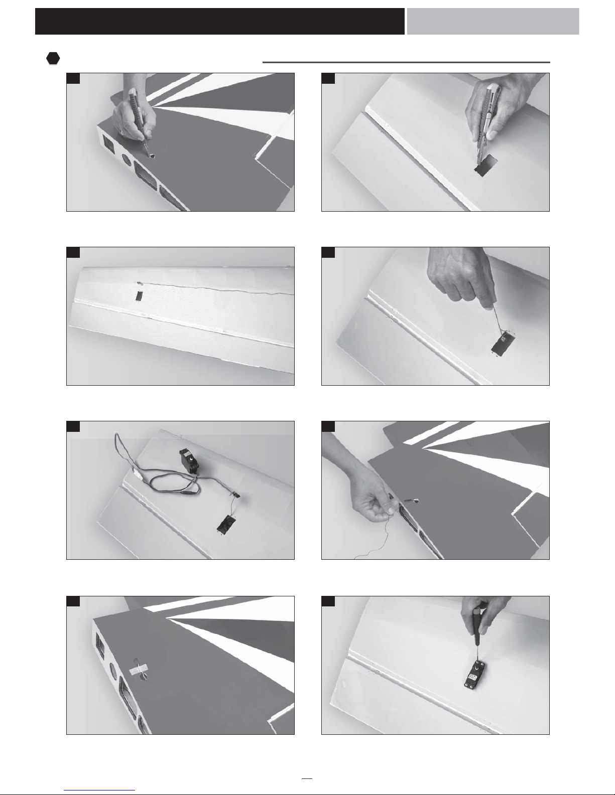
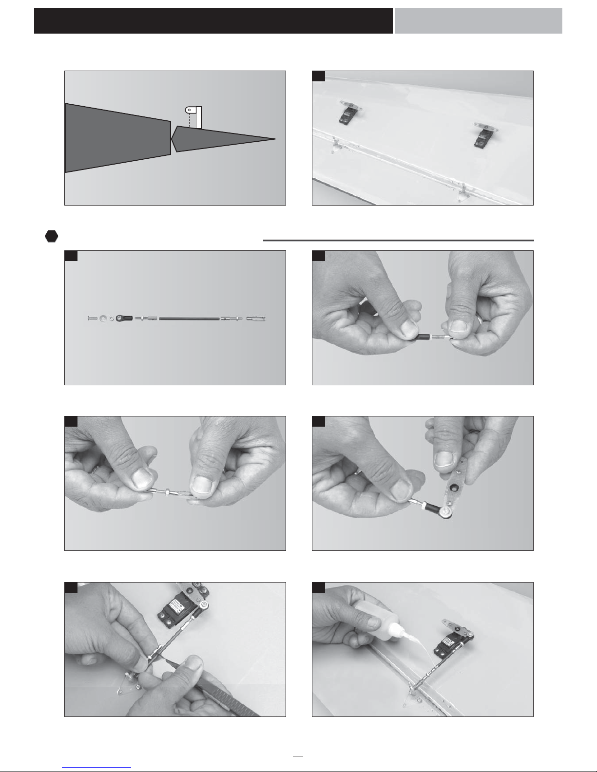
Remove the covering from the top of the wing. Remove the covering from the aileron servo box.
Using the collars and prepare the thread as a guide. Insert the thread into the wing.
Tape the servo lead into the end of the thread. Pull the servo lead out.
Using the masking tape, tape the servo lead onto the top of
the wing.
Secure the aileron servo.
Instruction Manual
CAP 232
Installing the aileron servos.
1
Page 4
3
9 10
11 12
13 14
15
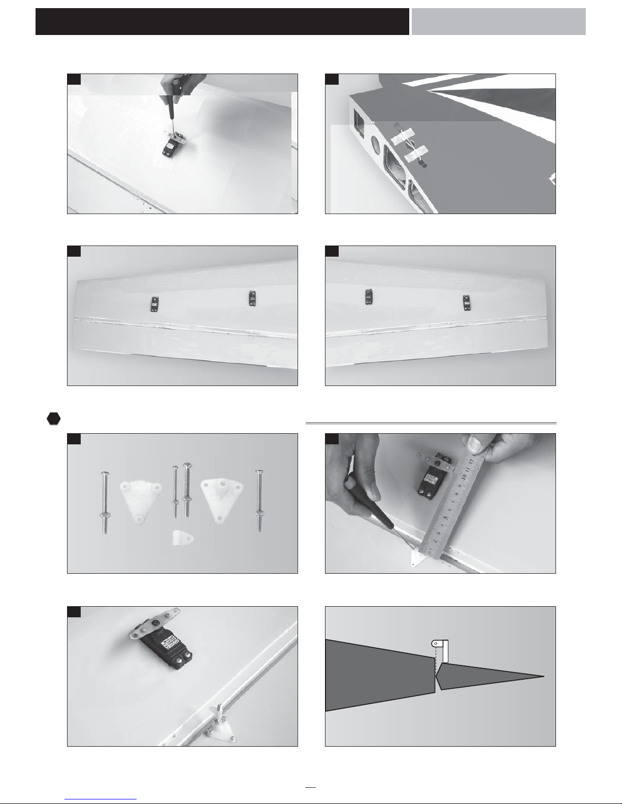
Make the same way to install the second aileron servo. Using the masking tape, tape the servo lead onto the top of
the wing.
Make the same way to install the second aileron servo. Make the same way to install two aileron servo for the
second wing.
The aileron control horn. Mark four holes from the control horn onto the bottom of
the aileron and INLINE with the servo arm.
Install the control horn and install the nylon control clasp.
Instruction Manual
CAP 232
Installing the aileron control horn.
2
Correct
Page 5
4
16
17 18
19 20
21 22
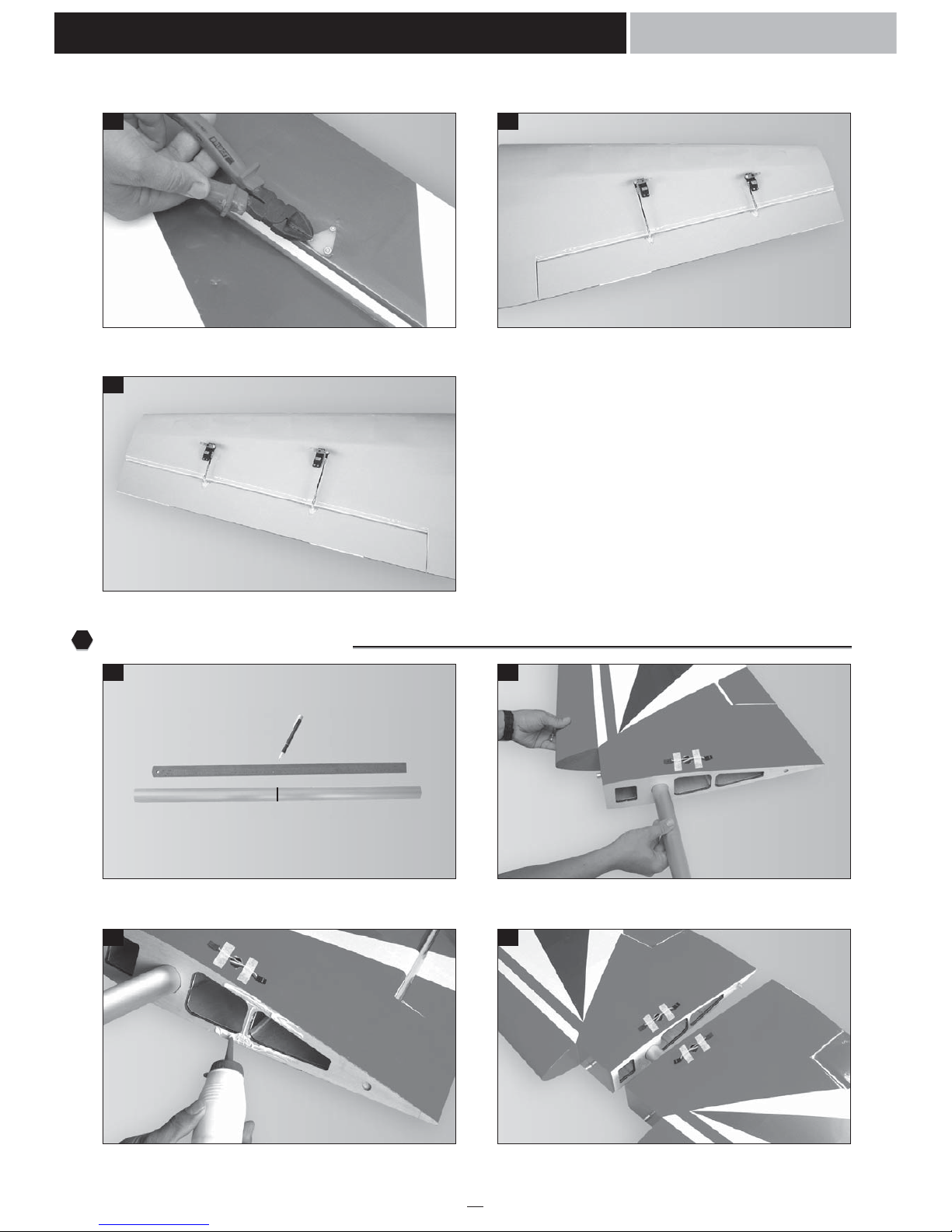
Make the same way to install the second control horn.
One set of the aileron pushrod. Attach the metal connector into the nylon clasp.
Attach the metal clevis into the metal connector. Install the nylon clasp into the servo arm.
Cut away the carbon fiber pushrod. Using the C.A glue - glue the aileron pushrod.
Instruction Manual
CAP 232
Installing the aileron linkages.
3
Wrong
Page 6
5
23 24
25
26 27
28 29
Cut away the screw. Make the same way to install the second aileron pushrod.
Make the same way for the second wing.
Draw a center line. Glue the wing joiner to the wing, using the epoxy glue.
Apply the epoxy onto the wing section. Joining the wing.
Instruction Manual
CAP 232
Joining the wing halves.
4
Center line
Page 7

6
30 31
32 33
34
35 36
Apply the trim tape to the center section of the wing
where they join.
Apply the trim tape to the center section of the wing where
they join.
Make a center line onto the horizontal. Remove the covering from the rear of the fuselage.
Attach the horizontal to the fuselage and check it.
Mark the shape of the fuselage onto the bottom of the
horizontal.
Remove the covering from the bottom of the horizontal.
Instruction Manual
CAP 232
Installing the horizontal stabilizer and the vertical stabilizer.
5
Center line
C1 C2
C1 = C2
Page 8

7
37 38
39 40
41 42
43
Remove the covering from the rear of the vertical. Remove the covering from the slot of the fuselage.
Attach the horizontal and the vertical to the fuselage and
insert the hinge into the slot.
Mark the shape of the vertical onto the top of the horizontal.
Remove the covering from the top of the horizontal. Glue the horizontal into the fuselage by epoxy.
Glue the vertical into the fuselage by epoxy and also glue
the hinge of rudder.
Instruction Manual
CAP 232
a1 a2
a1 = a2
Page 9

8
44
45 46
47 48
49 50
Finishing.
The tail gear. Install the wheel and the collars into the tail gear.
Make the slot onto the bottom of the rudder. Glue two nylon clasp by C.A glue into the rudder.
Install the tail gear. Secure the tail gear.
Instruction Manual
CAP 232
Installing the tail gear.
6
Page 10

9
51 52
53 54
55 56
57 58
The full set of the landing gear. Install the wheel into the axle.
Drill and cut the wheel pant. Install the axle, the wheel pant into the main gear and secure
them.
Remove the covering on the fuselage. Install the landing gear and secure it.
The control horn and linkages of the elevator. Remove the covering from the elevator servo box.
Instruction Manual
CAP 232
Installing the landing gear.
7
Installing the elevator linkages.
8
Page 11

10
59 60
61
62
63 64
Secure the elevator servo in place. Install the nylon control clasp.
Secure the control horn onto the elevator (Note: the control
must be INLINE with the servo arm the elevator servo).
Cut away the screw.
Attach the metal connector into the nylon control clasp. Attach the metal connector into the metal clevis.
Instruction Manual
CAP 232
Correct
Wrong
Page 12

11
65 66
67 68
69
70 71
Install the nylon clasp into the servo arm. Cut away the carbon fiber pushrod.
Secure the servo arm. Using the C.A glue - Glue the elevator pushrod.
Make the same way for the second elevator servo.
The control horn of the rudder. One cable set.
Instruction Manual
CAP 232
Installing the rudder linkages.
9
Page 13

12
72 73
74
75
76 77
Install the first control horn. Install the nylon control clasp.
Install two nylon control horn in place.
(Note: the nylon clasp must be level with the exits cable)
Cut away the screws.
Remove the covering from the slot. Prepare the cable.
Instruction Manual
CAP 232
Cable
Control horn
RIGHT
Cable
Control horn
LEFT
Page 14

13
78 79
80 81
82 83
84 85
Insert the cable into the plastic tube. Attach the metal clevis into the nylon control horn.
Lock the cable. Make the same way for the second cable.
Install the rudder servo. Install the servo arm.
Lock the cable. Install the second rudder servo.
Instruction Manual
CAP 232
Page 15

14
86 87
88
89 90
91 92
Prepare two carbon pushrod. Connect the second rudder servo into the first rudder servo.
Secure the servo arm.
Drill four holes for the engine mount. Install the engine mount.
Drill and install the plastic tube for throttle. Install the engine.
Instruction Manual
CAP 232
Installing the engine (In this section - we use the DA 50cc gas engine).
10
Page 16

15
93 94
95 96
97 98
99 100
Prepare the choke. Secure the muffler.
Cut away the fuel tube. Prepare the stopper for the tank.
Install the stopper to the tank. Secure the stopper.
Install the silicone tube of the tank (not included). Install the fuel tank in place and secure it.
Instruction Manual
CAP 232
Installing the fuel tank.
11
Page 17

16
101 102
103
104 105
106
Install the throttle servo. Install the metal connector.
Secure the throttle rod.
Install the radio switch. Install the engine switch (if neccessary).
Finishing.
Instruction Manual
CAP 232
Installing the throttle servo.
12
Installing the switch.
13
Battery
Receiver
Radio switch
Engine switch
Fuel tank
Page 18

17
107 108
109
109
110 111
112
Cut out the fiber glass (for cooling the engine). Glue the plywood into the fuselage.
Secure the cowling.
Screws. Remove the covering from the bottom and the top of the
wing.
Secure the wing.
Instruction Manual
CAP 232
Installing the cowling.
14
Installing the wing.
15
Plywood
Page 19

Instruction Manual
CAP 232
BALANCING
1. It is critical that your airplane be balanced correctly.
Improper balance will cause your plane to lose
control and crash.
THE CENTER OF GRAVITY IS LOCATED 150mm
BACK FROM THE LEADING EDGE OF THE
WING, AT THE FUSELAGE.
2. Mount the wing to the fuselage. Using a couple of
pieces of masking tape, place them on the top side
of the wing 150mm back from the leading edge, at
the fuselage sides.
3. Turn the airplane upside down. Place your fingers on
the masking tape and carefully lift the plane .
4. If the nose of the plane falls, the plane is nose
heavy. To correct this first move the battery pack
further back in the fuselage. If this is not possible or
does not correct it, stick small amounts of lead
weight on the fuselage under the horizontal
stabilizer. If the tail of the plane falls, the plane is tail
heavy. To correct this, move the battery and
receiver forward or if this is not possible, stick
weight into the firewall. When balanced correctly,
the airplane should sit level or slightly nose down
when you lift it up with your fingers.
CONTROL THROWS
1. We highly recommend setting up a plane using the
control throws listed.
2. The control throws should be measured at the widest
point of each control surface.
3. Check to be sure the control surfaces move in the
correct directions.
150mm
Aileron 35mm up 35mm down
Elevator 70mm up 70mm down
Rudder 60mm right 60mm left
Elevator Control
Aileron Control
35mm
35mm
Rudder Control
60mm
60mm
70mm
70mm
LATERAL BALANCE
After you have balanced a plane on the C.G. You
should laterally balance it. Doing this will help the
airplane track straighter.
1. Turn the airplane upside down. Attach one loop of
heavy string to the engine crankshaft and one to the
tail wheel wire. With the wings level, carefully lift
the airplane by the string. This may require two
people to make it easier.
2. If one side of the wing fall, that side is heavier than
the opposite. Add small amounts of lead weight to
the bottom side of the lighter wing half's wing tip.
Follow this procedure until the wing stays level
when you lift the airplane.
!!!
FLIGHT PREPARATION PRE FLIGHT CHECK
1. Completely charge your transmitter and receiver
batteries before your first day of flying.
2. Check every bolt and every glue joint in your plane
to ensure that everything is tight and well bonded.
3. Double check the balance of the airplane
4. Check the control surface
5. Check the receiver antenna . It should be fully
extended and not coiled up inside the fuselage.
6. Properly balance the propeller.
Aileron 70mm up 70mm down
Elevator 110mm up 110mm down
Rudder 130mm right 130mm left
High rate:
Low rate:
18
Page 20

 Loading...