

Page 1
Instruction Manual
Instruction Manual
TOOLS AND SUPPLIES NEEDED.
• Medium C/A glue.
• 30 minute epoxy.
• 6 minute epoxy.
• Hand or electric drill.
• Assorted drill bits.
• Modeling knife.
• Straight edge ruler.
• 2 bender plier.
• Wire cutters.
• Masking tape.
• Thread lock.
• Paper towels.
• Rubbing alcohol
SUGGESTION
To avoid scratching your new airplane, do not unwrap
the pieces until they are needed for assembly. Cover
your workbench with an old towel or brown paper,
both to protect the aircraft and to protect the table.
Keep a couple of jars or bowls handy to hold the
small parts after you open the bag.
NOTE:
Please trial fit all the parts. Make sure you have the
correct parts and that they fit and are aligned properly
before gluing! This will assure proper assembly. The
ASK-21 ELECTRIC 3200 ARF 1/5 SCALE is hand
made from natural materials, every plane is unique
and minor adjustments may have to be made.
However, you should find the fit superior and
assembly simple.
The painted and plastic parts used in this kit are fuel
proof. However, they are not tolerant of many harsh
chemicals including the following: paint thinner, C/A
glue accelerator, C/A glue debonder and acetone. Do
not let these chemicals come in contact with the
colors on the covering and the plastic parts.
SAFETY PRECAUTION:
• This is not a toy
• Be sure that no other flyers are using your radio
frequency.
• Do not smoke near fuel
• Store fuel in a cool, dry place, away from
children and pets.
• Wear safety glasses.
• The glow plug clip must be securely attached to
the glow plug.
• Do not flip the propeller with your fingers.
• Keep loose clothing and wires away from the propeller.
• Do not start the engine if people are near. Do not
stand in line with the side of the propeller.
• Make engine adjustments from behind the propeller
only. Do not reach around the spinning propeller.
I n s t r u c t i o n M a n u a l
- Control throw Ailerons: Low: 10mm up/down,
10% expo; High: 12mm up/down, 10% expo
- Control throw Elevators: Low: 8mm up/down,
12% expo; High: 12mm up/down, 12% expo
- Control throw Rudder: Low: 30mm right/left,
15% expo; High: 55mm right/left, 15% expo
- Motor: brushless outrunner 700-800 W, 750 KV
- Experience level: Intermediate
- Plane type: Scale sailplane
RECOMMENDED MOTOR AND BATTERY SET UP
- Motor: OS OMA – 3825-750 (Not included)
- Propeller: 12x8 ; 13x8 (not included)
- Lipo cell: 3-4 cells / 2400 – 3000mAh (not included)
- Esc: 50-80 A (not included)
SPECIFICATION
- Wingspan: 3200mm (125,9 in)
- Length: 1650mm (64,9 in)
- Flying weight: 3000gr – 3200gr
- Wing area: 64.5 dm2
- Wing loading: 46g/dm2
- Wing type: HQ profile
- Radio: 4 channel – 4 mini hi-torque servo :
2 aileron; 1 elevator; 1 rudder (not included)
- Servo mount : 12mm X 24mm
- Flap: 2 electric flaps 440mm (not included)
- Spinner size: Aluminum H hub propeller
holder, shaft 6mm (not included)
- Propeller: suit with your engine
- Gravity CG: 75 mm (2.95 in) Back from the
leading edge of the wing, at the fuselage
Page 2
Instruction Manual
ASK-21 ELECTRIC 3200
Instruction Manual
1
TOOLS AND SUPPLIES NEEDED.
• Medium C/A glue.
• 30 minute epoxy.
• 6 minute epoxy.
• Hand or electric drill.
• Assorted drill bits.
• Modeling knife.
• Straight edge ruler.
• 2 bender plier.
• Wire cutters.
• Masking tape.
• Thread lock.
• Paper towels.
• Rubbing alcohol
SUGGESTION
To avoid scratching your new airplane, do not unwrap
the pieces until they are needed for assembly. Cover
your workbench with an old towel or brown paper,
both to protect the aircraft and to protect the table.
Keep a couple of jars or bowls handy to hold the
small parts after you open the bag.
NOTE:
Please trial fit all the parts. Make sure you have the
correct parts and that they fit and are aligned properly
before gluing! This will assure proper assembly. The
ASK-21 ELECTRIC 3200 ARF 1/5 SCALE is hand
made from natural materials, every plane is unique
and minor adjustments may have to be made.
However, you should find the fit superior and
assembly simple.
The painted and plastic parts used in this kit are fuel
proof. However, they are not tolerant of many harsh
chemicals including the following: paint thinner, C/A
glue accelerator, C/A glue debonder and acetone. Do
not let these chemicals come in contact with the
colors on the covering and the plastic parts.
SAFETY PRECAUTION:
• This is not a toy
• Be sure that no other flyers are using your radio
frequency.
• Do not smoke near fuel
• Store fuel in a cool, dry place, away from
children and pets.
• Wear safety glasses.
• The glow plug clip must be securely attached to
the glow plug.
• Do not flip the propeller with your fingers.
• Keep loose clothing and wires away from the propeller.
• Do not start the engine if people are near. Do not
stand in line with the side of the propeller.
• Make engine adjustments from behind the propeller
only. Do not reach around the spinning propeller.
PREPARATIONS
Remove the tape and separate the ailerons from
the wing and the elevators from the stab. Use a
covering iron with a covering sock on high heat to
tighten the covering if necessary. Apply pressure
over sheeted areas to thoroughly bond the
covering to the wood.
1
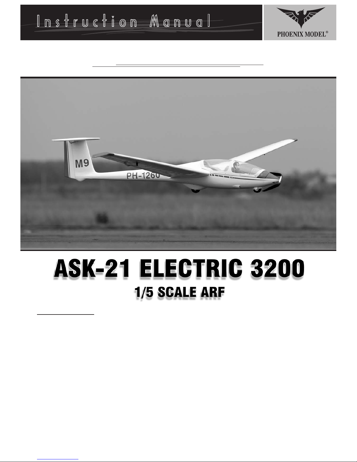
INSTALLING THE AILERONS
1. Test fit the ailerons to the wing with the hinges.
If the hinges don’t remain centered, stick a pin
through the middle of the hinge to hold it in
position.
TEMPORARY PIN
TO KEEP HINGE
CENTERED
2
CA glue
2. Apply six drops of thin CA to the top and bottom
of each hinge. Do not use CA accelerator. After
the CA has fully hardened, test the hinges by
pulling on the aileron.
3. Place the servo into the servo tray. Center the
INSTALLING THE AILERON SERVOS
1. Install the rubber grommets and brass eyelets
2. Using a modeling knife, remove the covering
4. Using the thread as a guide and using masking
Page 3
Instruction Manual
ASK-21 ELECTRIC 3200
Instruction Manual
2
3. Place the servo into the servo tray. Center the
servo within the tray and drill 1,6mm pilot holes
through the block of wood for each of the four
mounting screws provided with the servo.
Remove the covering
3
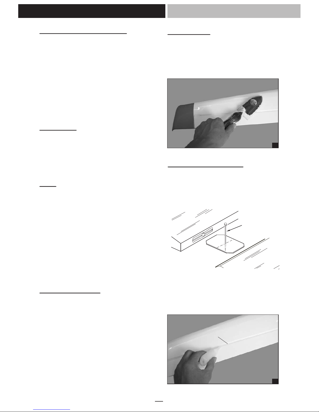
INSTALLING THE AILERON SERVOS
1. Install the rubber grommets and brass eyelets
onto the aileron servo.
2. Using a modeling knife, remove the covering
from over the pre-cut servo arm exit hole on the
aileron servo tray / hatch. This hole will allow
the servo arm to pass through when installing
the aileron pushrods.
4
6. Repeat step # 2 - # 5 to install the second
aileron servo in the opposite wing half.
5. Place the aileron servo tray / hatch into the
servo box on the bottom of the wing and drill
1,6mm pilot holes through the tray and the
servo box for each of the four mounting screws.
Secure the servo tray in place using the
mounting screws provided ( 2mm x 12mm ).
4. Using the thread as a guide and using masking
tape, tape the servo lead to the end of the
thread: carefully pull the thread out. When you
have pulled the servo lead out, remove the
masking tape and the servo lead from the
thread.
Servo lead
5
6
7
2. Attach the clevis to the outer hole in the control
3. Locate one nylon servo arm, and using wire
4. Plug the aileron servo into the receiver and
5. Center the aileron and hold it in place using a
6. With the aileron and aileron servo centered,
7. Using pliers, carefully make a 90 degree bend
8. Insert the 90 degree bend down through the
INSTALLING THE AILERON LINKAGES
1. Working with the aileron linkage for now, thread
8
3. Repeat step # 1 - # 2 to install the control horn
INSTALLING THE CONTROL HORNS
1. One aileron control horn in positioned on each
aileron. Using a ruler and a pen, locate and
mark the location of the control horn. It should
be mounted on the bottom side of the aileron at
the leading edge, in line with the aileron
pushrod.
2. Drill two 1.6mm holes through the aileron using
the control horn as a guide and screw the
control horn in place.
Page 4
Instruction Manual
ASK-21 ELECTRIC 3200
Instruction Manual
3
9. Repeat step # 4 - # 8 to install the second
aileron linkage. After both linkages are
completed, connect both of the aileron servo
leads using a Y-harness you have purchased
separately.
11
12
Silicone Tube
10
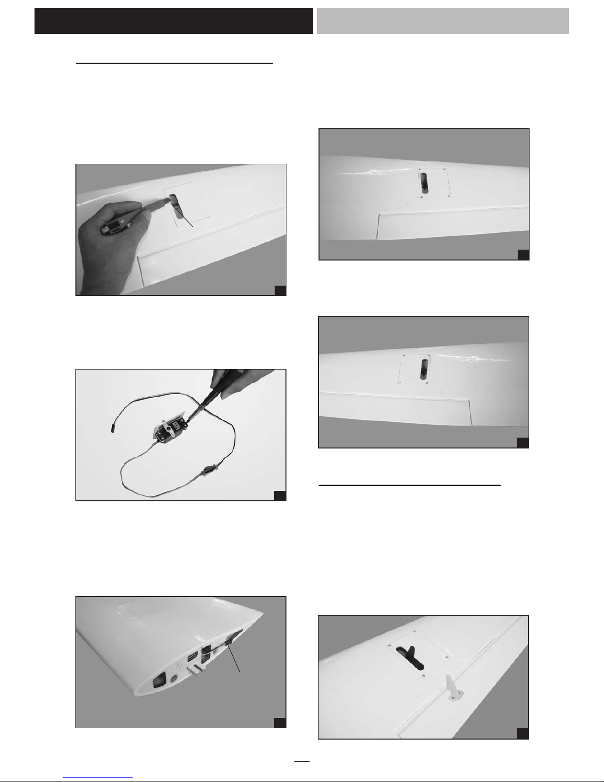
2. Attach the clevis to the outer hole in the control
horn. Install a silicone tube on the clevis.
3. Locate one nylon servo arm, and using wire
cutters, remove all but one of the arms. Using a
2mm drill bit, enlarge the third hole out from the
center of the arm to accommodate the aileron
pushrod wire.
4. Plug the aileron servo into the receiver and
center the servo. Install the servo arm onto the
servo. The servo arm should be perpendicular
to the servo and point toward the middle of the
wing.
5. Center the aileron and hold it in place using a
couple of pieces of masking tape.
6. With the aileron and aileron servo centered,
carefully place a mark on the aileron pushrod
wire where it crosses the hole in the servo arm.
7. Using pliers, carefully make a 90 degree bend
down at the mark made. Cut off the excess
wire, leaving about 4mm beyond the bend.
8. Insert the 90 degree bend down through the
hole in the servo arm. Install one nylon snap
keeper over the wire to secure it to the arm.
Install the servo arm retaining screw and
remove the masking tape from the aileron.
INSTALLING THE AILERON LINKAGES
1. Working with the aileron linkage for now, thread
one nylon clevis at least 14 turns onto one of
the 2mm x 180mm threaded wires.
9
INSTALLING THE WING
1. Attach the wing to the fuselage as picture.
3. Repeat step # 1 - # 2 to install the control horn
on the opposite aileron.
RIGHT WRONG
13
WING TIP
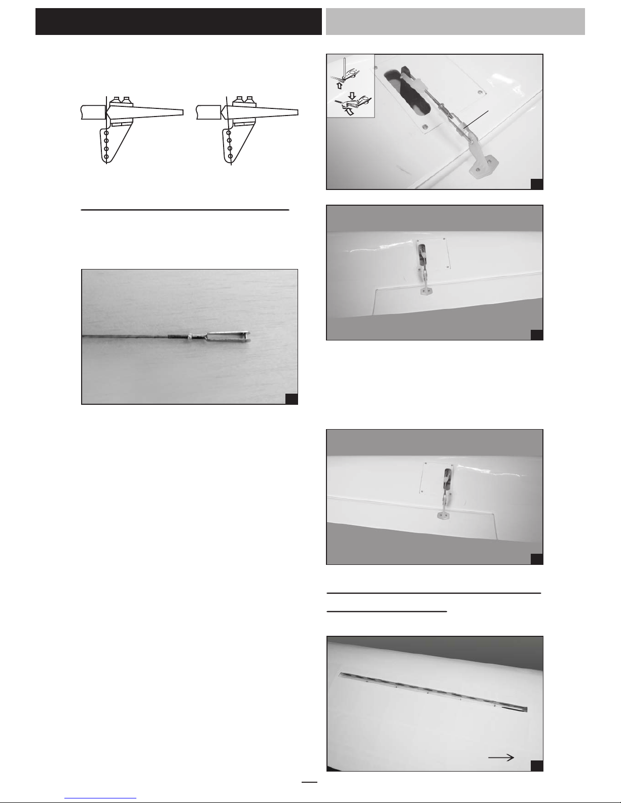
INSTALLING THE electric air brakes
(not included with the kit)
1. Remove the covering from the top of the wing.
2. Install the air brake into the bay.
2. Slide the joiner to the wing and to the fuselage.
3. Secure the wing.
Page 5

Instruction Manual
ASK-21 ELECTRIC 3200
Instruction Manual
4
4. Test the position of the elevator and adjust it as
shown.
18
Screw
17
Dihedral brace
16
Remove the covering
20
INSTALLING THE main landing gear
1. The full set wheel.
INSTALLING THE WING
1. Attach the wing to the fuselage as picture.
19
2. Secure the collars.
3. Glue the wooden plate to the fuselage.
14
WING TIP
15
WING TIP
2. Install the air brake into the bay.
2. Slide the joiner to the wing and to the fuselage.
3. Secure the wing.
Page 6

Instruction Manual
ASK-21 ELECTRIC 3200
23
24
25
26
27
5
INSTALLING THE ELEVATOR
- Repeat step #1 - #2 from installing the aileron
to install the elevator.
3. Glue the wooden plate to the fuselage.
INSTALLING THE CONTROL HORNS
AND LINKAGES
Repeat these step as installing the aileron control
horn and linkages.
21
CA glue
CA glue
CA glue
CA glue
CA glue
Trim the plastic
22
Remove the plastic
Page 7

Instruction Manual
ASK-21 ELECTRIC 3200
Instruction Manual
6
28
Remove the covering
29
30
32
31
Control horn elevator
33
Servo lead
34
Screw
INSTALLING THE RUDDER
Repeat these step from installing the aileron to
install the rudder.
INSTALLING THE CONTROL HORN AND
LINKAGE.
Repeat these step as installing the aileron control
horn and linkages.
35
Secure the servo.
Secure the servo to the plate.
Install the push rod linkages.
Secure the horizontal stabilizer to the fuselage.
Secure the elevator servo mount
Page 8

Instruction Manual
ASK-21 ELECTRIC 3200
Instruction Manual
7
INSTALLING THE CONTROL HORN AND
LINKAGE.
Repeat these step as installing the aileron control
horn and linkages.
INSTALLING THE towing servo
1. Install the metal connector to the servo arm.
2. Bend “L” the metal rod as the picture below.
3. Place the servo arm to the servo and secure it.
42
43
36
37
38
39
40
41
Remove the covering
Servo lead
Remove the covering
CA glue
CA glue
Secure the servo to the plate.
Slide the servo lead to the fuselage.
Secure the rudder servo mount.
Secure the control horn.
Install the push rod linkage.
Page 9

Instruction Manual
ASK-21 ELECTRIC 3200
Instruction Manual
44
INSTALLING THE towing servo
1. Install the metal connector to the servo arm.
2. Bend “L” the metal rod as the picture below.
3. Place the servo arm to the servo and secure it.
8
45
46
!
INSTALLING THE RECEIVER AND BATTERY
1. Plug the servo leads and the switch lead into
the receiver. You may want to plug an aileron
extension into the receiver to make plugging in
the aileron servo lead easier when you are
installing the wing. Plug the battery pack lead
into the switch.
2. Wrap the receiver and battery pack in the
protective foam to protect them from vibration.
Use a rubber band or masking tape to hold the
foam in place.
Do not permanently secure the receiver and
battery until after balancing the model.
INSTALLING THE MOTOR
47
48
49
Remove the covering
CA glue
Line
Wooden engine mount.
Secure the motor and the connector.
Page 10

Instruction Manual
ASK-21 ELECTRIC 3200
Instruction Manual
50
Screw
51
52
ESC
Battery
9
- Glue the plastic cover to the fuselage.
BALANCING
1. It is critical that your airplane be balanced
correctly. Improper balance will cause your
plane to lose control and crash.
THE CENTER OF GRAVITY IS LOCATED 75mm
BACK FROM THE LEADING EDGE OF THE
WING, AT THE FUSELAGE. This location is
recommended for initial test flying and
trimming. BALANCE A PLANE UPSIDE DOWN
WITH THE FUEL TANK EMPTY.
2. Mount the wing to the fuselage. Using a couple
of pieces of masking tape, place them on the
top side of the wing 75mm back from the
leading edge, at the fuselage sides.
3. Turn the airplane upside down. Place your
fingers on the masking tape and carefully lift
the plane .
4. If the nose of the plane falls, the plane is nose
heavy. To correct this first move the battery
pack further back in the fuselage. If this is not
possible or does not correct it, stick small
amounts of lead weight on the fuselage under
the horizontal stabilizer. If the tail of the plane
falls, the plane is tail heavy. To correct this,
move the battery and receiver forward or if this
is not possible, stick weight into the firewall.
When balanced correctly, the airplane should
sit level or slightly nose down when you lift it up
with your fingers.
RECOMMENDED MOTOR AND BATTERY SET UP
- Motor: OS OMA – 3825-750 (Not included)
- Propeller: 12x8 ; 13x8 (not included)
- Lipo cell: 3-4 cells / 3200 – 4000mAh
(not included)
- Esc: 50-80 A (not included)
!
LATERAL BALANCE
After you have balanced a plane on the C.G.
5. Turn the airplane upside down. Attach one loop
6. If one side of the wing fall, that side is heavier
54
CONTROL THROWS
1. We highly recommend setting up a plane using
2. The control throws should be measured at the
3. Check to be sure the control surfaces move in
CA glue
53
Glue the plastic air cooler
Page 11

Instruction Manual
ASK-21 ELECTRIC 3200
75mm
!
LATERAL BALANCE
After you have balanced a plane on the C.G.
You should laterally balance it. Doing this will
help the airplane track straighter.
5. Turn the airplane upside down. Attach one loop
of heavy string to the engine crankshaft and
one to the tail wheel wire. With the wings level,
carefully lift the airplane by the string. This may
require two people to make it easier.
6. If one side of the wing fall, that side is heavier
than the opposite. Add small amounts of lead
weight to the bottom side of the lighter wing
half's wing tip. Follow this procedure until the
wing stays level when you lift the airplane.
10
CONTROL THROWS
1. We highly recommend setting up a plane using
the control throws listed.
2. The control throws should be measured at the
widest point of each control surface.
3. Check to be sure the control surfaces move in
the correct directions.
Aileron Control
10mm
10mm
Rudder Control
30mm
30mm
Elevator Control
8mm
8mm
FLIGHT PREPARATION
PRE FLIGHT CHECK
1. Completely charge your transmitter and receiver
batteries before your first day of flying.
2. Check every bolt and every glue joint in your
plane to ensure that everything is tight and well
bonded.
3. Double check the balance of the airplane.
4. Check the control surface.
5. Check the receiver antenna . It should be fully
extended and not coiled up inside the fuselage.
6. Properly balance the propeller.
Aileron : 10mm up 10mm down
Elevator : 8mm up 8mm down
Rudder : 30mm right 30 mm left
Page 12

I/C FLIGHT GUIDELINES
When ready to fly, first extend the
transmitter aerial.
Operate the control sticks on the
transmitter and check that the control
surfaces move freely and in the
CORRECT directions.
ALWAYS land the model INTO the
wind, this ensures that the model lands
at the slowest possible speed.
Switch on the transmitter.
Switch off the transmitter.
Check that the transmitter batteries
have adequate power.
Switch off the receiver.
Switch on the receiver.
ALWAYS take off into the wind.
Check that the wings are correctly
fitted to the fuselage.
If the model does not respond correctly
to the controls, land it as soon as
possible and correct the fault.
Empty the fuel tank after flying, fuel left
in the tank can cause corrosion and
lead to engine problems.
Made in Vietnam
 Loading...