

Page 1

Advanced Pressure Monitor II
and Central Display Rough-In
Installation Guide
Page 2

Copyright 2011, 2012, 2013
Phoenix Controls
Accel, Phoenix, Phoenix Controls, Usage Based Controls, UBC, Celeris, Theris, Traccel, Zone Presence
Sensor and ZPS are registered trademarks, and LabPro, MacroServer, MicroServer and Neutralizer
are trademarks of Honeywell International, Inc.
Phoenix Controls products are covered by one or more of the following U.S. patents:
5,251,665 5,304,093 5,545,086 D642894
and other patents pending.
The material in this document is for information purposes only and is subject to change without
notice. Phoenix Controls assumes no responsibility for any errors or for consequential damages that
may result from the use or misrepresentation of any of the material in this publication.
BACnet is a registered trademark of the American Society of Heating, Refrigerating, and AirConditioning Engineers (ASHRAE).
Printed in USA
Page 3

APM2 Rough-In Installation Guide
Table of Contents
Section 1. Advanced Pressure Monitor II Rough-In Installation
1.1 Required Parts to be Supplied by the Installer . . . . . . . . . . . . . . . . . . . . . . . . . . . . . . . . . . . . . . 1
1.2 Parts Included with Your Order . . . . . . . . . . . . . . . . . . . . . . . . . . . . . . . . . . . . . . . . . . . . . . . . . . 2
1.3 Installation Overview. . . . . . . . . . . . . . . . . . . . . . . . . . . . . . . . . . . . . . . . . . . . . . . . . . . . . . . . . . 2
1.3.1 Wiring Recommendations . . . . . . . . . . . . . . . . . . . . . . . . . . . . . . . . . . . . . . . . . . . . . . . . . . . . . . . . . 3
1.3.2 Wiring Triple Gang Electrical Box. . . . . . . . . . . . . . . . . . . . . . . . . . . . . . . . . . . . . . . . . . . . . . . . . . . . 4
1.3.3 Plumbing Rough-In. . . . . . . . . . . . . . . . . . . . . . . . . . . . . . . . . . . . . . . . . . . . . . . . . . . . . . . . . . . . . . . 4
1.3.4 Use of External Transducers . . . . . . . . . . . . . . . . . . . . . . . . . . . . . . . . . . . . . . . . . . . . . . . . . . . . . . . 5
1.3.5 Remote Annunicator . . . . . . . . . . . . . . . . . . . . . . . . . . . . . . . . . . . . . . . . . . . . . . . . . . . . . . . . . . . . . 6
1.4 Plumbing (Finish). . . . . . . . . . . . . . . . . . . . . . . . . . . . . . . . . . . . . . . . . . . . . . . . . . . . . . . . . . . . . 6
1.5 Wiring . . . . . . . . . . . . . . . . . . . . . . . . . . . . . . . . . . . . . . . . . . . . . . . . . . . . . . . . . . . . . . . . . . . . . 7
1.5.1 Power, Labeled POWER, L1, L2, Ground Symbol . . . . . . . . . . . . . . . . . . . . . . . . . . . . . . . . . . . . . . . 8
1.5.2 Analog Output, Labeled ANL OUT. . . . . . . . . . . . . . . . . . . . . . . . . . . . . . . . . . . . . . . . . . . . . . . . . . . 8
1.5.3 Analog Input, Labeled DOOR, INPUT2, INPUT1 . . . . . . . . . . . . . . . . . . . . . . . . . . . . . . . . . . . . . . . . 9
1.5.3.1 Measuring Analog Inputs. . . . . . . . . . . . . . . . . . . . . . . . . . . . . . . . . . . . . . . . . . . . . . . . . . . . . 9
1.5.4 Optional Remote Transducer Wiring . . . . . . . . . . . . . . . . . . . . . . . . . . . . . . . . . . . . . . . . . . . . . . . . . 9
1.5.5 Relay and Annunciator Output, Labeled RELAY . . . . . . . . . . . . . . . . . . . . . . . . . . . . . . . . . . . . . . . . 10
1.5.6 Optional Remote Annunciator Wiring . . . . . . . . . . . . . . . . . . . . . . . . . . . . . . . . . . . . . . . . . . . . . . . . 10
1.5.7 Third Party Remote Annunciator . . . . . . . . . . . . . . . . . . . . . . . . . . . . . . . . . . . . . . . . . . . . . . . . . . . . 11
1.5.8 Completing the Finish Wiring. . . . . . . . . . . . . . . . . . . . . . . . . . . . . . . . . . . . . . . . . . . . . . . . . . . . . . . 11
Section 2. Fitting an APM2 in an APM100 Enclosure
2.1 Overview . . . . . . . . . . . . . . . . . . . . . . . . . . . . . . . . . . . . . . . . . . . . . . . . . . . . . . . . . . . . . . . . . . 13
2.1.1 What Is Included In Your Kit . . . . . . . . . . . . . . . . . . . . . . . . . . . . . . . . . . . . . . . . . . . . . . . . . . . . . . . 13
2.1.1.1 Not Included - Tools You Will Need . . . . . . . . . . . . . . . . . . . . . . . . . . . . . . . . . . . . . . . . . . . . . 13
2.2 Instructions . . . . . . . . . . . . . . . . . . . . . . . . . . . . . . . . . . . . . . . . . . . . . . . . . . . . . . . . . . . . . . . . . 14
2.2.1 Turn Off Power To the APM100 Unit And Remove It From The Wall . . . . . . . . . . . . . . . . . . . . . . . . 14
2.2.2 Ensure Existing APM1 Enclosure Is Prepared For APM2 Unit. . . . . . . . . . . . . . . . . . . . . . . . . . . . . . 15
2.2.3 Attach the Base APM2 Unit. . . . . . . . . . . . . . . . . . . . . . . . . . . . . . . . . . . . . . . . . . . . . . . . . . . . . . . . 15
2.2.4 Wiring. . . . . . . . . . . . . . . . . . . . . . . . . . . . . . . . . . . . . . . . . . . . . . . . . . . . . . . . . . . . . . . . . . . . . . . . . 16
2.2.5 Remotely Switching Alarm Setpoints . . . . . . . . . . . . . . . . . . . . . . . . . . . . . . . . . . . . . . . . . . . . . . . . 16
2.2.6 Modified Pressure Taps . . . . . . . . . . . . . . . . . . . . . . . . . . . . . . . . . . . . . . . . . . . . . . . . . . . . . . . . . . . 17
2.2.7 Complete the Installation . . . . . . . . . . . . . . . . . . . . . . . . . . . . . . . . . . . . . . . . . . . . . . . . . . . . . . . . . . 17
Section 3. APM2 Central Display Rough-In Installation
3.1 Required Parts to be Supplied by the Installer . . . . . . . . . . . . . . . . . . . . . . . . . . . . . . . . . . . . . . 19
3.2 Parts included with Your Order . . . . . . . . . . . . . . . . . . . . . . . . . . . . . . . . . . . . . . . . . . . . . . . . . . 19
3.3 Installation Overview . . . . . . . . . . . . . . . . . . . . . . . . . . . . . . . . . . . . . . . . . . . . . . . . . . . . . . . . . 19
3.3.1 Wiring Recommendations . . . . . . . . . . . . . . . . . . . . . . . . . . . . . . . . . . . . . . . . . . . . . . . . . . . . . . . . . 20
3.3.2 Wiring Triple Gang Electrical Box. . . . . . . . . . . . . . . . . . . . . . . . . . . . . . . . . . . . . . . . . . . . . . . . . . . . 21
3.4 Wiring . . . . . . . . . . . . . . . . . . . . . . . . . . . . . . . . . . . . . . . . . . . . . . . . . . . . . . . . . . . . . . . . . . . . . 22
iii
MKT-0262 MPC-1748 Rev 02/13
Page 4

Table of Contents
3.4.1 Power, Labeled POWER, L1, L2, Ground Symbol . . . . . . . . . . . . . . . . . . . . . . . . . . . . . . . . . . . . . . . 22
3.4.2 Completing the Finish Wiring. . . . . . . . . . . . . . . . . . . . . . . . . . . . . . . . . . . . . . . . . . . . . . . . . . . . . . . 23
Section 4. Ancillary Product Specifications
4.1 Model 264 Pressure Transducer . . . . . . . . . . . . . . . . . . . . . . . . . . . . . . . . . . . . . . . . . . . . . . . . . 25
4.2 Model 267 Pressure Transducer . . . . . . . . . . . . . . . . . . . . . . . . . . . . . . . . . . . . . . . . . . . . . . . . . 28
4.3 Remote Annunciator. . . . . . . . . . . . . . . . . . . . . . . . . . . . . . . . . . . . . . . . . . . . . . . . . . . . . . . . . . 31
4.4 Pressure Pickup Port. . . . . . . . . . . . . . . . . . . . . . . . . . . . . . . . . . . . . . . . . . . . . . . . . . . . . . . . . . 32
4.5 Phoenix Recommended Cables . . . . . . . . . . . . . . . . . . . . . . . . . . . . . . . . . . . . . . . . . . . . . . . . . 33
4.5.1 MS/TP Specifications for Alternate Cable Solutions . . . . . . . . . . . . . . . . . . . . . . . . . . . . . . . . . . . . . 35
iv
MKT-0262 MPC-1748 Rev 02/13
Page 5

APM2 Rough-In Installation Guide
Advanced Pressure Monitor II Rough-In Installation
Required Parts to be Supplied by the Installer
Section 1. Advanced Pressure Monitor II Rough-In Installation
For the Advanced Pressure Monitor II (APM2) to be installed correctly, the rough-in phase of the project must
be completed properly. This section will outline the specific considerations the General Contractor must pay
attention to so that the final wiring and commissioning will go smoothly.
During rough-in installation, the field wiring and plumbing can be run in the walls and routed between the
triple gang electrical box, the Building Management System (BMS), door contact switch, remote sensors (if
applicable) power supply, earth ground and so on.
If you’re installing the APM2 monitor, continue to to Section 1.1 Required Parts to be Supplied by the Installer.
If you’re installing the APM2 Central Display, refer to APM2 Central Display Rough-In Installation on page 19.
1.1 Required Parts to be Supplied by the Installer
The following is a list of parts required and supplied by the installer for the APM2:
• Triple gang-double deep electrical box (RACO 697 or Appleton M3-350), quantity 1
• Green grounding screw, quantity 1
• Power (18 AWG recommended) and signal wiring (22 AWG recommended), as needed. Refer to Phoenix
Recommended Cables on page 33.
• 0.25" (6 mm) O.D. flame retardent polyethelyne control tubing (such as CPChem UL 1820)—to run from
the room(s) to the APM2 (maximum 250 feet [76.2 meters] length)
NOTE: Less that 10% or 10 feet (1.6 meters) of total control tubing can be used in a vertical rise. Maintain
tubing run on the same floor as the APM2.
• T-connectors
NOTE: Phoenix Controls recommends no more than five (5) T-connectors in a single run going to any
APM2.
• EMT conduit (if required by local code)
•24 Vac Transformer
• Door switch SPDT or SPST—normally open, as required
• Remote pressure transducers, as needed
• Remote Annunciators, as needed
The following is a list of part required and supplied by the installer for the Remote Annunciator and Pressure
Pickup Port:
• Single gang electrical box, as needed
• 0.25" (6 mm) O.D. flame retardent polyethelyne control tubing (such as CPChem UL 1820)—to connect
between the Pressure Pickup Port and the APM2
MKT-0262 MPC-1748 Rev 02/13
1
Page 6

Advanced Pressure Monitor II Rough-In Installation
Parts Included with Your Order
1.2 Parts Included with Your Order
The following are parts that are included in your order:
• Advanced Pressure Monitor II (APM2), including factory calibrated differential pressure sensor, quantity 1
• APM2 Faceplate, quantity 1
• Pressure Pickup Port (quantity 0, 1 or 2 - depending on order configuration)
• 0.25" O.D. Tubes, Silicone, with integrated springs and attached brass barbed couplings, quantity 2
• Mounting screws, 6-32 x 1/2 Phillips head, quantity 5
• Mating Electrical Connectors, Phoenix contact MC plug kit, quantity 1 with 3 green and 2 black connectors
1.3 Installation Overview
• Each APM2 consists of a room pressure pick-up, a reference space pressure pickup and a room pressure
monitor panel, which houses a differential pressure sensor.
• The two pressure pickup ports are installed in single gang electrical boxes, which are placed in the room
walls.
• Standard 0.25" (6 mm) O.D. flame retardent polyethelyne control tubing (such as CPChem UL 1820),
maximum 250 feet (76.2 meters) length, is run within the wall from the sensors to the monitor panel. In
some code jurisdictions, the tubing must be in EMT conduit. Tubing and conduit is provided by others.
NOTE: Less that 10% or 10 feet (1.6 meters) of total control tubing can be used in a vertical rise. Maintain
tubing run on the same floor as the APM2.
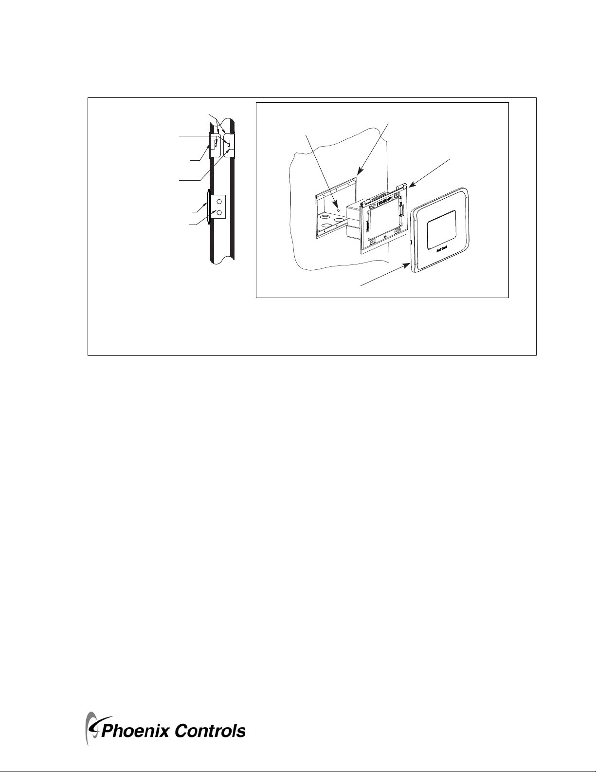
• Install in a triple gang-double deep electrical box (RACO 697, Appleton M3-350 or equivalent).
• Secure the triple gang-double deep electrical box to the stud(s) by using the mounting hole in the side of
the electrical box (see figure below for mounting hole location). Drive the mounting screws from the inside
of the electrical box into the wall studs to prevent sharp objects from protruding into the electrical box.
• Ensure the mounting is level and flush to the wallboard surface.
2
MKT-0262 MPC-1748 Rev 02/13
Page 7
APM2 Rough-In Installation Guide
Single Gang
Electrical Box
1/4" x .170 Tube Barb
(Conduit between
sensors and monitor
panel may be required.)
Reference
Pressure Pickup
Room
Pressure Pickup
APM2
NOTE: Connecting tubing and electrical
boxes are field-supplied.
Triple Gang Double Deep
Electrical Box
WALL MOUNT DIMENSIONS
Triple gang double deep electrical box—5.625" (220 mm) W x 3.5" (114.3 mm) H x 3.5" (63.5 mm) D
Single gang electrical box—2" (51 mm) W x 3" (76 mm) H x 3.5" (63.5 mm) D*
* Dimensions are approximate.
Advanced Pressure Monitor II Rough-In Installation
Installation Overview
Electrical Box
Mounting Hole
Figure 1-1. Wall Mount Installation Overview
1.3.1 Wiring Recommendations
APM2 Faceplate
Rough-in Electrical Box
- Raco 697
- Appleton M3-350
APM2
• All circuits must conform to the requirements of an NEC Class 2 (dry) circuit.
• Use multiple transformers instead of larger transformers when more than 100 VA is required.
• Each pressurization zone should have either a dedicated single-phase primary circuit, or a secondary circuit
disconnect.
•Refer to Phoenix Recommended Cables on page 33 for approved cable manufacturers and wire types.
• Use stranded wire for ease of installation.
• Follow good wiring practices:
• Locate cables away from sources of electrical interference (EMI/RFI).
• Do not run signal or communication cable in the same conduit or wire way as power cables.
• If signal cable must cross power cables place these at a 90-degree angle.
• Shield or drain wires, if required, should be wrapped with insulating tape to prevent contact with exposed
conductors or contacts.
• Maintain a consistent color code or polarity all the way through the wiring system.
• Power supply and signal isolation on I/O devices vary from manufacturer to manufacturer. Verify the
wiring device manufacturer’s recommendations for isolating power and signal common connections and
maintain polarity.
• Local and national electrical codes take precedence.
3
MKT-0262 MPC-1748 Rev 02/13
Page 8
Advanced Pressure Monitor II Rough-In Installation
Installation Overview
• Strip 0.25" (6.4 mm) of insulation from each conductor, twist the strands, insert the conductor fully into
the terminal block, and tighten the terminal.
•Test the wire connection by pulling on each conductor.
WARNING: Wiring must be performed by a licensed electrician according to local and state codes.
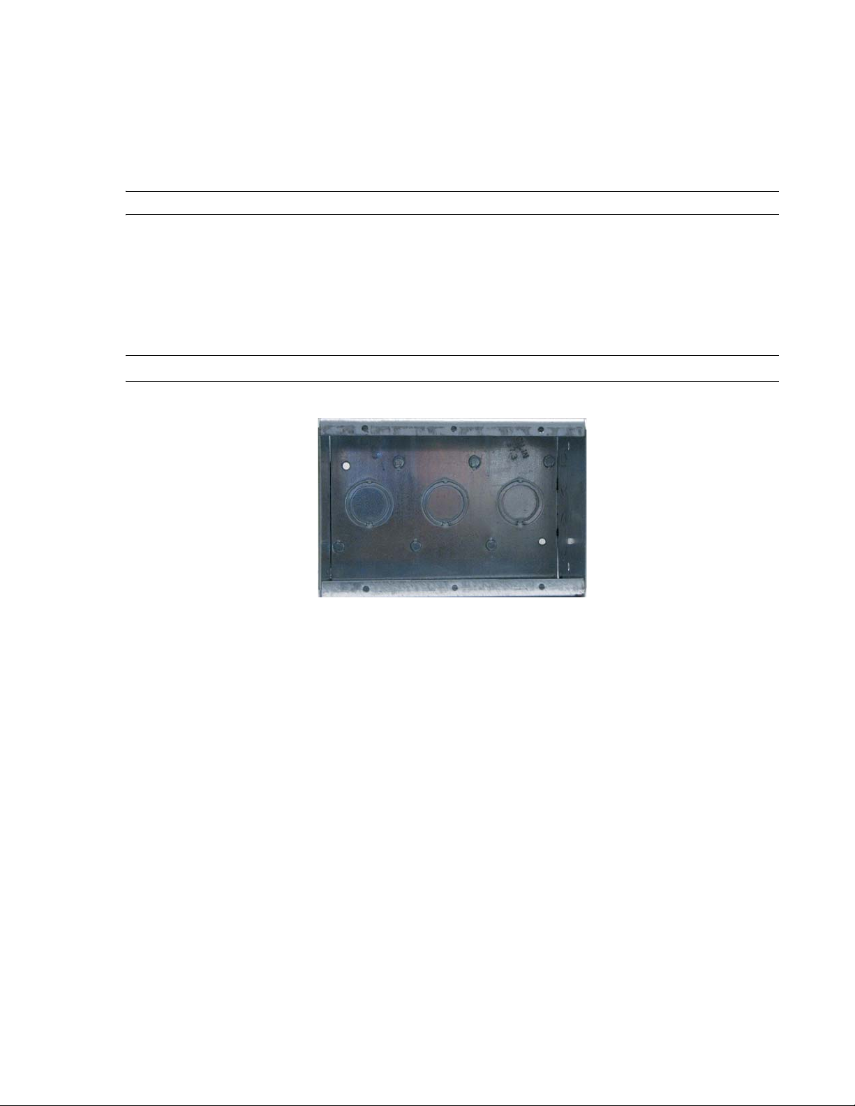
1.3.2 Wiring Triple Gang Electrical Box
USE ONLY THE KNOCKOUTS ON THE TOP OR BOTTOM AT THE BACK OF THE ROUGH-IN
ELECTRICAL BOX. The front knockouts will be inaccessible once the APM2 is installed. Strain relief and seal
box as required.
NOTE: Install power and signal wires into separate knockouts to avoid noise.
Figure 1-2. Wiring in the Triple Gang Electrical Box
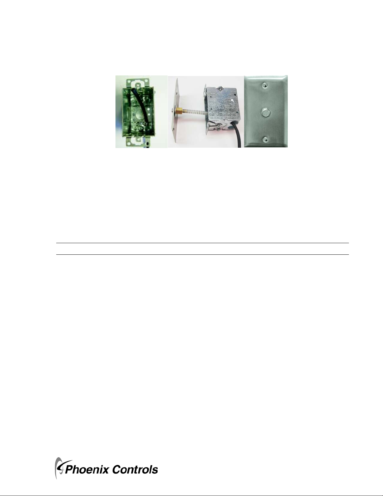
1.3.3 Plumbing Rough-In
If the internal pressure sensor will be used, then typically a Pressure Pickup Port is installed in the monitored
room and another one is installed in the reference area (typically a hallway). 0.25" nylon tubing is typically used
to bring the pressure signal from this point of measurement to the pressure inputs on the back of the APM2.
Install a single gang electrical box anywhere inside the room, typically high on the wall in an inconspicuous area.
This will be used for the room pressure signal (room monitor pressure port labeled HIGH). Run 0.25" tubing
from this electrical box to the triple gang box that the pressure monitor will be mounted to in the finish stage
of the installation.
CAUTION: Be careful in running the tubing in a way that the tube is protected from being damaged by being cut
or penetrated by screws or nails or being crimped so that the pressure signal integrity is affected. Do
not tighten strain reliefs so that they crimp the tubing. Tape the open ends of the tubes closed to
prevent contamination of the inside of the tubing.
Install a second single gang box on the corridor, ante room or other reference pressure area. This will be used
for the low pressure side or reference side pressure signal. This will be run to the triple gang box and connected
to the APM2 pressure port labeled LOW.
4
MKT-0262 MPC-1748 Rev 02/13
Page 9
APM2 Rough-In Installation Guide
Advanced Pressure Monitor II Rough-In Installation
Installation Overview
If an external sensor will be used then run the pressure signals (room and reference) to the remote transducer.
Figure 1-3. Pressure Pickup Port Installation
1.3.4 Use of External Transducers
The APM2 has the option to use the internal pressure sensor or external pressure transducers (ordered
separately). If external pressure sensors are being used then no tubing needs to be run into the electrical box.
Instead the remote pressure transducer will be separately mounted, plumbed and wired. Only the wire for the
analog output of that transducer(s) will be run to the APM2. If two rooms are being monitored, you have the
choice to use the internal pressure sensor and an external (remote) transducer for the second room, or two
external remote transducers may be used and wired to the analog inputs in the back of the unit.
NOTE: See Phoenix Recommended Cables on page 33 for approved cable manufacturers and wire types.
Layout the system in terms of wiring:
• Power: 24 Vac, 9 VA
• Annunciator/relay: remote alarm wiring if being used
• Analog output: 0-5 or 0-10 Vdc or 4-20 mA.
• Analog Input wiring: there are two analog inputs that can be used to bring signals from remote pressure
transducers
• Digital Input: the digital input can be used as a door status indication, these would be wired to a door switch
mounted in the door jamb.
Once the installation has been planned, locate and mount the electrical box and bring all tubing, power, earth
ground, analog input, digital input, relay/annunciator, analog output communications wiring into the triple
gang box.
MKT-0262 MPC-1748 Rev 02/13
5
Page 10
Advanced Pressure Monitor II Rough-In Installation
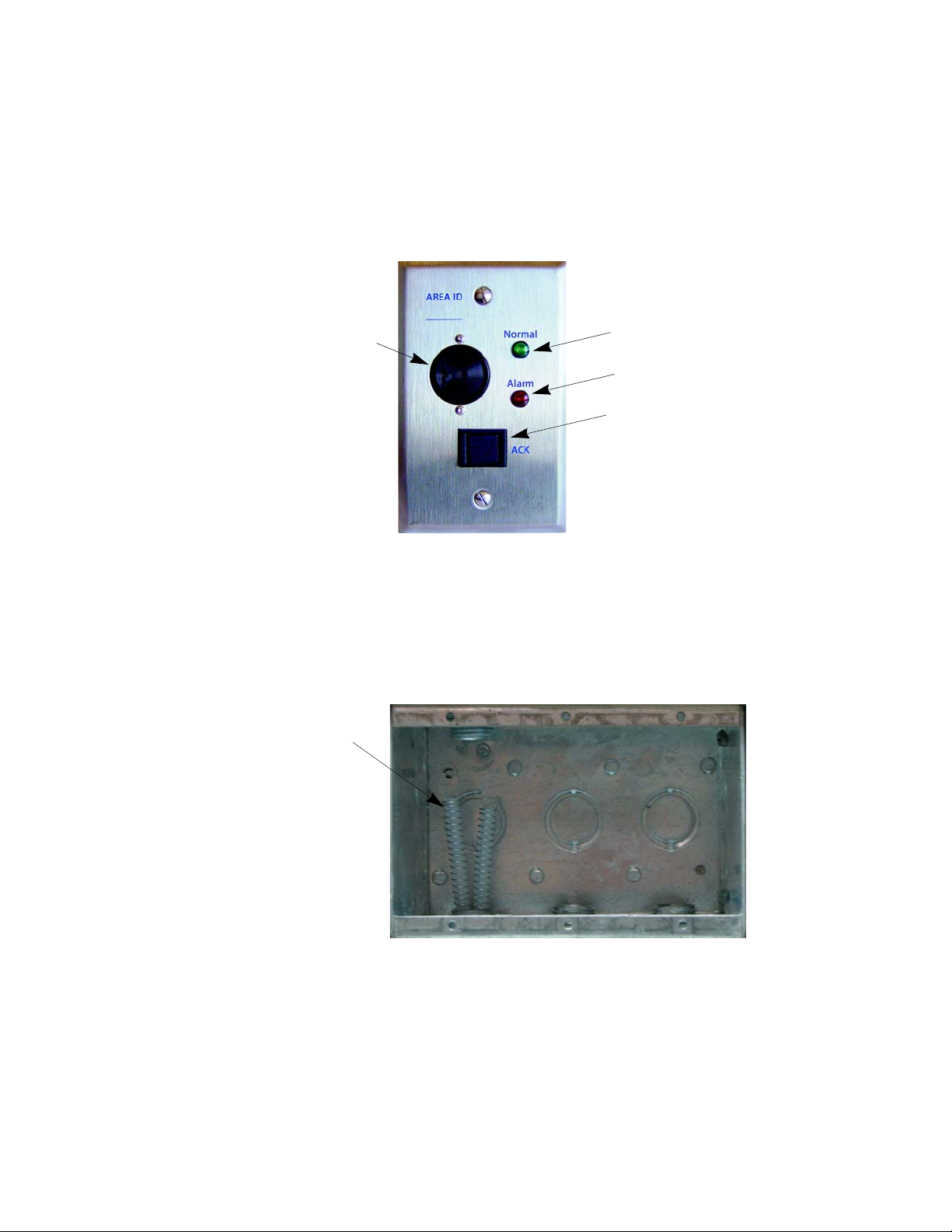
Green LED
Red LED
Acknowledge
Switch
Audible
Alarm
Soft Silicon
Tubing with
Integrated
Springs
Plumbing (Finish)
1.3.5 Remote Annunicator
If an remote annunciator will be used, then mount a single gang electrical box in the desired location and run
wires to it.
Figure 1-4. Remote Annunciator
1.4 Plumbing (Finish)
Use the following procedure for all room types positive, negative or neutral.
The biggest problem that can occur during plumbing is kinking of the often stiff nylon 0.25" tubing that is used
for running pressure signals from the APM2 to the monitored spaces. To prevent buckling and collapse of this
stiff tubing inside the electrical box, use the supplied soft silicone tubing with integrated springs and tubing
adapters to transition from the field tubing to the pressure fittings on the APM2.
6
MKT-0262 MPC-1748 Rev 02/13
Page 11
Advanced Pressure Monitor II Rough-In Installation
Wiring
Attach pressure tubing as follows:
1. Install the supplied silicone tube (with integrated spring) and attached barbed tube adaptor onto the end of
the 0.25 field tubing. Thread the tubes, with installed adaptor, through the conduit opening at the bottom
of the electrical box.
2. Next push the open end of the soft silicone tubing onto the APM2 pressure tube port labeled "HIGH".
3. For the most pressure stable operation, a Pressure Pickup Port installed in the reference pressure area is also
recommended. In this case, install the Pressure Pickup Port in a hallway or reference space.
4. Next push the open end of the soft silicone tubing onto the APM2 pressure tube port labeled "LOW".
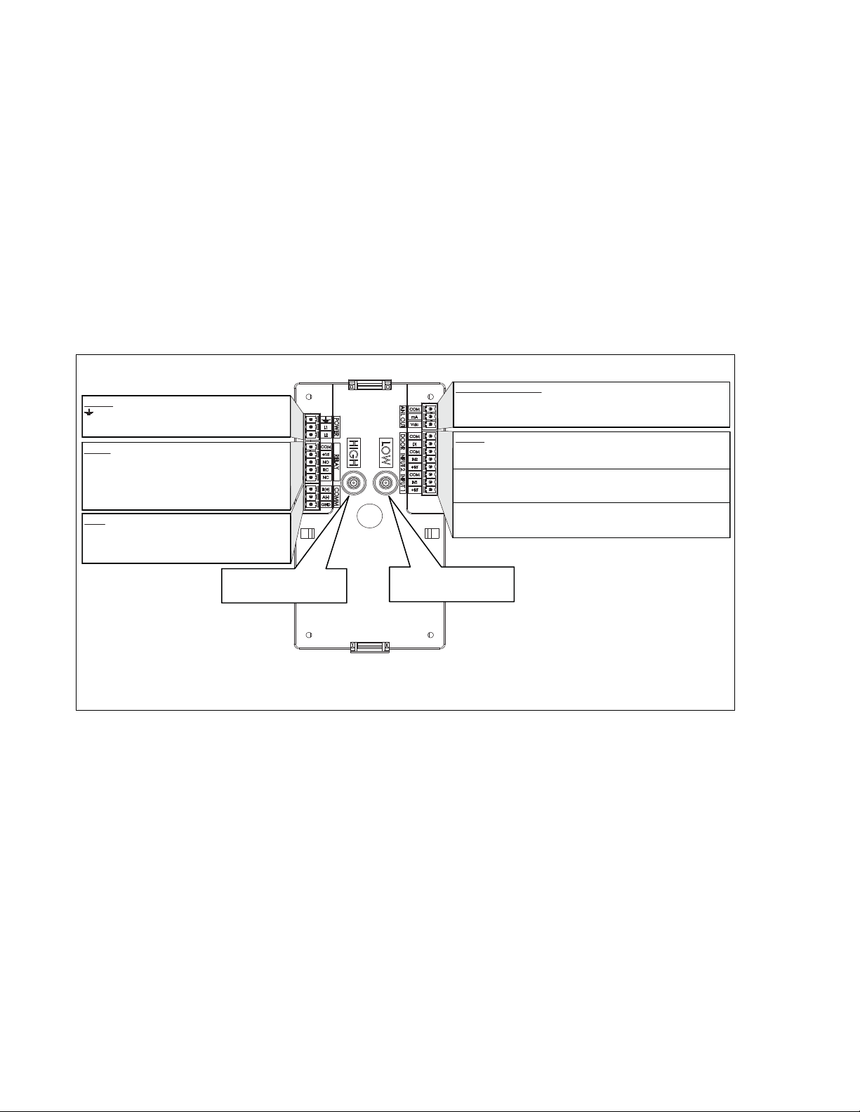
1.5 Wiring
ANALOG (ANL) OUTPUT
POWER
L1 24 Vac
L2 24 Vac
RELAY
COM COM
+15 +15 Vdc
NO Normally Open
RC Relay COM
NC Normally Closed
COM BACnet APM2-xx-ENG-BAC Products
B (+)
A (-)
GND
Earth Ground
THIS PAGE INTENTIONALLY LEFT BLANK.
COM COM
mA Current Output (4-20 mA)
Vdc Voltage Output (0-5 Vdc, 0-10 Vdc)
INPUTS (wired to door N.O. contact)
COM COM Door
DI Digital Input
COM COM Analog Input2
IN2 Analog Input2 (0-5, 0-10Vdc)
+15 15 Vdc
COM COM Analog Input1
IN1 Analog Input1 (0-5, 0-10Vdc)
+15 15 Vdc
HIGH or room pressure tubing
contacts here
REAR VIEW
LOW or re ference pressure tubing
connects here
Figure 1-5. Rear View of the APM2 (BACnet) Showing Wiring and Plumbing Connections
MKT-0262 MPC-1748 Rev 02/13
7
Page 12
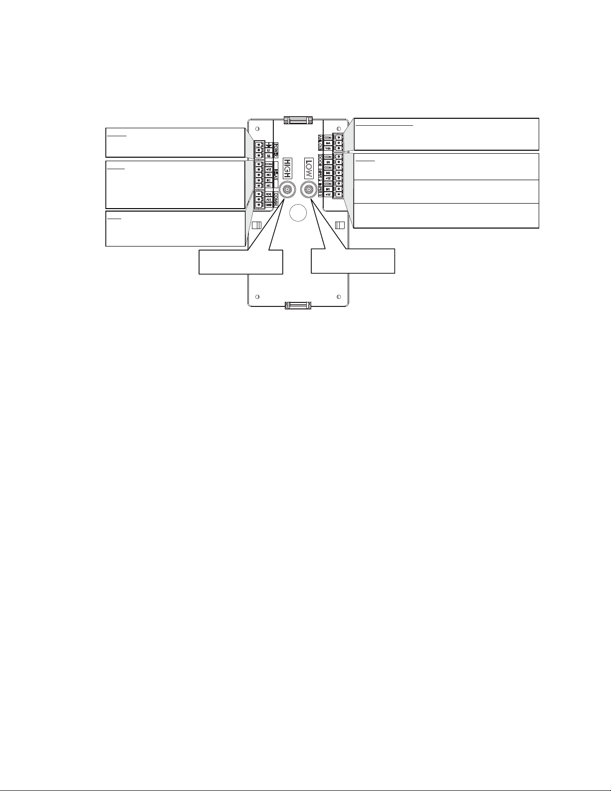
Advanced Pressure Monitor II Rough-In Installation
ANALOG (ANL) OUTPUT
COM COM
mA Current Output (4-20 mA)
Vdc Voltage Output (0-5 Vdc, 0-10 Vdc)
INPUTS (wired to door N.O. contact)
COM COM Door
DI Digital Input
COM COM Analog Input2
IN2 Analog Input2 (0-5, 0-10Vdc)
+15 15 Vdc
COM COM Analog Input1
IN1 Analog Input1 (0-5, 0-10Vdc)
+15 15 Vdc
Earth Ground
L1 24 Vac
L2 24 Vac
HIGH or room pressure tubing
connects here
LOW or re ference pressure tubing
connects here
POWER
RELAY
COM COM
+15 +15 Vdc
NO Normally Open
RC Relay COM
NC Normally Closed
COM NOT AVAILABLE
B (+)
A (-)
GND
REAR VIEW
Wiring
Figure 1-6. Rear View of the APM2 (Analog) Showing Wiring and Plumbing Connections
The back of the APM2 has electrical connectors labeled with their function. The mating electrical connectors
(supplied) are color coded and labeled with the matching function.
1.5.1 Power, Labeled POWER, L1, L2, Ground Symbol
Starting with the 3 pin Power connector:
1. Connect the 24 Vac lines to L1 and L2.
2. Connect a ground wire, GND, from the ground lug to the GND on the connector.
3. Install Connector.
The APM2 operates at 18-32 Vac, 50/60 Hz and consumes 2.6 W nominal, 9.6 W max.
1.5.2 Analog Output, Labeled ANL OUT
If using the analog output and want Voltage output, connect to the terminals labeled VDC and COM.
If using the analog out and want a 4-20 mA signal, connect to terminals labeled mA and COM. Connect this
output to the BMS system or other monitoring device.
8
MKT-0262 MPC-1748 Rev 02/13
Page 13

APM2 Rough-In Installation Guide
+
-
+ 15 Vdc
IN1
COM
APM2
Setra Model 264
Current Output
249
Ohm
Advanced Pressure Monitor II Rough-In Installation
Wiring
1.5.3 Analog Input, Labeled DOOR, INPUT2, INPUT1
There are two analog inputs available for remotely mounted transducer inputs. These are INPUT1 and
INPUT2.
A 15 Vdc (14.8 to 15.2) excitation is available to power up to two transducers. They can source 90 mA max.
combined. It is labeled as +15 on the connectors.
If using this to power a remote transducer, connect this to the positive excitation terminal of the transducer.
1.5.3.1 Measuring Analog Inputs
There are three potential analog inputs that can be measured, 0-5, 0-10 and 4-20 mA.
• For 0-5 or 0-10 Vdc inputs connect the positive (+) output of the transducer to terminal labeled IN1, connect the common output of the transducer to the terminal labeled COM.
• For 4-20 mA loops install a 250 ohm resistor between the terminals labeled In1 or IN2 (whichever input
you’re going to) and COM. The monitor will be measuring the voltage across this resistor as 1-5 Vdc corresponding to 4-20 mA.
If you will be monitoring the status of a door position, then wire the contacts labeled DOOR to the normally
open contacts on a door jamb switch. The monitor will show the door "Warning" (when enabled) when the
door is open. The door jamb switch should be closed when the door is closed and open when the door is open.
1.5.4 Optional Remote Transducer Wiring
The figure below references the Setra remote sensors equipped with 4-20 mA output. The instruction booklets
supplied with the sensors cover both the
3-wire voltage output configuration and 2-wire current configuration. The figure below clarifies the 2-wire 420 mA connection between the Setra 264 or 267 and APM2 inputs. The same connection applies to IN2 (AI2).
If the APM2 output is configured for 4-20 mA on the AO, the users can use either 249 or 500 Ohm resistors
depending on whether they desire 1-5 or 2-10 Vdc.
Figure 1-7. Optional Remote Transducer Wiring
9
MKT-0262 MPC-1748 Rev 02/13
Page 14
Advanced Pressure Monitor II Rough-In Installation
Wiring
1.5.5 Relay and Annunciator Output, Labeled RELAY
There is an SPDT dry contact available. When an alarm occurs the Normally Open (NO) and the Common
(COM) internal contacts will be closed. During no alarm conditions the Normally Closed (NC) and COM are
shorted.
This relay can also drive a Remote Annunciator.
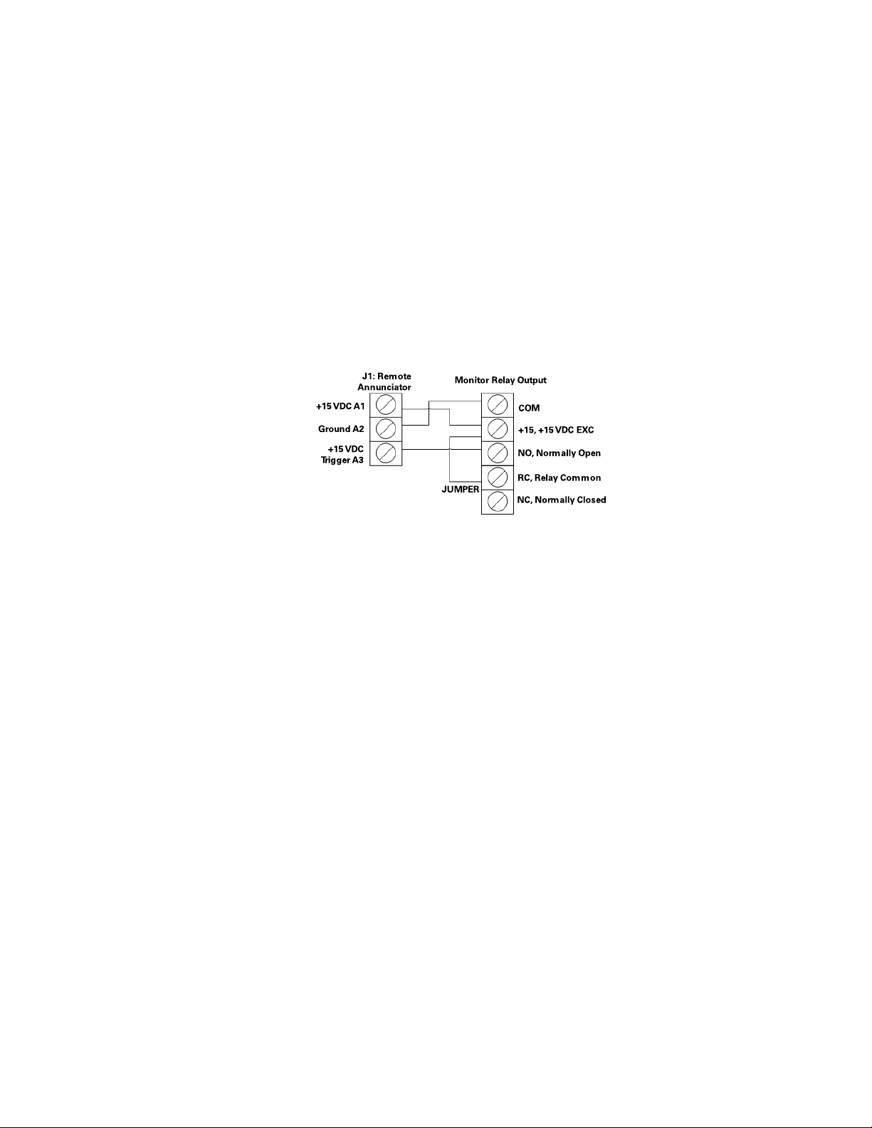
1.5.6 Optional Remote Annunciator Wiring
In the figure below, the Remote Annunciator connector is at left, and the APM2 connector is at right.
Figure 1-8. Remote Annunciator Wiring Diagram
• To connect +15 Vdc power, connect the +15 Vdc from the relay connector to +15 Vdc, A1 at the Remote
Annunciator. This supplies 15 V exc. to the Remote Annunciator for powering the circuit during normal
conditions.
• To connect power return, connect the COM of relay connector to Ground, A2 at the Remote Annunciator.
• On of the relay connector, connect a short jumper between the +15 and relay connector. This will connect
the internal 15V supply to the common of the internal alarm relay.
• Connect the NO on the relay output to the +15 Vdc Trigger, A3 terminal on the Remote Annunciator.
When an alarm occurs and after the programmed alarm delay times out, the internal relay will supply 15 V to
the Remote Annunciator circuit to actuate the audible buzzer and the red LED.
10
MKT-0262 MPC-1748 Rev 02/13
Page 15

APM2 Rough-In Installation Guide
Advanced Pressure Monitor II Rough-In Installation
1.5.7 Third Party Remote Annunciator
The APM2 can drive other annunciators that are powered by a 15V supply, 50 mA max current draw, and
accept a 15V trigger. If purchased separately, the Remote Annunciator can also be driven as shown below.
Figure 1-9. 3rd Party Remote Annunciator Wiring Diagram
1.5.8 Completing the Finish Wiring
1. Connect all the electrical connectors matching the wiring connector with the mates on the back of the
unit. Connectors are color coded and keyed.
2. Connect the pressure signals to the HIGH and LOW ports on the back of the unit. The springs on the
outside of the tubing are there to prevent buckling of the tube. As you push the unit into the electrical box
push the black instrument tubing into the conduit tube or into the wall, Ideally the supplied silicone tube
is the only tubing in the electrical box after the unit is slid in as far as it will go.
Wiring
Figure 1-10. Connecting Electrical Connectors to Back of APM2
3. Mount the unit cover to the electrical box using four of the supplied mounting screws. Leaving screws
slightly loose adjust the cover so that it is square. Securely tighten so that the back of the cover is tight to
the finish wall surface.
MKT-0262 MPC-1748 Rev 02/13
11
Page 16

Advanced Pressure Monitor II Rough-In Installation
Wiring
Figure 1-11. Mounting APM2 in Triple Gang Electrical Box
4. Mount the front cover assembly.
Figure 1-12. Installed APM2
12
MKT-0262 MPC-1748 Rev 02/13
Page 17

APM2 Rough-In Installation Guide
Fitting an APM2 in an APM100 Enclosure
Overview
Section 2. Fitting an APM2 in an APM100 Enclosure
2.1 Overview
APM100 pressure monitors from Phoenix Controls can be replaced in the field using the newer APM2 units.
However, it is important to order the Retrofit Kit version of the APM2 product for compatibility with the
existing enclosure. The APM2 Retrofit Kit includes additional parts and modifications to the standard APM2
product that permits easy installation in the field.
These instructions outline how to replace an APM100 series pressure monitor with APM200 series units.
APM100 models installed in the field are housed in a 5-gang single-deep electrical box. The APM2 models
require a 3-gang double-deep electrical box for new installations, so it will not fit directly into the APM1
enclosure without this adapter kit.
2.1.1 What Is Included In Your Kit
• APM2 model with the pressure range you ordered with 90 degree pressure taps on the rear of the unit for
proper seating in the APM100 enclosure
• Stainless steel adapter plate to cover the larger APM100 wall opening
• Four (4) phillips head screws to secure APM2 to the adapter plate
• Four (4) Allen head screws to secure adapter plate to the existing APM100 enclosure
• APM2 white faceplate
• APM2 installation instructions
• APM2 connector kit
• APM2 calibration certificate
2.1.1.1 Not Included - Tools You Will Need
• Small blade terminal screwdriver
• Phillips head screwdriver
• 1/8" Allen wrench
13
MKT-0262 MPC-1748 Rev 02/13
Page 18

Fitting an APM2 in an APM100 Enclosure
Instructions
2.2 Instructions
IMPORTANT: As part of the site preparation, any wiring or tubing coming into the APM100 unit may
need to be moved to accomodate the depth of the APM2.
Figure 2-1. APM100 Display
2.2.1 Turn Off Power To the APM100 Unit And Remove It From The Wall
1. Remove the four allen head screws from the APM100.
CAUTION: Carefully, pull the APM100 out of the APM100 box.
2. Disconnect power and all connectors. Label connectors so it will be clear how to reconnect them to the
APM2 unit.
3. Disconnect pressure tubing from the APM100 and label room side and reference side tubing.
14
MKT-0262 MPC-1748 Rev 02/13
Page 19

APM2 Rough-In Installation Guide
Four phillips head
screws provided
Fitting an APM2 in an APM100 Enclosure
Instructions
2.2.2 Ensure Existing APM1 Enclosure Is Prepared For APM2 Unit
1. Make sure the wall surface around the existing enclosure is flat and clean with no wall damage or holes
beyond the electrical box.
2. A full 5.18" of the center of the existing enclosure will be occupied by the APM2 unit when it is installed.
Any wires or tubing in this region of the electrical box should be moved to the outer perimeter of the
enclosure so the APM2 can slide in without obstructions. You may need to use the knockouts on either
sides, tops or bottom as shown below.
Figure 2-2. APM100 Knockout Locations
2.2.3 Attach the Base APM2 Unit
Mount the base APM2 unit to the adapter plate using the four supplied phillips head screws. Leaving screws
slightly loose adjust the cover so that it is square. Securely tighten so that the back of the cover is tight to the
finish wall surface.
Figure 2-3. Installing APM2 to the Adapter Plate
15
MKT-0262 MPC-1748 Rev 02/13
Page 20

Fitting an APM2 in an APM100 Enclosure
Instructions
2.2.4 Wiring
POWER
L1 24 Vac
L2 24 Vac
RELAY
COM COM
+15 +15 Vdc
NO Normally Open
RC Relay COM
NC Normally Closed
COM BACnet APM2-xx-ENG-BAC Products
B (+)
A (-)
GND
Earth Ground
ANALOG (ANL) OUTPUT
COM COM
mA Current Output (4-20 mA)
Vdc Voltage Output (0-5 Vdc, 0-10 Vdc)
INPUTS (wired to door N.O. contact)
COM COM Door
DI Digital Input
COM COM Analog Input2
IN2 Analog Input2 (0-5, 0-10Vdc)
+15 15 Vdc
COM COM Analog Input1
IN1 Analog Input1 (0-5, 0-10Vdc)
+15 15 Vdc
HIGH or room pressure tubing
contacts here
REAR VIEW
LOW or re ference pressure tubing
connects here
Figure 2-4. Rear View of the APM2 Showing Wiring and Plumbing Connections
The back of the APM2 has electrical connectors labeled with their function. The mating electrical connectors
(supplied) are color coded and labeled with the matching function.
Refer to the Advanced Pressure Monitor II User’s Guide (MKT-0263) for detailed wiring instructions.
2.2.5 Remotely Switching Alarm Setpoints
The APM100 model uses dry contacts to switch pressure setpoints between positive and negative, whereas the
APM2 uses an input voltage: 0, 5 or 10 Volts to switch pressure setpoints between negative-neutral-positive
respectively. If this function was used on the APM100 product, adaptations will need to be made to restore their
function with other equipment or devices that will generate the 0, 5 or 10 Volt signal.
16
MKT-0262 MPC-1748 Rev 02/13
Page 21

APM2 Rough-In Installation Guide
1/8" Allen head
screws supplied
Fitting an APM2 in an APM100 Enclosure
Instructions
2.2.6 Modified Pressure Taps
The APM2 retrofit unit differs from the standard APM100 product. The rear of the unit uses 90º pressure taps
instead of straight-through pressure taps. This allows the unit to be installed in the shallower APM100 box. The
shallower APM100 box permits enough space for existing pressure tubes in the back to be connected.
Figure 2-5. APM2 Retrofit Kit Pressure Taps
2.2.7 Complete the Installation
1. Complete the installation following the instructions in the Advanced Pressure Monitor II User’s Guide
(MKT-0263), which can be obtained from the Partner Login area of http://www.phoenixcontrols.com/.
2. Once wiring and pressure tubes are connected, verify functionality of the APM2 before sliding it into the
wall enclosure.
3. Install the adapter plate to the wall enclosure by using the four 1/8" Allen head screws supplied.
Figure 2-6. Installing Adapter Plate to APM100 Box
17
MKT-0262 MPC-1748 Rev 02/13
Page 22

Fitting an APM2 in an APM100 Enclosure
Instructions
4. Mount the front cover assembly.
Figure 2-7. Installed APM2
18
MKT-0262 MPC-1748 Rev 02/13
Page 23

APM2 Rough-In Installation Guide
APM2 Central Display Rough-In Installation
Required Parts to be Supplied by the Installer
Section 3. APM2 Central Display Rough-In Installation
For the APM2 Central Display to be installed correctly, the rough-in phase of the project must be completed
properly. This section will outline the specific considerations the General Contractor must pay attention to so
that the final wiring and commissioning will go smoothly.
During rough-in installation, the field wiring can be run in the walls and routed between the triple gang
electrical box, the Building Management System (BMS), power supply, earth ground and so on.
3.1 Required Parts to be Supplied by the Installer
The following is a list of parts required and supplied by the installer for the APM2 Central Display:
• Triple gang-double deep electrical box (RACO 697 or Appleton M3-350), quantity 1
• Green grounding screw, quantity 1
• Power (18 AWG recommended) and signal wiring (22 AWG recommended), as needed. Refer to Phoenix
Recommended Cables on page 33.
• EMT conduit (if required by local code)
•24 Vac Transformer
3.2 Parts included with Your Order
The following are parts that are included in your order:
• APM2 Central Display, quantity 1
• APM2 Faceplate, quantity 1
• Mounting screws, 6-32 x 1/2 Phillips head, quantity 5
• Mating Electrical Connectors, Phoenix Contact MC plug kit, 2 green connectors
3.3 Installation Overview
• Install in a triple gang-double deep electrical box (RACO 697, Appleton M3-350 or equivalent).
• Secure the triple gang-double deep electrical box to the stud(s) by using the mounting hole in the side of
the electrical box (see figure below for mounting hole location). Drive the mounting screws from the inside
of the electrical box into the wall studs to prevent sharp objects from protruding into the electrical box.
• Ensure the mounting is level and flush to the wallboard surface.
19
MKT-0262 MPC-1748 Rev 02/13
Page 24

APM2 Central Display Rough-In Installation
Faceplate
Main Unit
Rough-in Electrical Box
- Raco 697
- Appleton M3-350
Electrical Box
Mounting Hole
WALL MOUNT DIMENSIONS
Triple gang double deep electrical box—5.625" (142.9 mm) W x 3.5" (88.9 mm) H x 3.5" (88.9 mm) D
* Dimensions are approximate.
Installation Overview
Figure 3-1. Wall Mount Installation Overview
3.3.1 Wiring Recommendations
• All circuits must conform to the requirements of an NEC Class 2 (dry) circuit.
• Use multiple transformers instead of larger transformers when more than 100 VA is required.
• Each pressurization zone should have either a dedicated single-phase primary circuit, or a secondary circuit
disconnect.
•See Phoenix Recommended Cables on page 33 for approved cable manufacturers and wire types.
• Use stranded wire for ease of installation.
• Follow good wiring practices:
• Locate cables away from sources of electrical interference (EMI/RFI).
• Do not run signal or communication cable in the same conduit or wire way as power cables.
• If signal cable must cross power cables place these at a 90-degree angle.
• Shield or drain wires, if required, should be wrapped with insulating tape to prevent contact with exposed
conductors or contacts.
• Maintain a consistent color code or polarity all the way through the wiring system.
• Power supply and signal isolation on I/O devices vary from manufacturer to manufacturer. Verify the
• Local and national electrical codes take precedence.
wiring device manufacturer’s recommendations for isolating power and signal common connections and
maintain polarity.
20
MKT-0262 MPC-1748 Rev 02/13
Page 25

APM2 Rough-In Installation Guide
APM2 Central Display Rough-In Installation
Installation Overview
• Strip 0.25" (6.4 mm) of insulation from each conductor, twist the strands, insert the conductor fully into
the terminal block, and tighten the terminal.
•Test the wire connection by pulling on each conductor.
WARNING: Wiring must be performed by a licensed electrician according to local and state codes.
3.3.2 Wiring Triple Gang Electrical Box
USE ONLY THE KNOCKOUTS ON THE TOP OR BOTTOM AT THE BACK OF THE ROUGH-IN
ELECTRICAL BOX. The front knockouts will be inaccessible once the APM2 is installed. Strain relief and seal
box as required.
NOTE: Install power and signal wires into separate knockouts to avoid noise.
Figure 3-2. Wiring in the Triple Gang Electrical Box
21
MKT-0262 MPC-1748 Rev 02/13
Page 26

APM2 Central Display Rough-In Installation
Earth Ground
L1 24 Vac
L2 24 Vac
POWER
COMM
B (+)
A (-)
GND
REAR VIEW
BACnet Communications
(See Detail A)
DATA +
DATA -
COMM
B (+)
GND
A (-)
DETAIL "A"
GROUND SHIELD - ONE END ONLY
Wiring
3.4 Wiring
Figure 3-3. Rear View of the APM2 Central Display Showing Wiring Connections
The back of the APM2 Central Display has electrical connectors labeled with their function. The mating
electrical connectors (supplied) are color coded and labeled with the matching function.
3.4.1 Power, Labeled POWER, L1, L2, Ground Symbol
Starting with the 3 pin Power connector:
1. Connect the 24 Vac lines to L1 and L2.
2. Connect a ground wire, GND, from the ground lug to the GND on the connector.
3. Install Connector.
The APM2 operates at 18-32 Vac, 50/60 Hz and consumes 2.6 W nominal, 9.6 W max.
22
MKT-0262 MPC-1748 Rev 02/13
Page 27

APM2 Rough-In Installation Guide
APM2 Central Display Rough-In Installation
3.4.2 Completing the Finish Wiring
1. Connect all the electrical connectors matching the wiring connector with the mates on the back of the
unit. Connectors are color coded and keyed.
2. Mount the unit cover to the electrical box using four of the supplied mounting screws. Leaving screws
slightly loose adjust the cover so that it is square. Securely tighten so that the back of the cover is tight to
the finish wall surface.
Wiring
Figure 3-4. Mounting APM2 Central Display in Triple Gang Electrical Box
3. Mount the front cover assembly.
Figure 3-5. Installed APM2 Central Display
23
MKT-0262 MPC-1748 Rev 02/13
Page 28

APM2 Central Display Rough-In Installation
Wiring
THIS PAGE INTENTIONALLY LEFT BLANK.
MKT-0262 MPC-1748 Rev 02/13
24
Page 29

APM2 Rough-In Installation Guide
Ancillary Product Specifications
Model 264 Pressure Transducer
Section 4. Ancillary Product Specifications
NOTE: The following specifications are subject to changes without notice.
4.1 Model 264 Pressure Transducer
Table 1. Model 264 Pressure Transducer (Remote Transducer 0-5 V Output)
Model 264 Pressure Transducer
Performance Data
Standard Optional
1
Accuracy
Non-linearity (BFSL) ± 0.96 % FS ± 0.38 % FS ± 0.22 % FS
Hysteresis 0.10% FS 0.10% FS 0.10% FS
RSS (at constant temperature)
± 1.0 % FS ± 0.4 % FS ± 0.25 % FS
Non-repeatability 0.05% FS 0.05% FS 0.05% FS
3
°F (°C)
°F (°C)
2
0 - 150 (-18 - 65)
°F (°C)
0.033 (0.06)
To 0.5" WC 0.60
To 1.0" WC 0.50
0 - +175 (-18 - +79)
-65 - +250 (-54 - +121)
Thermal Effects
Compensated Range °F (°C)
Zero/Span Shift % FS/
Maximum Line Pressure 10 psi
Overpressure Up to 10 psi (range dependent)
Long-term Stability 0.5% FS / year
Position Effect Range Zero Offset (% FS/G)
Unit is factory calibrated at 0g effect in the
vertical position
Environmental Data
Temperature
Operating
Storage
Physical Description
Case Fire-retardant glass filled polyster (UL94 V-0 Approved)
Dimensions 2.75" (69.85 mm) W x 5.062" (128.57 mm)H x 2.40" (61.07 mm) D
Mounting
Electrical Connection Screw type terminal strip
Four screw holes on removable zinc-plated steel base (designed for 2.75"
snap track)
MKT-0262 MPC-1748 Rev 02/13
25
Page 30

Ancillary Product Specifications
Model 264 Pressure Transducer
Pressure Fittings 3/16" OD barbed brass pressure fitting for 1/4" push-on tubing
Zero and Span Adjustments Accessible on top of case
Weight (approximate) 10 ounces
Pressure Media
Typically air or similar non-conducting gases
Electrical Data—Voltage
Circuit 3-wire (Com, Exc, Out)
Excitation 9 - 30 Vdc
4
Output
Bi-directional output at zero pressure
Output impedance 100Ω
Electrical Data—Current
Circuit 2-wire
7
Output
Bi-directional output at zero pressure
0 - 5 Vdc
2.5 Vdc
4 - 20 mA
12 mA
5
6
8
9
Minimum supply voltage (Vdc) 9+0.02 x (resistance of receiver plus line)
Maximum supply voltage (Vdc) 30+0.004 x (resistance of receiver plus line)
1
RSS of non-linearity, hystereis and non-repeatability.
2
Units calibrated at nominal 70 °F. Maximum thermal error computed from this datum.
3
Operating temperature limits of the electronics only. Pressure media temperatures may be considerably higher.
4
Calibrated into a 50KΩ load, operable into a 5KΩ load or greater.
5
Zero output factory set to within ± 50 mV (± 25 mV for optional accuracies).
6
Span (full scale) output factory set to within ± 50 mV (± 25 mV for optional accuracies).
7
Calibrated at factory with a 24 Vdc loop supply voltage and a 250Ω load.
8
Zero output factory set to within ± 0.16 mA (± 0.08 mA for optional accuracies).
9
Span (full scale) output factory set to within ± 0.16 mA (± 0.08 mA for optional accuracies).
26
MKT-0262 MPC-1748 Rev 02/13
Page 31

APM2 Rough-In Installation Guide
+
SPAN
+
ZERO
INSTALLATION WARNING!
2.750 in.
(69.85 mm)
5.062 in.
(128.57 mm)
4.562 in.
(115.87 mm)
R0.078 in.
(R1.98 mm)
1.624 in.
(41.25 mm)
0.594 in.
(15.08 mm)
1.811 in.
(45.99 mm)
1.187 in.
(30.15 mm)
TYP.
TYP.
TYP.
1.662 in.
(42.21 mm)
0.312 in.
(7.92 mm)
0.385 in.
(9.78 mm)
TYP.
LOW
Model 264
HIGH
Serial Number:
Part Number:
Range:
Excitation:
Output:
Date Code: 3599
0-5 VDC
9-30 Vdc
0-5.0" WC
1015990
2641005WD2DT1C
COM
EXC OUT
PRESSURE PORTS
TOP VIEW
SIDE VIEW
#6 SCREW
WIRE CLAMP
3 PLACES
Ancillary Product Specifications
Model 264 Pressure Transducer
Figure 4-1. Model 264 Pressure Transducer
27
MKT-0262 MPC-1748 Rev 02/13
Page 32

Ancillary Product Specifications
Model 267 Pressure Transducer
4.2 Model 267 Pressure Transducer
Table 2. Model 267 Pressure Transducer
Performance Data
Standard Optional
1
Accuracy
Non-linearity (BFSL) ± 0.98 % FS ± 0.38 % FS ± 0.22 % FS
Hysteresis 0.10% FS 0.10% FS 0.10% FS
Non-repeatability 0.05% FS 0.05% FS 0.05% FS
RSS (at constant temperature)
Thermal Effects
2
± 1.0 % FS ± 0.4 % FS ± 0.25 % FS
Compensated Range °F (°C)
Zero/Span Shift % FS/
Maximum Line Pressure 10 psi
Overpressure Up to 10 psi (range dependent)
Warm-up Shift ± 0.1% FS Total
Position Effect Range Zero Offset (% FS/G)
Unit is factory calibrated at 0g effect in the
vertical position
Environmental Data
Temperature
3
Operating
Storage
Physical Description
Case IP65/NEMA plastic-filled polycarbonate (UL94 V-0 Approved)
Dimensions 6.20" (158 mm) W x 2.68" (68 mm) H x 3.65" (93 mm) D
Electrical Connection Screw type terminal strip
°F (°C)
°F (°C)
°F (°C)
40 - 150 (5 - 65)
± 0.033 (± 0.06)
To 0.5" WC 0.60
To 1.0" WC 0.50
0 - +150 (-18 - +65)
+65 - +180 (-54 - +82)
PG-9/PG13.5 Strain relief, 1/2" conduit opening, or 9-pin D-sub connector
Electrical Termination
NOTE: 9-pin D-sub connector is not suitable for NEMA4/IP-65 environments
Pressure Fittings
Weight (approximate) 9 ounces (255 g)
Pressure Media
Typically air or similar non-conducting gases
3/16" O.D. barbed brass for 1/4" push-on tubing (Standard)
Static Pressure Probe (Optional)
1/4" NPTF brass (Optional)
28
MKT-0262 MPC-1748 Rev 02/13
Page 33

APM2 Rough-In Installation Guide
Electrical Data—Voltage
Circuit 3-wire (Exc, Gnd, Sig)
Excitation/Output
Excitation/Output
Bi-directional output at zero pressure Mid-range of specified output
Output impedance 100Ω
Re-ranging 5 position dip switches (inside case)
Electrical Data—Current
Circuit 2-wire protected from miswiring
6
Output
External Load 0 - 800Ω
Bi-directional output at zero pressure 12 mA
Minimum loop supply voltage (Vdc) 9 + 0.02 x (resistance of receiver plus line)
Maximum supply voltage (Vdc) 30 + 0.004 x (resistance of receiver plus line)
(0-5 Vdc output)
(0-10 Vdc output)
9 - 30 Vac / 12 - 40 Vdc
11 - 30 Vac / 13 - 40 Vdc
4 - 20 mA
7
Ancillary Product Specifications
Model 267 Pressure Transducer
Re-ranging 4 position dip switches (inside case)
1
RSS of non-linearity, hystereis and non-repeatability.
2
Units calibrated at nominal 70 °F. Maximum thermal error computed from this datum.
3
Operating temperature limits of the electronics only. Pressure media temperatures may be considerably higher or lower.
4
Calibrated into a 50K Ω load, operable into a 5K Ω load or greater.
5
Zero output factory set to within ± 50 mV (± 25 mV for optional accuracies).
Span (full scale) output factory set to within
6
Calibrated at factory with a 24 Vdc loop supply voltage and a 250 Ω load.
7
Zero output factory set to within ± 0.16 mA (± 0.08 mA for optional accuracies).
± 50 mV (± 25 mV for optional accuracies).
Span (full scale) output factory set to within ± 0.16 mA (± 0.08 mA for optional accuracies).
29
MKT-0262 MPC-1748 Rev 02/13
Page 34

Ancillary Product Specifications
Model 267 Pressure Transducer
2.68 in.
(68 mm)
1.34 in.
(34 mm)
6.10 in.
(155 mm)
5.60 in.
(142 mm)
0.18 in.
(Ø4.5 mm)
0.75 in.
(19 mm)
0.50 in.
(13 mm)
3/16" O.D. PRESSURE FITTING
FOR 1/4" PUSH-ON TUBING
1.73 in.
(44 mm)
0.93 in.
(24 mm)
Figure 4-2. Model 267 Pressure Transducer
0.80 in.
(20 mm)
Ø7/8 in.
(Ø22 mm)
1.18 in.
(30 mm)
1.29 in.
(33 mm)
2.36 in.
(60 mm)
30
MKT-0262 MPC-1748 Rev 02/13
Page 35

APM2 Rough-In Installation Guide
4.52 in.
(114.78 mm)
.20 in.
(5.08 mm)
2.77 in.
(70.23 mm)
.74 in.
(18.69 mm)
.43 in.
(10.80 mm)
2.68 in.
(68 mm)
1.97 in.
(50 mm)
4.3 Remote Annunciator
Table 3. Remote Annunciator
Enclosure 2.75" W x 4.5" H stainless steel wall cover plate
External Supply 15 Vdc, 50 mA maximum
Display Panel Green and red LED indicators and Acknowledge (ACK) switch
Audible Alarm 0-85 dBA measured 4" from annunciator
Acknowledge Switch Momentarily turns off audible alarm
Ancillary Product Specifications
Remote Annunciator
Figure 4-3. Remote Annunciator
31
MKT-0262 MPC-1748 Rev 02/13
Page 36

Ancillary Product Specifications
2.77 in.
(70.23 mm)
4.52 in.
(114.78 mm)
.20 in.
(5.08 mm)
.82 in.
(21 mm)
Pressure Pickup Port
4.4 Pressure Pickup Port
Table 4. Pressure Pickup Port
Cover Stainless steel standard wall cover plate
Mounting Standard single gang electrical box (2 screws included)
Dimensions 2.77" (70.23 mm) W x 4.52" (114.78 mm) H x 1.02" (26.08 mm) D
Pressure Fitting 1/4" flexible push-on tubing (Standard)
Figure 4-4. Pressure Pickup Port
32
MKT-0262 MPC-1748 Rev 02/13
Page 37

APM2 Rough-In Installation Guide
4.5 Phoenix Recommended Cables
Ancillary Product Specifications
Phoenix Recommended Cables
Cable
Ty p e
2C
Round
2C
Round
TP No FTT-10 (4500’)
TP Yes FTT-10 (4500’)
TSP No I/O signal
2 TSP No I/O signal
3C
Round
3C or
4C
Round
4C
Round
5C
Round
Plenum
Rated
No 24 Vac power to
Yes 24 Vac power to
No Signal 22 Belden 8443 1: Red
Yes Signal 22 Belden 88444 Windy City
No Signal 22 Belden 8444 Manhattan
No Signal 22 Belden 8445 Manhattan
Function
LOSEA or
Pneumatic (110’
max at load
24 Vac power to
HiSea (288’ max
1, 2
at load
LOSEA or
Pneumatic (110’
max at load
24 Vac power to
HiSea (288’ max
at load
TP1250 (425’)
FTT-10 (8800’) 16 Windy City
TP1250 (425’)
FTT-10 (8800’) 16 Windy City
wiring
wiring
)
1, 2
)
1
2
Wire
Gauge
18 Belden 9409 1: Red
1, 2
)
14 Belden 9411
18 Belden 82740 Windy City
1, 2
)
14 Windy City
22 Windy City
22 Windy City
22 Belden 9501 1: Black&Red Twisted
22 Belden 9502 1: Black&Red
Primary
Vendor/Part #
NP007960
107500
109600
105500
109500
Alternate
Vendor/Part #
NP002360
Connect-Air
W221P-1002
Connect-Air
W221P-2001
004380
M13304
M13305
Color Code Notes
2: Black
1: Red
2: Black
1: White/Blue stripe
2: Blue/White stripe
1 : W h i t e / B l u e s t r i p e
2: Blue/White stripe
2: Black&White
2: Black
3: Green
1: Red
2: Black
3: Green
4: White (not used as
3C)
1: White
2: Green
3: Black
4: Red
1: White
2: Brown
3: Black
4: Red
5: Green
Must be
stranded
Must be
stranded
For more
alternatives
visit:
echalon.com
For more
alternatives
visit:
echalon.com
Shielded Pair
Two Twisted
Pair,
Shielded
Must be
stranded
Must be
stranded
Must be
stranded
Must be
stranded
33
MKT-0262 MPC-1748 Rev 02/13
Page 38

Ancillary Product Specifications
Phoenix Recommended Cables
Cable
Ty p e
8C No Signal 22 Belden 9421 Manhattan
8C Yes Signal 22 Comtran 4956 1: White
3C
MS/TP
3C MS/TPYe s Shielded 22 Connect-Air
4C
MS/TP
4C
MS/TP
4C
MS/TP
Plenum
Rated
No Shielded 22 Belden 3106A
Yes Armored
Yes Armored
Yes Armored
Function
Shielded
Shielded
Shielded
Wire
Gauge
22 Belden 1269A
22 Belden 123107A
24 Belden 82842
Primary
Vendor/Part #
(120 ohm)
W223C2060YPC
(100 ohm)
(100 ohm)
(100 ohm)
Alternate
Vendor/Part #
M13308
See
specifications
below for
alternate cable
solutions
See
specifications
below for
alternate cable
solutions
See
specifications
below for
alternate cable
solutions
See
specifications
below for
alternate cable
solutions
See
specifications
below for
lternate cable
a
solutions
Color Code Notes
1: White
2: Orange
3: Black
4: Red
5: Green
6: Yellow
7: Blue
8: Brown
2: Orange
3: Black
4: Red
5: Green
6: Yellow
7: Blue
8: Brown
1: White with Orange
stripe
2: Orange with White
stripe
3: Blue with White
stripe
1: Black
2: White
3: Red
1: Red
2: Blue
3: Black
4: Yellow
1: White with Blue
stripe
2: Blue with White
stripe
3: White with Orange
stripe
4: Orange with White
stripe
1: White with Blue
stripe
2: Blue with White
stripe
3: White with Orange
stripe
4: Orange with White
stripe
No
substitutes
No
substitutes
Shielded
with drain
Foil shield
with drain
wire
Foil and
braided
shield with
drain
Foil and
braided
shield with
drain
Foil and
braided
shield with
drain
Low smoke
34
MKT-0262 MPC-1748 Rev 02/13
Page 39

APM2 Rough-In Installation Guide
Ancillary Product Specifications
Phoenix Recommended Cables
Cable
Ty p e
4C
MS/TP
4C
MS/TP
1
Load is 96 VA when power is provided by a 100 VA transformer with external 4 amp slow blow fuse.
2
Load is 100 VA when power is provided by a 100 VA transformer with internal circuit breaker.
Plenum
Rated
Yes Shielded 24 Belden 82729
Yes Shielded 24 Belden 88102
Function
Wire
Gauge
Primary
Vendor/Part #
(100 ohm)
(100 ohm)
Alternate
Vendor/Part #
See
specifications
below for
alternate cable
solutions
See
specifications
below for
alternate cable
solutions
Color Code Notes
1: White with Blue
stripe
2: Blue with White
stripe
3: White with Orange
stripe
4: Orange with White
stripe
1: White with Blue
stripe
2: Blue with White
stripe
3: White with Orange
stripe
4: Orange with White
stripe
Shield with
drain
Shield with
drain
4.5.1 MS/TP Specifications for Alternate Cable Solutions
1. An MS/TP (EIA-485) network shall use shielded, twisted-pair cable with characteristic impedance
between 100 and 130Ω..
2. Distributed capacitance between conductors shall be less that 100 pF per meter (30 pf per foot).
3. Distributed capacitance between conductors and shield shall be less that 200 pF per meter (60 pF per
foot).
4. Foil or braided shields are acceptable. The maximum recommended length of an MS/TP segment is 1200
2
meters (4000 feet) with AWG 18 (0.82 mm
conductor area) cable.
5. The use of greater distances and/or different wire gauges shall comply with the electrical specifications of
EIA-485 for MS/TP cable requirements.
35
MKT-0262 MPC-1748 Rev 02/13
Page 40

Ancillary Product Specifications
Phoenix Recommended Cables
THIS PAGE INTENTIONALLY LEFT BLANK.
MKT-0262 MPC-1748 Rev 02/13
36
Page 41

APM2 Rough-In Installation Guide
Index
Numerics
15 Vdc 9
24 Vac 5
24 Vac Transformer 1, 19
249 or 500 Ohm Resistors 9
3 pin Power Connector 8, 22
3-gang Double-deep Electrical Box 13
3rd Party Remote Annunciator Wiring 11
5-gang Single-deep Electrical Box 13
9 VA
Power 5
A
Adapter Plate
Stainless Steel 13
Adapter Plate Install 17
Alarm Setpoints
Remotely Switching 16
Alternate Cable Solutions
MS/TP Specifications 35
Analog Input 9
Analog Input Wiring 5
Analog Output 5, 8
Ancillary Product 25
ANL OUT 8
Annunciator 5
Remote 31
APM100 Enclosure 13
APM100 Pressure Monitors 13
APM2 Calibration Certificate 13
APM2 Central Display 1, 19
APM2 Connector Kit 13
APM2 Front Cover 18
APM2 Pressure Monitor 13
APM2 Retrofit Kit 13
APM2 White Faceplate 13
Attach
Base Unit 15
Audible Buzzer
Remote Annunciator 10
B
Base APM2 Unit 15
BMS 1, 19
Building Management System 1, 19
C
Cables
Phoenix Recommended 33
Calibration Certificate
APM2 13
Central Display
APM2 1, 19
Certificate
APMS Calibration 13
Complete Installation 17
Conectors
Label 14
Connect Power Return 10
Connections
Plumbing and Wiring 7, 8, 16, 22
Connector Kit
APM2 13
Cover
APM2 Front 18
Install Front 12, 23
Current
Model 264 Electrical Data 26
Model 267 Electrical Data 29
D
Data
Model 264 Environmental 25
Model 264 Performance 25
Model 267 Environmental 28
Model 267 Performance 28
Description
Model 264 Physical 25
Model 267 Physical 28
Digital Input 5
Dimensions
Model 264 Pressure Transducer 25
Model 267 28
Wall Mount 3
Door 9
Door Switch
SPDT 1, 19
SPST 1, 19
E
Effect
Model 264 Position 25
Model 267 Position Effect 28
Effects
Model 264 Thermal 25
Model 267 Thermal 28
Electrical Box 1, 19
3-gang Double-deep 13
5-gang Single deep 13
Appleton M3-350 1, 2, 19
RACO 697 1, 2, 19
Electrical Connectors (supplied) 8, 16, 22
EMT Conduit 1, 2, 19
IX-1
MKT-0262 MPC-1748 Rev 02/13
Page 42

Enclosure
APM100 13
External Sensor 5
External Transducers
Use of 5
F
Faceplate
APM2 White 13
Field Wiring 1, 19
Finish Plumbing 6
Pressure Tubing 7
Finish Wiring 11, 23
Front cover
Install 11, 23
G
General Contractor 1, 19
Ground 8, 22
I
Included Parts 2, 19
0.25" O.D. Tubes 2
Advanced Pressure Monitor II 2, 19
APM2 2, 19
Barbed Couplings 2
Faceplate 2, 19
Mating Electrical Connectors 2, 19
Mounting Screws 2, 19
Phoenix Contact MC plug kit 2, 19
Pressure Pickup Port 2, 19
Input1 9
Input2 9
Inputs
Measuring Analog Inputs 9
Install
Adapter Plate 17
Unit to Electrical Box 11, 23
Install Fron Cover 11, 23
Install Front Cover 12, 23
Installation 2, 19
Complete 17
Overview 2, 19
Pressure Pickup Port 5
Remote Annunciator 6
Rough-in 1, 19
Installer Required Parts 1, 19
Instructions 14
J
Jumper 10
K
Kit
APM2 Connector 13
APM2 Retrofit 13
L
L1 8, 22
L2 8, 22
Label Connectors 14
M
Measuring Analog Inputs 9
COM 9
IN1 9
Media
Model 264 Pressure 26
Model 267 Pressure 28
Model 264 Electrical Data
Current 26
Voltage 26
Model 264 Environmental Data 25
Model 264 Performance Data 25
Model 264 Physical Description 25
Model 264 Position Effect 25
Model 264 Pressure Media 26
Model 264 Pressure Transducer 25
Model 264 Pressure Transducer Dimensions 25
Model 264 Thermal Effects 25
Model 267 Dimensions 28
Model 267 Electrical Data
Current 29
Voltage 29
Model 267 Environmental Data 28
Model 267 Performance Data 28
Model 267 Physical Description 28
Model 267 Position Effect 28
Model 267 Pressure Media 28
Model 267 Pressure Transducer 28
Model 267 Thermal Effects 28
Modified 17
Modified Pressure Taps 17
MS/TP 35
MS/TP Specifications
Alternate Cable Solutions 35
O
Optional Remote Annunciator Wiring 10
Optional Remote Transducer Wiring 9
Output
Relay and Annunciator 10
P
Phoenix Recommended Cables 33
Plate
Adapter 13
Plumbing 1
Finish 6
Plumbing Rough-In 4, 22
Polyethelyne Control Tubing 1
Port
Pressure Pickup 32
Power 5, 8, 22
Turn Off 14
Power Return
Connect 10
Power Wiring 1, 19
Pressure Monitor
AMP2 13
APM100 13
IX-2
MKT-0262 MPC-1748 Rev 02/13
Page 43

APM2 Rough-In Installation Guide
Pressure Pickup Port 1, 4, 32
Pressure Pickup Port Installation 5
Pressure Signals 5, 11
Pressure Taps 17
Pressure Transducer
Model 264 25
Model 267 28
Pressure Tubing 14
R
Recommendations
Wiring 3, 20
Relay 5, 10
Relay and Annunciator Output 10
Relay Connector 10
COM 10
Relay Output
NO 10
Remote Alarm 5
Remote Annunciator 10, 31
Third Party 11
Remote Annunciators 1
Remote Annunicator Installation 6
Remote Pressure Tansducers 1
Remote Transducer 5
Remotely Switching Alarm Setpoints 16
Required Parts
Installer 1, 19
Room Pressure Signal 4
Rough-in
Wiring 4, 21
Rough-in Installation 1, 19
Rough-in Plumbing 4, 22
S
Sensors
Setra Remote 9
Setpoints 16
Setra Remote Sensors 9
Side
Reference 14
Signal Wiring 1, 19
Signals
Pressure 11
Single Gang Electrical Box 1
Specifications
Ancillary Product 25
Stainless Steel Adapter Plate 13
Room Side 14
Turn Off Power 14
U
Use of External Transducers 5
V
Voltage
Model 264 Electrical Data 26
Model 267 Electrical Data 29
W
Wall Mount Dimensions 3
Warni ng 9
Wiring 7, 17, 22
3rd Party Remote Annunciator 11
Dedicated Single-phase Primary Circuit 3, 20
Electrical connectors 7, 22
Finish 11, 23
Knockouts 4, 21
Multiple Transformers 3, 20
NEC Class 2 3, 20
Optional Remote Annunciator 10
Optional Remote Transducer 9
Power 1, 19
Relay Connector 10
Secondary Circuit Disconnect 3, 20
Signal 1, 19
Stranded Wire 3, 20
System Layout 5
Wiring and Plumbing Connections 7, 8, 16, 22
Wiring Practices 3, 20
Wiring Recommendations 3, 20
Wiring Rough-in 4, 21
Wiring Triple Gang Electrical Box 4, 21
T
T-connectors 1
Too l s N ee d ed 1 3
Tr a n s d u c e r
Model 264 Pressure 25
Model 267 Pressure 28
Tr a n s f o r m e r
24 Vac 1, 19
Tu b i n g
Polyethelyne control 1
Pressure 14
Reference Side 14
IX-3
MKT-0262 MPC-1748 Rev 02/13
Page 44

THIS PAGE INTENTIONALLY LEFT BLANK.
MKT-0262 MPC-1748 Rev 02/13
IX-4
Page 45

Page 46

For additional information and a listing of our global offi ces, please visit our Web site at www.phoenixcontrols.com or call (800) 340-0007.
Phoenix Controls is a business of Honeywell International, Inc.
© 2010 Phoenix Controls 2/13 Printed in U.S.A.
MKT-0262 MPC-1748
 Loading...