

Page 1
ACADEMY
CITATION
BIOCHEM
GENOME
USER MANUAL
Page 2

2
Phoenix User’s Manual
This manual contains details on installation and operation of your Phoenix Ultra-High Purity
water system. For optimum performance and safety please read and follow these instructions
carefully.
You have a quality, world class water treatment system that will provide ultrapure water for
many years of trouble free operation. Years of engineering and experience went into the
design and manufacture of this instrument which will dispense water exceeding Type I water
purity standards.
If you have any questions concerning the operation of the unit, or need service, refer
to "REQUESTING SERVICE".
In order that we may keep you informed regarding your unit, please take a moment to
complete the information below that will assist with support should it be needed.
Model Number: __________________________
Date: ________________________
Serial Number: ___________________________
Dealer: _______________________
Contact: _________________________________
Phone: _______________________
Conditioning Cartridge_____________________
Part Number ___________________
Polishing Cartridge _______________________
Part Number ___________________
Options Installed ________________________________________________________
Page 3

Contents
System Information ........................................................................................................................ 4
General Arrangement ................................................................................................................. 4
Flow Diagram .............................................................................................................................. 5
Safety Information .......................................................................................................................... 5
Installation ...................................................................................................................................... 8
System Wall Mounting: Requires PHA-WB Wall Mount Bracket ............................................................. 9
Water Connections – All Models ............................................................................................................ 10
Remote Dispense (If Equipped) .............................................................................................................. 11
Remote Dispense Water Connections .................................................................................................... 11
Direct Feed Water Connection ............................................................................................................... 12
Electrical Connection .............................................................................................................................. 13
UV Lamp (If not already installed) (ACADEMY and GENOME) ............................................................... 13
Dual Conditioning Cartridge ................................................................................................................... 14
Polishing Cartridge .................................................................................................................................. 15
Initializing the System for the First Time ................................................................................................ 16
Normal Operation ......................................................................................................................... 18
Home Screen .......................................................................................................................................... 19
Batch Operations .................................................................................................................................... 20
Main Menu ............................................................................................................................................. 24
System Information ................................................................................................................................ 24
Configuration Menu ............................................................................................................................... 25
Alarm Log (Example Screen) ................................................................................................................... 25
Filter Detection and Leak Detection Errors ............................................................................................ 26
Maintenance ................................................................................................................................. 27
Adjusting Resistivity Alarm Set Points .................................................................................................... 28
Adjusting Recirculation Options ............................................................................................................. 29
Sanitization ............................................................................................................................................. 30
Troubleshooting ............................................................................................................................ 33
Specification Sheet ................................................................................................................... 36
Reordering Information ................................................................................................................ 38
Requesting Service ........................................................................................................................ 38
Entering Your Service Professional’s Contact Info ................................................................................. 38
Page 4

System Information
The Phoenix Ultra High Purity Lab Water System delivers Type 1, 18.2 MΩ quality water on
demand. Water is purified in a staged process consisting of high-purity ion exchange resins to
remove dissolved minerals and internal recirculation to maintain purity. At discharge a final
0.2µm filter removes particulates and bacteria to attain Type 1 water specifications. Additional
optional technologies are incorporated depending on model. Multiple sensors continuously
monitor system and final water quality.
Model
Technology
Typical Applications
ACADEMY
Ion exchange
Particulate filtration
Basic Chemistry; Academic, IC, Buffers
CITATION
Ion exchange
185/254 nm UV
Particulate filtration
HPLC, GC-MS, Trace Organics
BIOCHEM
Ion exchange
Particulate filtration
Bacterial ultrafiltration
Life Science, Cell Culture, Microbiology
GENOME
Ion exchange
185/254 nm UV
Particulate filtration
Bacterial ultrafiltration
DNA Sequencing, PCR, Electrophoresis
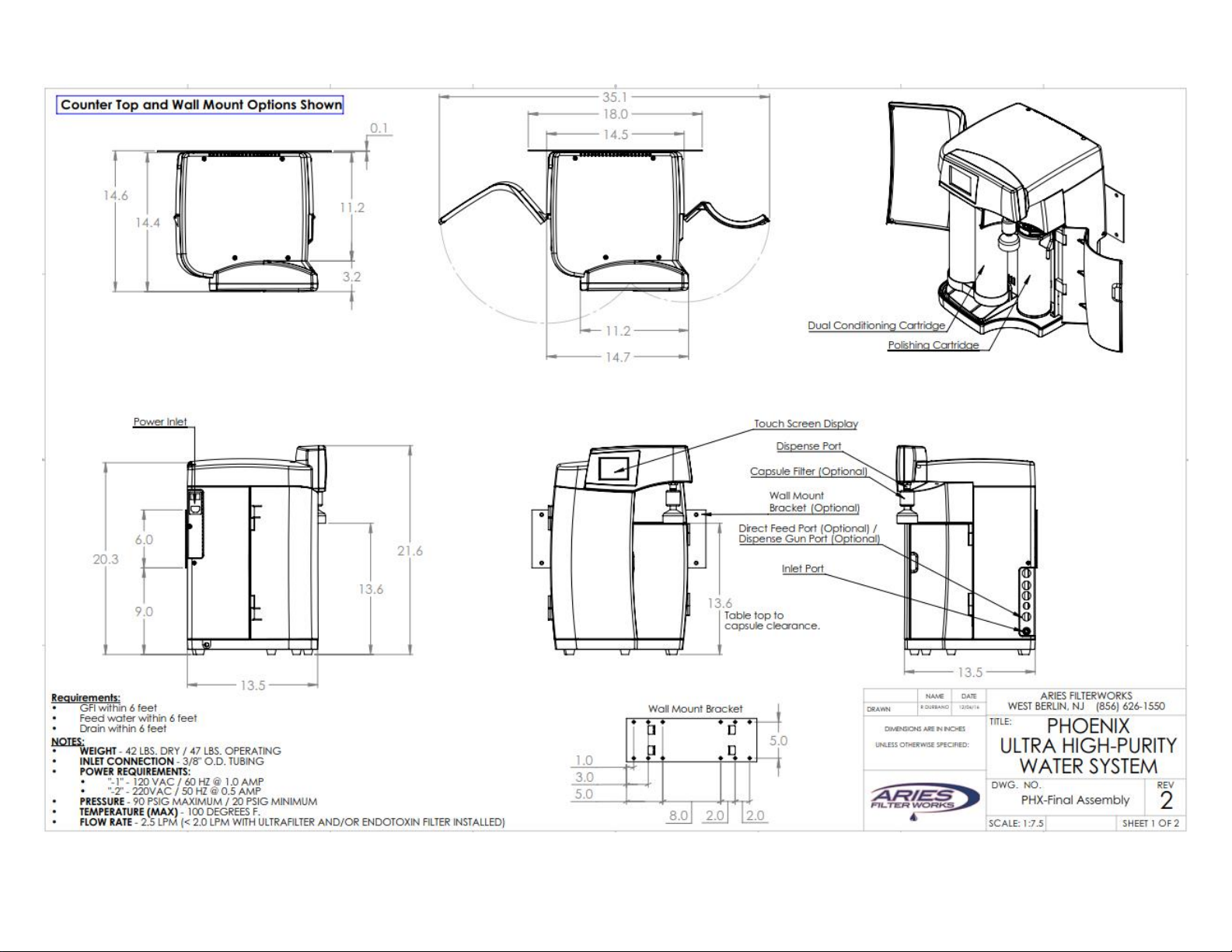
General Arrangement
Touch Screen Display
Power Input/Power Switch
Water Dispense Port
Feed Water Inlet
Conditioning
Cartridge
Polishing
Cartridge
Drain Port
Page 5
5
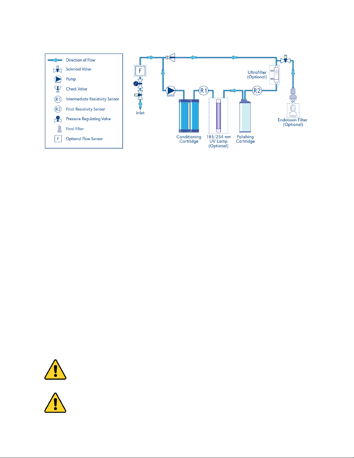
Flow Diagram
Safety Information
DO NOT immerse in water or other liquid. Use a soft cloth and mild detergent when cleaning the
cabinet.
DO NOT remove the top cover with unit power applied.
DO NOT remove the ultraviolet lamp side cover with unit power applied.
DO NOT look directly at the ultraviolet lamp with unit power applied.
DO NOT operate with a damaged or frayed power cord. To disconnect the power cord, grip the plug
and pull it from the wall outlet, NEVER PULL ON CORD!
DO NOT use outdoors. This instrument is intended for commercial, industrial, institutional, and
professional use. Use of this product in a manner other than recommended may void the warranty.
DO NOT operate without proper connection to an adequate water supply and purged of air or damage
to the pump may occur.
DO NOT allow power cord to hang over the edge of a counter top or to touch hot surfaces. NOTE: If an
extension cord is used, verify that the rating of the extension cord is equal to or greater than the rating
of the instrument.
Refer servicing of a defective or damaged unit to the factory.
The use of filters or attachments not recommended by the manufacturer may adversely affect water
purity, cause damage, and void the warranty.
Avoid contacting the dispensing point with foreign materials or hands to prevent contamination.
WARNING Warnings indicate failing to observe instructions could result in injury or death.
CAUTION Cautions indicate failing to observe instructions could result in damage to
equipment.
Page 6
Page 7
7
See Mounting Bracket Template
Page 8
Installation
Installation Requirements
• Power Requirements:
o “-1” Option - 120 VAC/ 60 Hz @ 1.0 amp
o “-2” Option – 220VAC / 50 Hz @ 0.5 amp
• GFCI protected outlet within:
o 6 feet for system
WARNING: Must be a grounded electrical connection.
• Feed Water Supply: Water source meeting minimum requirements as shown
below and located within 3 feet of the system.
Parameter
Requirement
Source/Type
Reverse osmosis (RO) or Service deionization (SDI) preferred. 0.2µm
particulate prefiltering is recommended for SDI and tap water feeds.
Conductivity
RO: < 20µS/cm
SDI: > 1 MΩ (Resistivity)
TOC (Using appropriate
conditioning as necessary)
RO: < 50 ppb
SDI: < 200 ppb
Temperature
20° F to 100°F (5° C to 38°C)
Pressure
20 psig minimum/90 psig maximum (1.38 to 6.21 bar)
Fouling Index
Silt Density Index: < 3
Dissolved Carbon Dioxide
< 30 ppm
Free Chlorine
< .05 ppm
• An upstream isolation shut off valve is highly recommended to facilitate future
servicing
• The Phoenix is supplied with an inlet connection for 3/8” OD tubing
• The Phoenix is supplied with an outlet drain port for 3/8” OD tubing
What you will need:
• #2 Phillips Head Screw Driver
• Teflon Tape
• Upstream Isolation Valve (Recommended)
• Basic Hand Tools (Adjustable wrench)
What you’ll find in the box:
• Phoenix System
• Certificates of Conformance
• Instructions
• Power cord
• Final Filter (Point of Use Filter)
• Drain Fitting
• 6’ Length of 3/8” Diameter Inlet Tubing & Drain Tubing
Page 9
9
Optional (Depending on Model):
• UV Lamp (CITATION and GENOME)
• Dispensing Gun (PHA-DG)
• Remote dispense module and tubing (Models with –RMT-S Option)
• Wall mount bracket (PHA-WB)
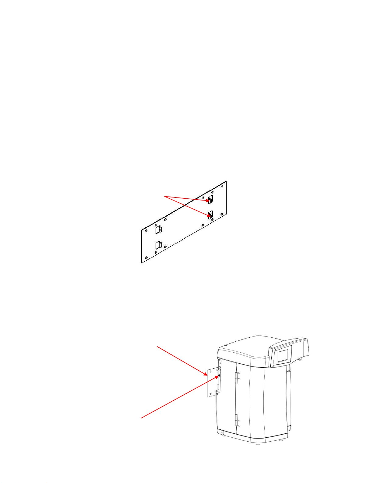
System Wall Mounting: Requires PHA-WB Wall Mount Bracket
• Mount on a wall capable of supporting 50 lbs. Mounting directly to sheet rock is not
recommended.
• Mount bracket to wall. Holes in bracket are provided at 8”, 12” and 16” centers for
wall studs. If wall does not have studs mount proper backing, such as a plywood sheet
to the wall before mounting the bracket to it.
• Mount bracket with small slots in tabs pointing up.
• Align slots in system back plate with tabs on mounting bracket. Insert tabs into slots
and slowly lower system. Ensure all tabs are fully engaged and base of system is
parallel to floor.
• To lock PHOENIX system to the bracket, insert rubber bushing with screw and washer
(provided) into frame as shown. Tighten screw to lock wall bracket to frame.
Wall mount bracket
Insert bushing assembly
here to lock system to
bracket
Tabs pointing up
Page 10
10
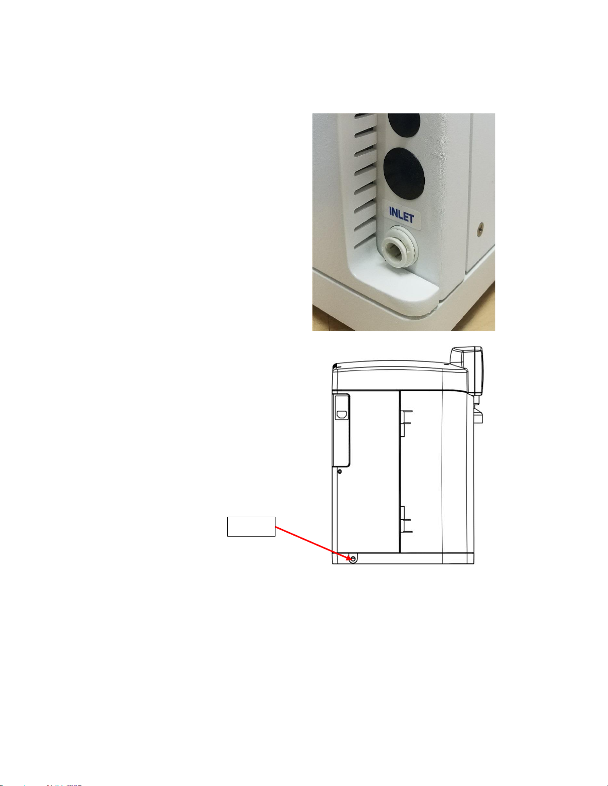
Water Connections – All Models
• 6 feet of tubing is provided for inlet
and drain connections.
• Feedwater inlet connection is made
through a 3/8” OD push to connect
fitting.
• Feedwater source should be located
within 3 feet of the Phoenix.
• The inlet is the bottom most fitting
on the right side of the Phoenix.
• Ensure tubing is pushed all the way
into fitting.
• An isolation shut off valve is
recommended for servicing purposes.
• Install supplied barbed drain fitting in
labeled drain opening on left side of
Phoenix.
• Insert 3/8” OD tubing (supplied) into
drain fitting and route the other end
to a suitable drain. If a leak occurs, it
will be contained by directing water
to the drain.
DRAIN
Page 11
11
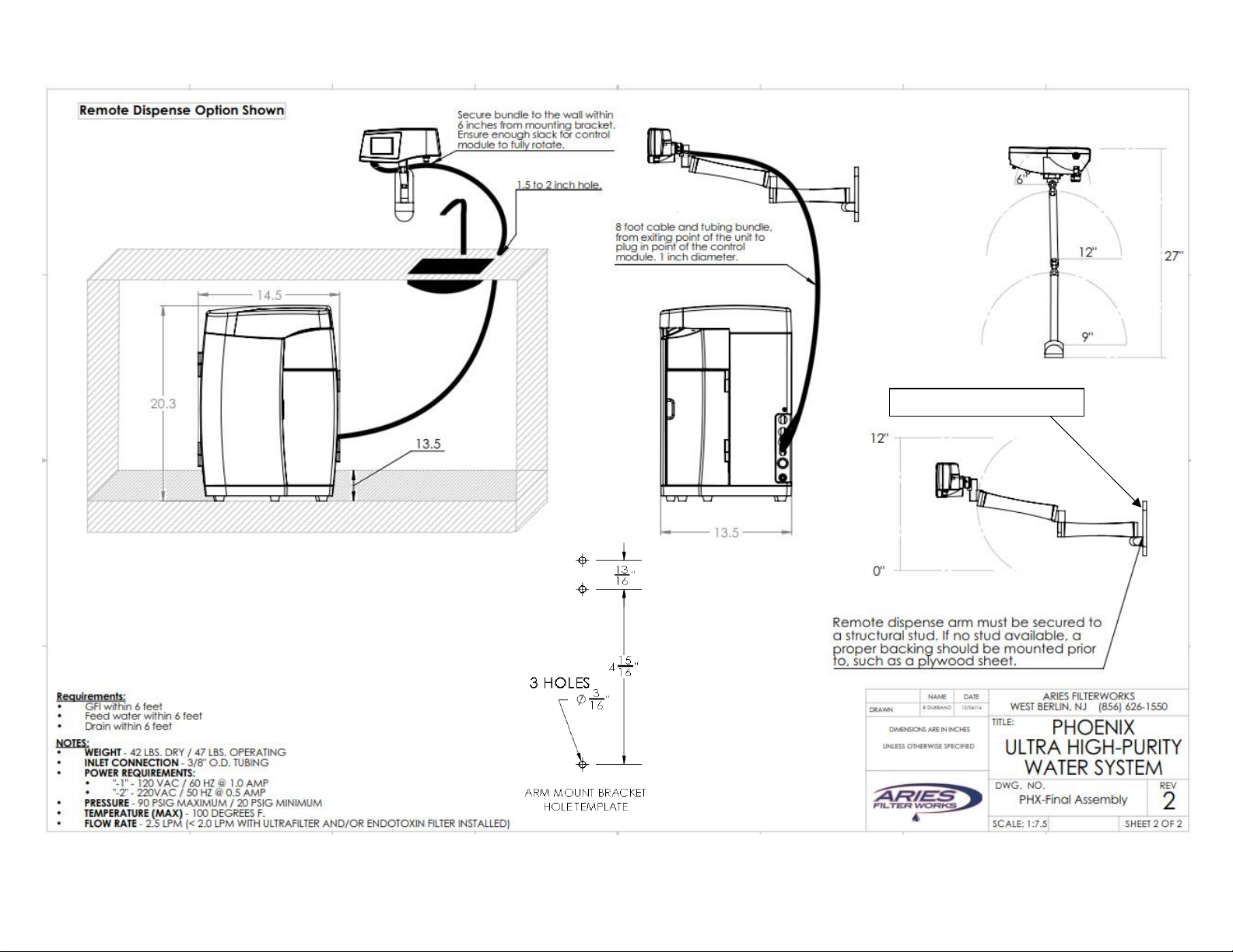
Remote Dispense (If Equipped)
Consideration should be given to location of the remote dispense module. Reference the diagram on
page 7. For example, the module can be mounted next to a sink so it would provide access to the sink
and adjacent countertop. The module can be mounted near the end of a countertop to provide access
to rolling carts for larger container fills as well as the countertop. Module should be mounted at a
height that provides access to the tallest container that will be used without blocking access to
cabinets.
For mounting the module, select a wall that is capable of supporting 20 lbs. The wall plate should be
mounted to a stud. Mounting directly to sheet rock is not recommended. If there is no stud at the
mounting location, mount proper backing such as a plywood sheet that is secured to studs before
mounting the plate to it.
Once a stud is located or support plate installed mark two holes on 5-13/16” centers and use a 3mm or
1/8” diameter drill to pre-drill holes to a depth of 2”. Use the two provided lag bolts to affix the plate.
While tightening the bolts ensure the mount is level.
10 feet of tubing is provided to connect the system and module. The system must located within this
distance bearing in mind that some slack should be allowed to provide access to the system for service.
Excess tubing can be coiled. 6 feet of drain tubing is also provided. Since the drain fitting is in the base
of the system, either access to a gravity fed floor drain or sump pump must be provided if the system is
installed below a sink. A 1-1/2” to 2” diameter hole must be provided where the umbilical containing
the water flow tubing and electrical connections will pass through a countertop.
Remote dispense electrical connection: Rotate connector to align tabs on umbilical plug with slots on
Phoenix socket and then insert plug. Repeat with the outer locking sleeve. When slots and tabs are
aligned, push and turn to lock connector in place.
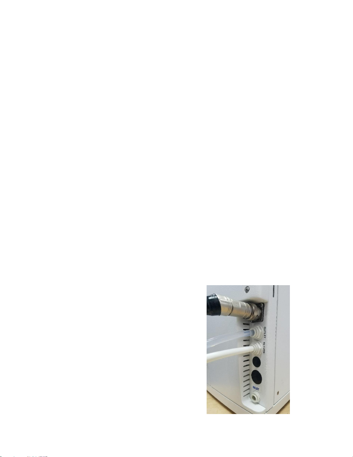
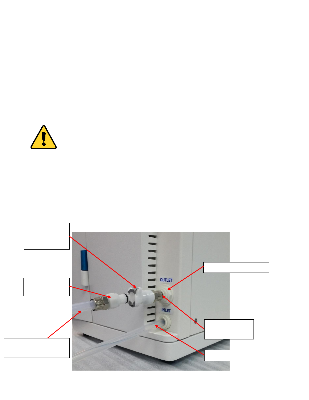
Remote Dispense Water Connections
• Install upstream isolation valve in
feedwater line (recommended).
• Connect 3/8” OD white recirculation
return tubing from umbilical into
Return fitting.
• Connect 3/8” OD clear tubing from
umbilical into Outlet fitting.
• Make sure tubing is fully seated into
fittings.
Page 12
12
Direct Feed Water Connection
For systems plumbed with a direct feed option, an additional outlet port is provided on the side of
the system above the feed water inlet. To connect the system to the remote demand, a
male/female valved fitting has been supplied. When the two halves are detached water will not
flow from the direct feed outlet port.
The female side has a short 3/8” tube extension. This tube is inserted into the outlet port.
The male side (with O Ring) is provided already attached to a length of 3/8” OD plastic tubing.
The direct feed connection must be bled during initial rinse after bleeding the
cartridges. Place the outlet end of the tubing in a drain or container. Insert and
connect the male/female fittings as shown. The female fitting has a metal locking
collar to prevent separation. Pull on the connection to verify it is engaged and does
not leak.
Observe the water stream. When air bubbles no longer appear disconnect the fittings.
It is the user’s responsibility to connect the outlet tubing to their demand instrumentation
providing appropriate sizing adapters as necessary. After doing so, reconnect the male and female
connectors.
Caution: Using the standard dispense port while the direct feed option is in use will reduce the
system flow rate.
`
Direct feed outlet port
System feedwater inlet
To direct feed demand
(tubing provided)
Male connector
(provided)
Valved female
connector
(provided)
Insert tubing end
into outlet port
Page 13
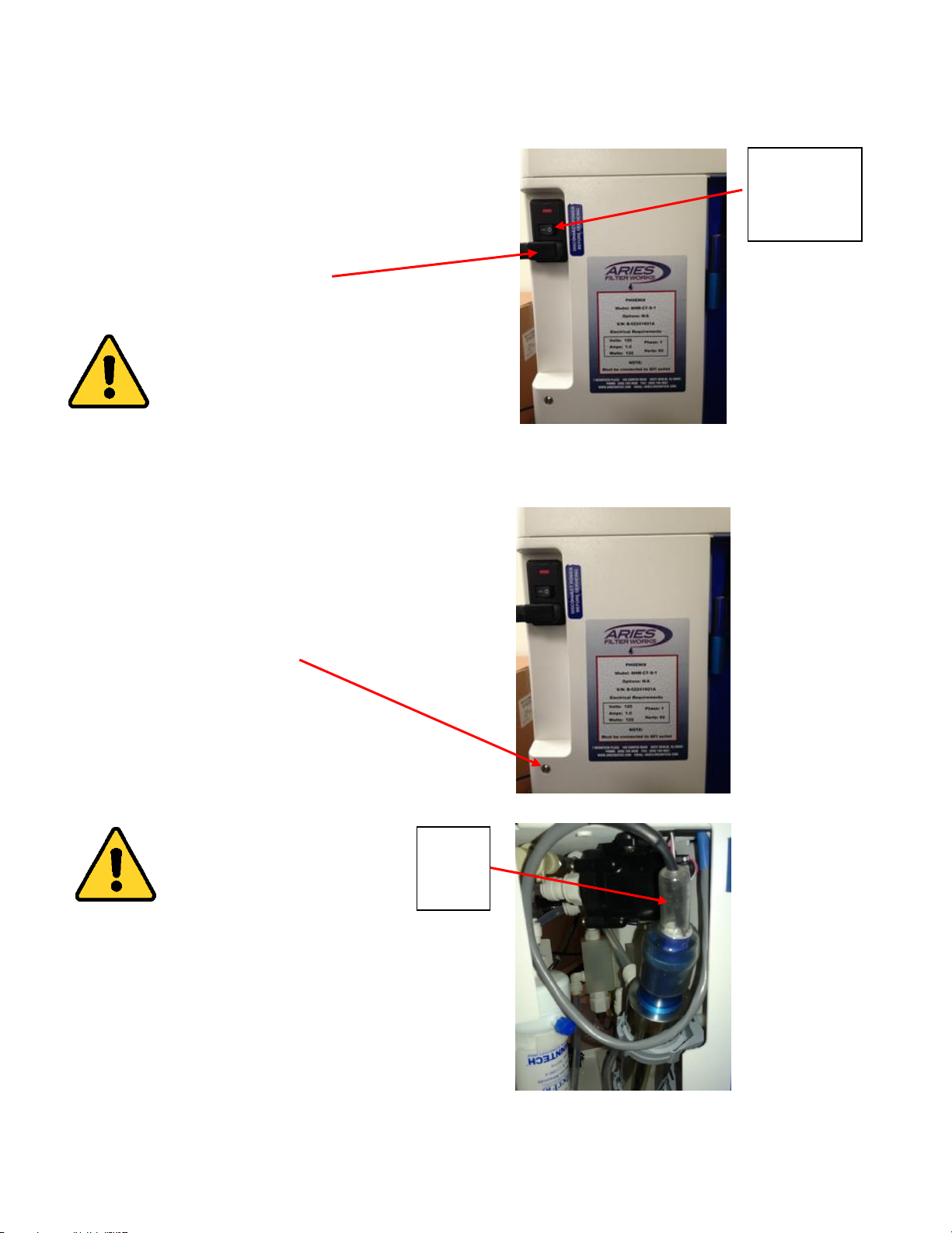
Electrical Connection
• Power switch is located on left side
of system
• Ensure power switch is in OFF
position
• Insert power cord into electrical
connection module
• Insert other end of cord into GFCI
power source
WARNING: Must be a grounded
electrical connection
UV Lamp (If not already installed) (ACADEMY and GENOME)
To install lamp:
• Remove left side panel access screw
• Remove left side panel
CAUTION: Wear gloves when
handling UV lamp to avoid
contaminating lamp
• Slide boot away from socket to
provide access for plug connection
• Connect lamp to socket before
placing lamp in UV chamber
• Insert lamp slowly into chamber
• Secure boot fully over socket
• Replace side panel
UV
lamp
boot
Electrical
connection
module
Page 14

14
Dual Conditioning Cartridge
• Remove cartridge from packaging
`
Caution: Remove plastic plugs
from inlet and outlet before
proceeding
• Open blue door and lift lever on left
side of dual conditioning cartridge
mechanism
• Insert conditioning cartridge. Align
base of cartridge with contour in
base of system
• Slowly lower lever making sure
fittings align with the openings in
the cartridge.
Caution: DO NOT APPLY
EXCESSIVE FORCE when
lowering lever or damage
may occur. Realign cartridge
and fittings if significant
resistance is felt.
• Ensure lever is in its fully down and
locked position
Page 15

15
Polishing Cartridge
• Remove cartridge from packaging
Caution: Remove plastic plugs
from inlet and outlet before
proceeding
• Open right side white door (It may be
convenient to open blue door as well)
• Raise and hold lever on right side of
mechanism
• Insert cartridge with openings facing
system
• Flanges on sides of cartridge cap rest
on alignment guide
• Push cartridge toward system until it
stops
• Slowly lower lever to secure cartridge.
Cartridge will be drawn into final
position by mechanism
• Ensure lever is in its fully down and
locked position
Alignment
guide
Page 16

16
Initializing the System for the First Time
Note: This is for the first time set-up only. In the on-screen directions you will be skipping steps
that would normally be required during consumable replacement.
Note: Some steps are applicable only to individual PHOENIX models. If your PHOENIX does not
have a UV lamp and/or Ultrafilter, these components will be greyed out on the Home Screen
Display.
• Ensure feed water supply is on and connected to system.
• Turn on power switch. Splash screen will display.
• Press START. Home Screen will display.
• After a 10 second delay, the pump will start and the system will begin the initial rinse cycle.
TO ACTIVATE THE ULTRAFILTER FOR BIOCHEM AND GENOME Models:
• Press and hold the ULTRA FILTER icon and press NEXT to initialize the Ultra Filter.
• Follow the instructions displayed.
o Skip on-screen instruction for Steps 5 and 6 as the ultrafilter is already installed.
o During Step 9, the purging process may take several minutes.
o Complete the procedure by pressing RESTART to return to the Home Screen.
TO ACTIVATE THE UV LAMP FOR CITATION and GENOME Models:
• From the Home Screen, press and hold the UV LAMP icon. Press NEXT to continue.
o Follow instructions displayed. It will not be necessary to replace lamp.
o Complete the procedure by pressing RESTART to return to the Home Screen.
TO ACTIVATE THE FILTER PACKS FOR ALL MODELS:
• From the Home Screen, press and hold the CONDITIONING icon. Press NEXT to continue.
o Follow instructions displayed. As this is the first time initialization process a new
pack should have been installed. It will not be necessary to replace the pack as
specified in the instructions.
o Complete the procedure by pressing RESTART to return to the Home Screen.
• From the Home Screen, press and hold the POLISHING icon. Press NEXT to continue.
o Follow instructions displayed. As this is the first time initialization process a new
filter should have been installed. It will not be necessary to replace the filter as
specified in the instructions.
o Complete the procedure by pressing RESTART to return to the Home Screen.
Page 17

17
• Remove the final filter from its packaging
• Wrap 3 to 5 turns of Teflon tape on the filter threads and install into the outlet.
o Place container under final filter.
o Press the dispense button.
o Purge air by slowly turning the vent port CCW until a steady stream of water is seen.
o Press the dispense button and retighten vent port once all air is purged.
Vent
Final filter (Point of Use Filter)
Page 18

18
Normal Operation
Normal sequence of operation:
Resistivity display will flash during the 2 hour initial rinse. After completion, the system enters
Polishing mode for 2 minutes in which the inlet solenoid is open and the pump is on. The UV lamp
is also on if equipped. Polishing mode recirculates water internally to maintain water purity. The
system continuously monitors water quality, system performance and consumable health. System
parameters for recirculation can be adjusted. See “Adjusting Recirculation Options”.
NOTE: Initial rinse can be bypassed to enter Polishing mode by holding the Initial Rinse button at
the bottom of the display for 3 seconds. This is useful if the system is restarted with previously
rinsed consumable packs.
Following Polishing, the system will automatically enter Standby mode and will display WAKE. This
is a 10 minute dwell to conserve system power and consumables. If equipped, the UV lamp is also
turned off. Standby mode can be bypassed by pressing the WAKE button to refresh water before
dispensing. If not bypassed the system will automatically enter Polishing mode at the end of the
dwell and will continue to alternate between Polishing and Standby.
Dispensing water will bring the system into Polishing mode if it is in Standby.
Final water quality after the Polishing filter (resistivity) is shown on the Home Screen. The value is
shown against a white background. Resistivity at the output of the conditioning pack can be
displayed by pressing the resistivity value. The display will change to a colored background
indicating it is the value after the conditioning pack. The display will return to final output water
quality after 5 seconds.
Direct feed operation (If equipped):
The system is equipped with a pressure switch that senses downstream water demand. When this
occurs the system enters direct feed mode and Direct Feed will display. The inlet solenoid and
pump will come on and remain running. The system will monitor the direct feed pressure and will
enter Polishing mode when demand stops for more than one minute.
Caution: The direct feed outlet connection must be bled during initial rinse after
bleeding the Dual Conditioning Cartridge and Polishing Cartridge. See the Direct
Feed Connection Section.
Water can be dispensed from the main outlet port during direct feed operation.
Page 19
19
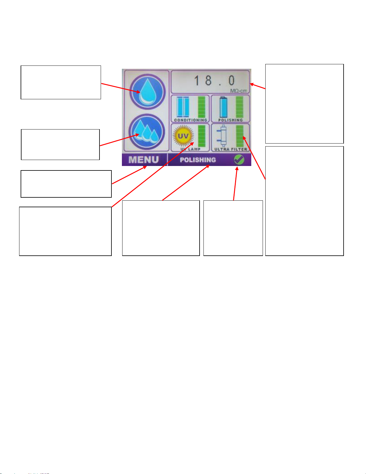
Home Screen
RECIRCULATION MODE
• INITIAL RINSE
• POLISH
• STANDBY
• DIRECT FEED
DISPENSE
Press to toggle
dispensing of water
RESISTIVITY
Displays Polishing
Cartridge resistivity.
Press to display
Conditioning Cartridge
resistivity. Press and
hold to display Alarm
set points
CONSUMABLE REPLACEMENT
ICONS
Press and hold any
component to display
replacement information
CONSUMABLE HEALTH
Displays current status
of consumables:
•
GREEN – Full life
•
YELLOW – Partial
life
•
RED – Needs
replacement
See MAINTENANCE
Section for more
details
BATCH
Press to display the
BATCH SELECT menu
MENU
Press to display Main Menu
ALARM STATUS
GREEN CHECK:
No Alarms
RED “X”:
Alarm present
Page 20

20
Batch Operations
To Dispense, Modify, Teach, Label or Clear a batch press the “Batch” button (the button showing 3 water
droplets). The Batch Select screen opens.
Main Screen
Batch Select Screen
To use a batch (1 through 6), to dispense a designated volume of water, press and release on its number
icon on the Batch Select screen.
To modify / teach / clear / label a batch, press and hold (about 3 seconds) the desired batch number icon
until a long beep is heard. The Batch Edit screen opens.
Batch
Button
Batch
Number
Icon
Displays Polishing
Cartridge resistivity
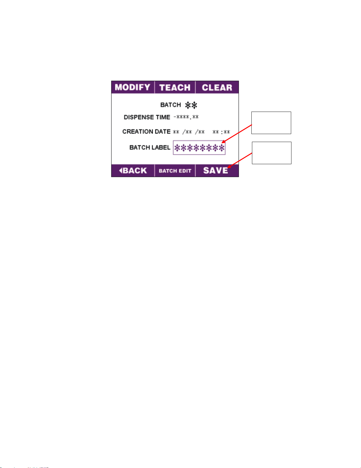
Page 21

21
Here a batch can be:
• Modified – changing a pre-recorded dispense time.
• Taught – manually dispense water while the system records the time. This will enable repeated
dispensing of a specific volume of water.
• Cleared – deleting saved batch information.
• Labeled – giving a specific batch a name.
• Saved – saving input information for future use.
Batch Edit Screen
To teach a batch, press the “Teach” button on the Batch Edit screen. The Batch Teach screen will appear.
• Place a volume measuring container capable of holding the desired volume underneath the
dispensing point of the system.
• Press the dispense button to begin flow.
• Monitor the volume output.
• Once the desired amount is reached, press the dispense button again. The system will
automatically retain the amount of time the dispense button was active, and return to the “Batch
Edit” screen.
Batch Teach Screen
Dispense
Button
Page 22

22
To modify a batch, press the “Modify” button on the Batch Edit screen. The Batch Modify screen will appear.
There are two ways to adjust the dispense time on this screen.
• Press the up and down buttons until the desired time (in seconds) is displayed.
Or:
• Press inside the time display box. Once pressed, a keypad will appear. Enter the desired time (in
seconds) and then press “ENT”. The system will return to the Batch Modify screen.
• Once the dispensing time is set, press “Enter”.
• The system will return to the Batch Edit screen.
Batch Modify Screen
To clear a batch, press the “Clear” button on the Batch Edit screen. The Batch Clear screen will appear.
• Press the “Clear” button. The saved information will be cleared.
• The system will return to the Batch Edit screen.
Batch Clear Screen
Up &
Down
Time
Page 23
23
To Label a batch, press inside the “Batch Label” box.
• A keypad will appear, allowing you to enter in a desired name using up to 8 characters.
• Press “ENT” when done. The system will return to the Batch Edit screen.
To save new batch information or to complete batch deletion, press and hold the “Save” button on the
Batch Edit screen for 3 seconds until a long beep is heard. The system will return to the Batch Select
screen. If label was assigned, it will appear under the specific batch number icon. By pressing and
releasing the icon the modified/taught batch will dispense.
Batch
Label Box
Save
Button
Page 24
24
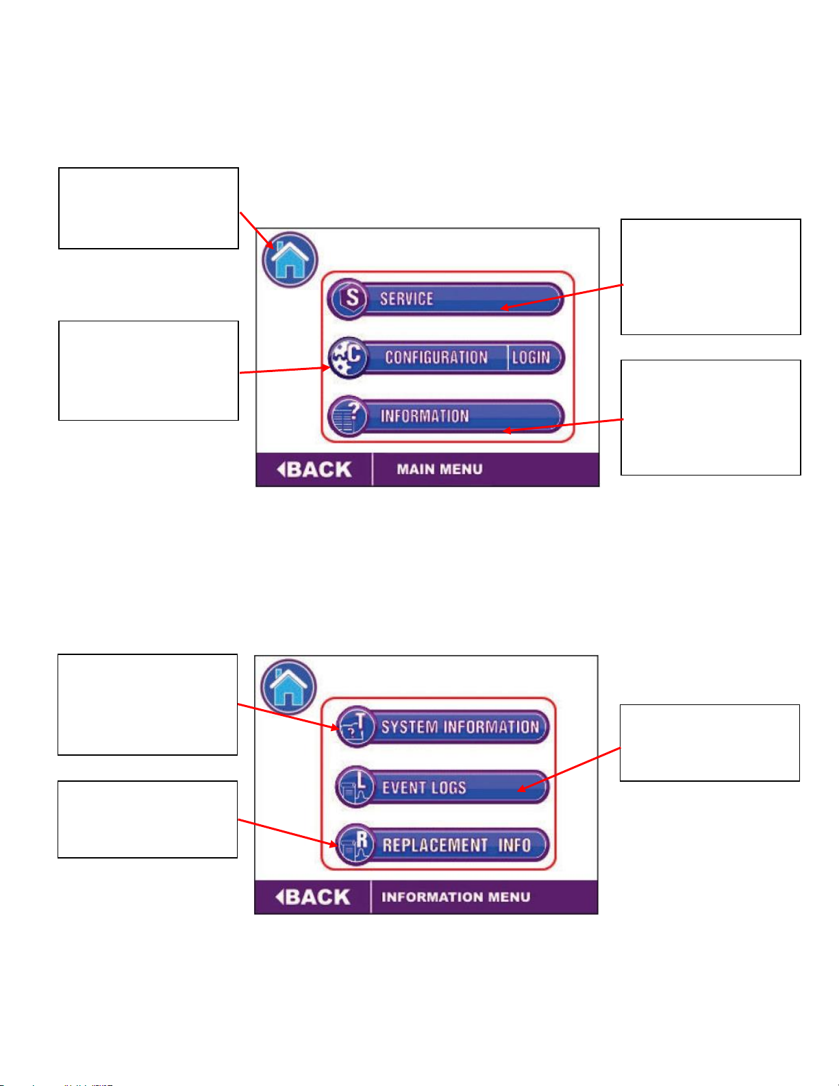
Main Menu
System Information
SERVICE
Displays Consumable
Replacement,
Sanitization, and
Service Information
HOME
Press to return to the
Home Screen
INFORMATION
Displays System
Information, Event
Logs, and Replacement
Info options
CONFIGURATION
Displays Alarm Setup,
Recirculation, and
Password options
SYSTEM INFORMATION
Displays system and
service contact
information
REPLACEMENT INFO
Displays projected
service dates
EVENT LOGS
Displays maintenance
log and alarm log
Page 25

25
Configuration Menu
Alarm Log (Example Screen)
PASSWORD
Factory preset
password for service
personnel only.
ALARM SETUP
Set resistivity alarm
options for
conditioning and
polishing cartridges
RECIRCULATION
Set Initial rinse time,
polish time, standby
time and sample delay
CLEAR
Clears the selected line
RESET
Resets alarm
conditions displayed on
home screen
Page 26

26
Filter Detection and Leak Detection Errors
CAUTION: After pressing OVERRIDE, the leak detector will NOT shut down the unit
even if water is detected.
LEAK DETECTED ERROR – Indicates a leak has been detected. Press
RESOLVE when the leak has been fixed or press OVERRIDE to override the
error for the next 4 hours.
FILTER PACK ERROR – Indicates one of the cartridges is not correctly engaged in the
system. Once the cartridge is in place, the user can proceed to reset the system.
Page 27

27
Maintenance
The system continuously monitors approximate remaining life of cartridges, UV lamp and
Ultrafilter. Current consumable condition and water resistivity is displayed on the HOME SCREEN.
A Maintenance Log is provided in the software. If preferred, a Maintenance Log template is
provided as an addendum that can be copied for future use, printed and distributed as required.
Sample software maintenance log
ALL MODELS:
Cartridge life is determined by a combination of elapsed time since installation and water
resistivity. The point at which the conditioning pack and polishing filter transition from green
health status to yellow can be adjusted. See the next section for adjustment instructions.
See the table below for default health meter resistivity settings:
Cartridge
Resistivity
Health Meter Color
Conditioning
> 12 MegΩ
Green
Between 2 MegΩ and 12 MegΩ
Yellow*
< 2 MegΩ (default alarm set point)
Red
Polishing
> 16 MegΩ
Green
Between 10 MegΩ and 16 MegΩ
Yellow*
< 10 MegΩ (default alarm set point)
Red
*If set point is adjusted, (see Resistivity Alarm Setup), yellow health meter color will appear at the
new set point.
Typical conditioning and polishing cartridge life is estimated at 4 - 6 months from date of
installation depending on usage. After six months a cartridge replacement alarm will be displayed.
It is the user’s prerogative to replace cartridges bearing in mind the currently displayed water
resistivity may still be acceptable. It is highly recommended cartridges be replaced at six months to
prevent biofilm generation that may occur over time.
Page 28

28
CITATION and GENOME:
UV lamp life is estimated at 2 years of normal use from date of installation. The UV lamp health
meter on the HOME SCREEN displays the proportional remaining life in this 2 year period as shown
below:
UV Lamp
Life Remaining
Health Meter Color
> 2 months
Green
Between 1 month and 2 months
Yellow
< 1 Month
Red
A replacement alarm will be displayed at 1 month remaining. It is recommended that the UV lamp
be replaced at that time to maintain low TOC levels.
GENOME Model:
Ultrafilter life is estimated at 1 year of normal use from date of installation. The Ultrafilter health
meter on the HOME SCREEN displays the proportional remaining life over this time period as
shown below:
0.05µm Ultrafilter
Life Remaining
Health Meter Color
> 6 months
Green
Between 1 months and 6 months
Yellow
< 1 Months
Red
A replacement alarm will be displayed at 2 months remaining. It is recommended the Ultrafilter be
replaced at that time to maintain acceptable bioburden.
Adjusting Resistivity Alarm Set Points
The point at which the conditioning pack and polishing filter transition from green health status to yellow
can be adjusted. Note: Software allows for a 2 MΩ range above the set point in which to change the health
meter display. Always make the set point 2MΩ below the desired display transition resistance. Maximum
set point allowed for conditioning is 10 MΩ and 14 MΩ for polishing.
To adjust the set points:
• Home Screen – Press Menu
• Main Menu – Press Configuration
• Configuration Menu – Press Alarm Setup
• Press appropriate field box; key pad will open
• Adjust values as required
• Press ENT to exit key pad
• Press and hold SAVE until beep is heard
• Press Home icon to return to Home Screen
Page 29

29
Adjusting Recirculation Options
The following operating parameters can be adjusted:
Initial Rinse – The time the system recirculates when restarted before converting to alternating
polishing and standby cycling. Default setting is 120 minutes.
NOTE: Initial rinse can be bypassed to enter Polishing mode by holding the Initial Rinse button at
the bottom of the display for 3 seconds. This is useful if the system is restarted with previously
rinsed consumable packs.
Polish Time – The time the system recirculates water to maintain purity. Default setting 2 minutes
Standby Time – Dwell time between polishing cycles to conserve resin life. Default setting 10
minutes
Sample Delay – The amount of time the system alternates between reading resistivity at the output
of the conditioning pack and the final water quality at the output of the polishing filter. Default
time is 10 seconds.
To adjust settings:
• Home Screen – Press Menu
• Main Menu – Press Configuration
• Press the appropriate field box; key pad will open
• Adjust value as required
• Press ENT to exit key pad
• Press and hold SAVE until beep is heard
• Press BACK to return to Configuration Menu
Press to adjust
conditioning
cartridge set point
Press to adjust
polishing filter set
point
Page 30

30
Sanitization
Sanitization is performed by circulating a chlorine dioxide (ClO2) solution throughout the system in
three sequential cycles of 10 minute dwell (standby) and 5 minute recirculation.
A sanitization kit is installed that contains the ClO2 in deactivated, packet form sealed inside a
polishing filter housing. It is not fully activated until exposed to water for approximately 20
minutes during the sanitization cycle. Under these conditions the sanitization kit is safe for
handling and installation without specialized PPE.
WARNING
Do not remove the orange sealing plugs from the sanitization polishing filter
housing until just before installation. If removed, moisture from the
environment will begin activation of the ClO2.
To begin the Sanitization cycle:
• Home Screen – Press Menu
• Main Menu – Press Service
• Service Menu – Press Sanitization
• Sanitization Information Screen – Press NEXT
• Sanitization Maintenance Screen – Follow on-screen directions
On-screen instructions call for installation of the kit. The kit contains a polishing filter replacement
housing that contains the ClO2 packet. NOTE: Save the orange plugs after removal from the
polishing filter housing. They will be used after sanitization to dispose of the filter.
The kit also contains a bypass tube that replaces the conditioning pack. This reduces the system
volume and speeds the overall sanitization process. To install the bypass tube after removing the
conditioning pack:
Page 31

31
Lower the conditioning pack lever to
expose the connectors and position the
bypass tube.
The locking tabs on the bypass tube
fittings should be facing outward
(towards you).
Insert one side of the bypass tube into
the connector until the locking tab
snaps into position. It will be necessary
to exert downward pressure on the
inner “U” frame to make this
connection.
Insert the other side of the bypass tube
until the locking tab snaps into
position. It will be necessary to exert
downward pressure on the inner “U”
frame to make this connection.
To remove the bypass tube after
sanitization, depress and hold each
locking tab and pull downward on the
tube to disconnect. Wear gloves
provided.
Connector
Lever
Locking tab
Bypass tube
Page 32

32
Sampling and completion of Sanitization:
• When you reach Sanitization Instruction Screen 5 you will start the 45 minute cycle by pressing
START CYCLE. The display shows the time remaining in the cycle.
• As water enters the polishing filter housing it will begin to activate the ClCO2.
• Install the supplied 3/8” barbed fitting into the dispense solenoid valve (where the POU filter was
removed)
• 6 feet of 3/8” ID clear vinyl tubing is provided in the kit. Connect the tubing to the barbed fitting.
Place the other end in a drain. NOTE: Insert the tubing directly into the drain, if possible, to
minimize odors.
WARNING
Chlorine dioxide gas is a respiratory irritant. Avoid breathing fumes. Ensure
area is sufficiently ventilated.
• When 20 - 25 minutes remaining is displayed put on gloves provided in the kit and dispense a small
amount of water from the drain tubing into a small, clean container. Do not allow tubing to touch
the collected water. Replace the tubing into the drain.
• Chlorine Dioxide test strips are provided in the kit. Use the white vial high range test strips to
confirm a minimum of 30 ppm chlorine in the sample by dipping a strip into the sample container.
Do not place the test strip directly under the running dispense water stream. Run water from the
sink when disposing of the water sample to minimize odor.
• When the cycle ends, follow instructions to dispense 2 – 4 liters of water to drain. Wearing gloves,
take an additional water sample from the drain tubing into a small, clean container as above and use
the blue vial low range test strips to confirm <10 ppm of chlorine. If a greater amount is present
dispense an additional 2 – 4 liters and retest. Continue this process until <10 ppm is obtained.
• Follow on-screen instructions to return system to normal operation.
NOTE: Dispose of the polishing filter by emptying into a sink while flushing with tap water or by
replacing the orange plugs and discarding. In this case no additional precautions are required. If
emptying, replace orange plugs before discarding.
Blue vial test strips for low range chlorine
White vial test strips for high range chlorine
Page 33

33
Troubleshooting
This troubleshooting guide contains information that pertains to all PHOENIX models. Some
symptoms and remedies refer to specific models based on their installed technology.
TROUBLESHOOTING GUIDE
SYMPTOM
CAUSE
REMEDY
Display is off.
No power to the unit or
unit in Stand By mode.
Check that the unit is plugged
into a live outlet.
Check the unit’s fuse – replace it
if it is blown.
Unit blows fuses.
An electrical short exists
in the unit or there is a
defective component.
Return the unit to the factory for
repairs or have the unit serviced
by an authorized dealer.
Unit will not dispense
water.
Supply water is not on.
Confirm that the supply water is
turned on.
A cartridge is loaded
with particles and is
plugged.
Replace the cartridge(s).
Air trapped in the
system.
Refer to symptom “Air is getting
trapped in system”
Defective solenoid
valve.
Have unit serviced by an
authorized dealer or return to
factory.
Low flow rate.
Water supply is
blocked.
Clear restriction or check water
supply.
Air is getting trapped in
the system.
Refer to symptom “Air is getting
trapped in system”
Sub-micron point of use
filter is clogged.
It is recommended to replace
sub-micron filters at scheduled
intervals not to exceed one year.
Low water pressure.
If line pressure is below 30 psi,
install booster pump.
Display indicates water
purity is below set-point.
The supply water is
improperly treated.
Measure supply water TDS in
grains per gallon, ppm, or mg/L
and compare to system spec
sheet requirements. Add
additional pretreatment to
obtain higher quality.
Resin is exhausted.
Install fresh cartridges.
Page 34

34
SYMPTOM
CAUSE
REMEDY
Resin cartridges exhaust
quickly.
Improper flow rate.
Check flow rate using a timed fill
test or by directly measuring with
an inline flow meter. Compare
results to filter or system spec
sheet and adjust flow as
necessary.
Internal pressure regulator may
be out of adjustment. Have unit
serviced by an authorized dealer
or return to factory.
The supply water has colloids
and is improperly treated.
Perform a Silt Density Test. If it is
higher than 1 add additional
pretreatment.
Bacteria exceeds operating
specifications.
UV lamp is not working
(CITATION and GENOME)
Confirm lamp is functioning by
checking the LED indicator light
above conditioning pack.
Confirm lamp is seated in the
socket.
Confirm lamp has not been in
service for more than one (1)
year.
Replace lamp with part number
HPA-016
The system has been stagnant
for an excessive period of
time.
Follow sanitization procedure in
Menu using Sanitization Kit P/N
HPA-017
The feed water supply is
grossly fouled.
Sanitize feed water supply
system. Then follow sanitization
procedure in Menu using
Sanitization Kit P/N HPA-017
The system is fouled with
contaminants.
Replace the point of use 0.2
micron filter.
Replace cartridges according to
the product number appearing
on each cartridge.
Replace the internal 0.05 micron
filter. (BIO)
Replace the 0.2 micron filter
attached to the dispense gun
(systems with this option)
Pyrogen levels are
excessive after the optional
0.05 micron filter.
Contaminated 0.05 micron
ultrafilter.
Autoclave or replace the
Ultrafilter.
Page 35

35
SYMPTOM
CAUSE
REMEDY
Unit does not rinse-up to
desired resistivity.
New units or cartridge
replacements require more
time to rinse-up.
Allow more time when installing
or replacing media.
Use a hand-held resistivity meter
to check that the resistivity is
increasing over time
Air is getting trapped in the
system.
The system is open to
atmosphere.
Bleed air at high points in
plumbing system and/or filter
housing. Use vent valve supplied
where applicable.
Excessive flow, turbulence,
and/or cavitation can cause
gases to come out of solution.
Check flow and velocity
throughout system to ensure it
does not exceed filter
requirements or industry
standards.
The point of use 0.2 micron
filter is bound with air.
Bleed the filter by opening the
bleed valve and allowing water
to flow until all air is expelled.
The 0.05 micron filter is
bound with air. (BIOCHEM
and GENOME)
Bleed the filter by opening the
bleed valve and allowing
water to flow until all air is
expelled.
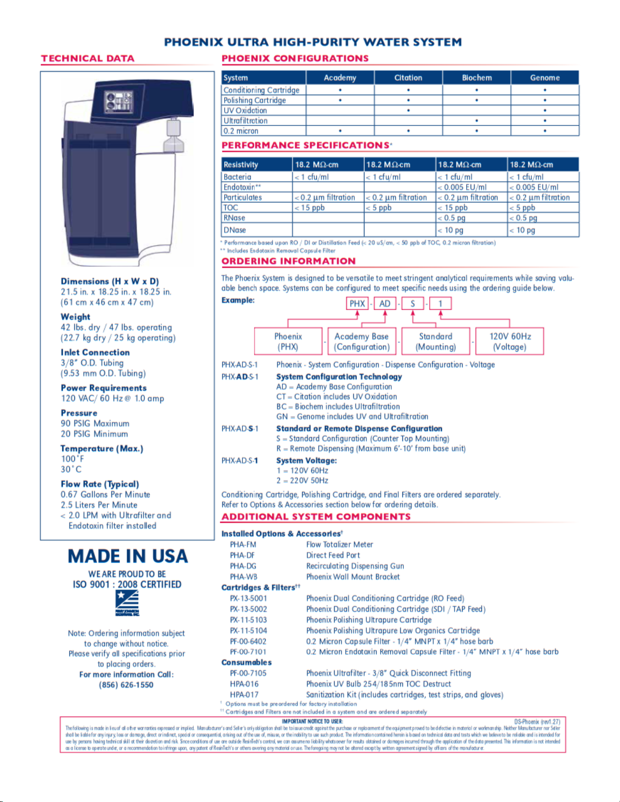
Page 36
Specification Sheet
Page 37
Page 38
38
Reordering Information
Cartridges and Filters
PX-13-5001
Phoenix Dual Conditioning Cartridge (RO Feed)
PX-13-5002
Phoenix Dual Conditioning Cartridge (SDI / Tap Water Feed)
PX-11-5103
Phoenix Polishing Ultrapure Cartridge
PX-11-5104
Phoenix Polishing Ultrapure Low Organics Cartridge
PF-00-6402
0.2µm Capsule Filter – ¼” MNPT x ¼” hose barb
PF-00-7101
0.2µm Endotoxin Removal Capsule Filter – ¼” MNPT x ¼” hose barb
Consumables
PF-00-7105
Phoenix Ultrafilter – 3/8 Quick Disconnect Fittings
HPA-016
Phoenix UV Bulb 254/185 nm TOC Destruction
HPA-017
Sanitization Kit (includes cartridges, test strips and gloves)
Requesting Service
Should the PHOENIX water purification system require maintenance or repairs not addressed in the
Troubleshooting or Maintenance routines, turn power to PHOENIX unit off and contact Technical Support
or your Service Professional
117 Jackson Road
West Berlin, NJ 08091
Phone: (856) 626-1550
Fax: (856) 626-1551
www.ariesfilterworks.com
Email: ariescs@resintech.com
Entering Your Service Professional’s Contact Info
You may add your Service Professional’s contact info on the Service Information screen as follows:
• Home Screen – Press Menu
• Main Menu – Press Information
• Information Menu – Press System Information
• Press Company Name field box; keypad appears
• Enter Service Contact’s Information; Press ENT to return to System Information Screen
• Press Phone Number field box; keypad appears
• Enter Service Contact’s Information; Press ENT to return to System Information Screen
• Press Home to return to the Home Screen
Be prepared to provide the representative with the model number, serial number, date of purchase and any
options that may have been purchased with or added to the unit after purchase; as recorded on page (3)
of this manual. This information may also be found on the system label.
Next, be prepared to describe to our service representative the symptoms that the unit exhibits.
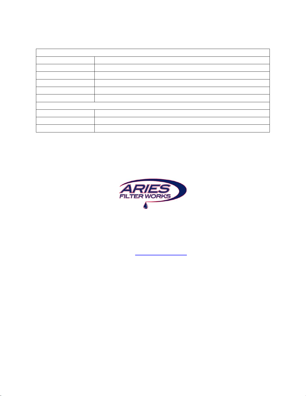
Page 39

PHOENIX WATER PURIFICATION SYSTEM MAINTENANCE LOG
S/N:
DATE INSTALLED:
ASSET # or ID:
LOCATION:
DATE
MAINTENANCE PERFORMED
BY
COMMENTS
Page 40

40
DATE
MAINTENANCE PERFORMED
BY
COMMENTS
Page 41

41
DATE
MAINTENANCE PERFORMED
BY
COMMENTS
 Loading...