

Phoenix 4800 E Owner's Manual
4201 Lien Rd. • Madison, WI 53704
Owner’s Manual — Phoenix 4800 E
Industrial Desiccant Dehumidifier
Installation, Operation & Service Instructions
Read and Save These Instructions
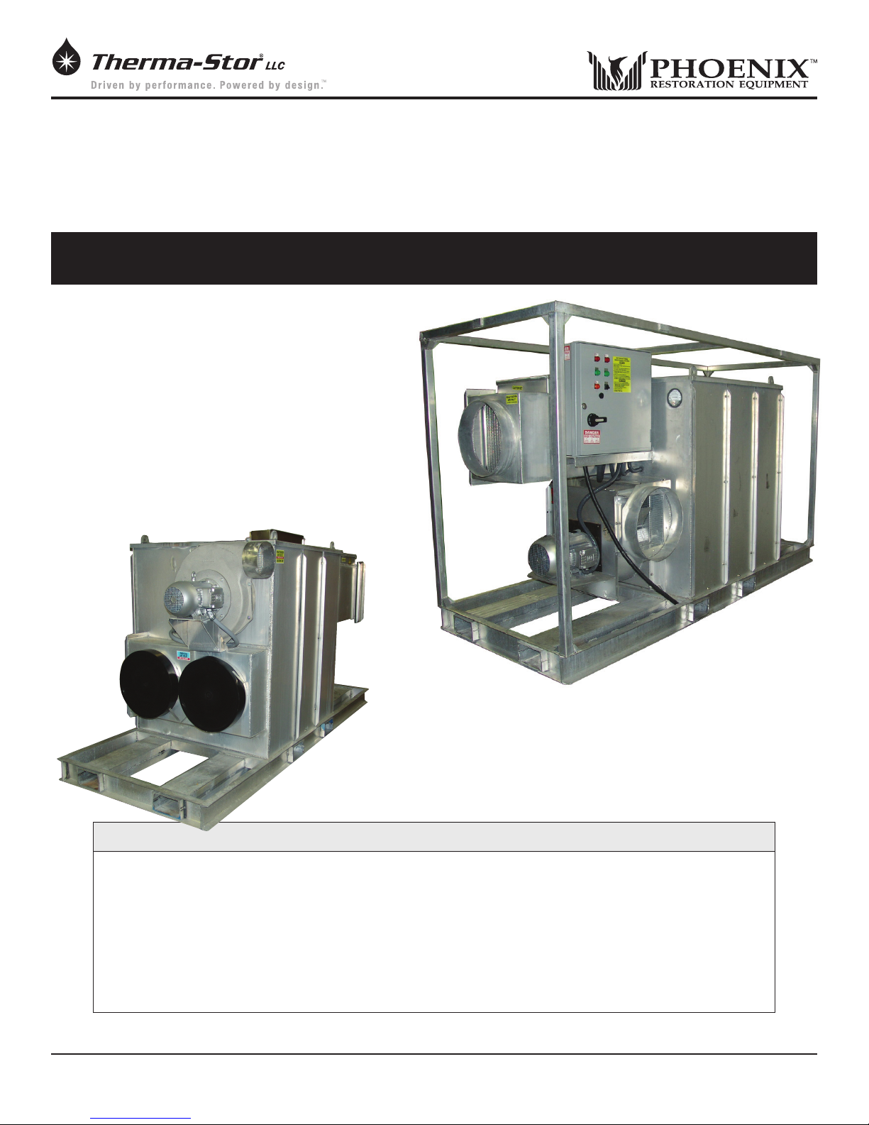
Congratulations on your purchase of the Phoenix 4800E
dehumidier. This dehumidier offers the nest in air-drying
equipment. However, this machine can only provide maximum
service and performance if properly installed, operated and
maintained.
This owner’s manual is provided to acquaint you with the
dehumidier so that the installation, operation and maintenance
can proceed successfully. Ultimate satisfaction depends on the
quality of the installation and thorough understanding of the
operation of this equipment. The dehumidier is built around
tested engineering principles and has passed a thorough
inspection for quality of workmanship and function.
• 3032 pints/day AHAM
• 4800 CFM process airow
• Dries in temperatures to 140ºF
• Reaches dew points as low as -40ºF
Specifications subject to change without notice.
Phoenix 4800E
(with Frame)
PN 4028003
Phoenix 4800E
(without Frame)
PN 4029191
The Phoenix 4800 E
• 48”W x 120”L x 74”H
• 1600 lbs. (Standard
machine weight only)
• 480 volt 3-phase
• 106 full load amps
TS-451d 06/11
1
www.UsePhoenix.com • sales@UsePhoenix.comToll-Free 1-800-533-7533

Table of Contents
Introduction .............................................................................1
1. Specications ..................................................................2
2. Operation .........................................................................2
2.1 How the Phoenix 4800E Works ............................... 3
3. Installation .......................................................................3
3.1 Inspection ..................................................................3
3.2 Location .....................................................................3
3.3 Set-Up.........................................................................3
3.4 Ducting ....................................................................... 4
3.5 Avoiding Secondary damage .................................... 4
3.6 Electrical Requirements ............................................4
4. Operation Instructions ....................................................4
4.1 Connect and Start-Up Procedure .............................4
4.2 Cool Down .................................................................. 5
4.3 Shut Down and Disconnect Procedure .................... 5
5. Control Panel ...................................................................5
5.1 Main Disconnect ........................................................5
5.2 Standby Light ............................................................. 5
5.3 Phase Out ..................................................................5
5.4 Selector Switch .......................................................... 5
5.5 Alarm (Light and Horn) .............................................. 5
5.6 Hour Meter ................................................................. 5
6. Maintenance .................................................................... 5
6.1 General Maintenance ...............................................5
6.2 Cabinet ....................................................................... 5
6.3 Filter ...........................................................................5
6.4 Blower and Motor ...................................................... 6
6.5 Drive Motor ................................................................ 6
6.6 Rotor Drive Chain ...................................................... 6
6.7 Seals ..........................................................................6
6.8 Desiccant Media .......................................................6
7. Wiring Diagram ...............................................................7
8. Trouble Shooting ............................................................10
9. Detailed Sequence of Events .......................................11
10. Service Parts List ...........................................................12
11. Warranty .........................................................................13
Serial No.__________________________________
Purchase Date_____________________________
1 Specifications
Specifications for 4800E
Part No. 4028003 (with Frame)
Part No. 4029191 (without Frame)
Power 480 VAC, 3-Phase, 106 FLA
Water 3032 pints/day @ AHAM
Removal
Blower 4800 CFM Process Air Flow
2000 CFM Reactivation Air Flow
Operating -10ºF to 140ºF
Range
Filters Process lter size: (2) 20” x 20” x 2”
Reactivation lter size: (1) 20” x 20” x 2”
Duct Options Process Inlet: 18” Flex-Duct
Process Outlet: 18” Flex-Duct/Lay Flat
Reactivation Inlet: 18” Flex-Duct
Reactivation Outlet: 10” Flex-Duct
Warranty 2 years:
1st year Parts and Service
2nd year Silica Gel Rotor
Dimensions
Width 48”
Height 74”
Length 120”
Weight 1600 lb
Accessories
4028361 10” Flex-Duct
4028364 18” Flex-Duct
4028374 18” Lay Flat Duct
4024440 Kestrel 3000 Multi-Function Air Meter
4027327 External Temperature control
4020175 External Dehumidistat
4029003 Power Cord Grip
Air Filter Replacement
4028635 20” x 20” x 2” Filter
Machine
Dealer’s Name_____________________________
Read the operation and maintenance instructions carefully
before using this unit. Proper adherence to these instructions
is essential to obtain maximum benet from your Phoenix
4800E.
2 Operation
The function of the dehumidier is to remove moisture (in
the vapor state) from an air stream. This is accomplished
by exposing the air to an adsorbing media (desiccant) in
a sealed air stream (process). After the desiccant has
2
www.UsePhoenix.com • sales@UsePhoenix.comToll-Free 1-800-533-7533
adsorbed moisture, it is exposed to a second air stream at an
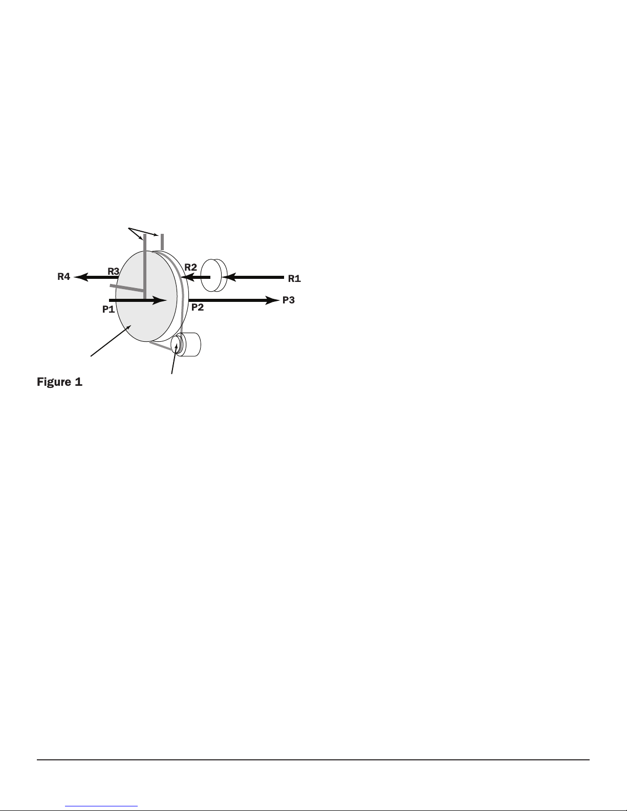
Principle of Operation
Drive and Chain
elevated temperature (reactivation). This causes the moisture
to be driven out of the desiccant preparing it for more
moisture adsorption. This process is done on a continuous
basis, providing a constant drying process. The two air
streams (process and reactivation) are separated by seals,
which contact the desiccant media. Figure 1 illustrates the
relationship of the seals and airow pattern. The dehumidier
is designed with the two air streams owing in opposite
directions (counter ow) thereby maximizing the energy
efciency of the equipment.
Cabinet Divider
and Seals
Heater
Reactivation Air Outlet
Reactivation Air Inlet
3 Installation
Proper installation is critical to the performance of the
Phoenix 4800E. Follow the guidelines below to maximize
service life and performance.
3.1 Inspection
Thoroughly inspect the machine to insure no damage has
occurred during shipping or on the job site.
3.2 Location
Note the following precautions when locating the Phoenix
4800E:
The 4800E is designed to be used indoors or outdoors.
If the humid area is very large, dehumidication can be
improved by adding an outlet duct to circulate process air to
stagnant areas.
Process Air Inlet
Process Air Outlet
Desiccant Wheel
Desiccant Wheel
2.1 How the Phoenix 4800E Works
The Phoenix 4800E has two separate air streams that run
through it – Process and Reactivation (Fig. 1).
Process Air Stream:
P1 – 4800 CFM of air enters the machine (Process Air Inlet)
and...
P2 – ...water vapor from incoming air is deposited (adsorbed)
on the desiccant wheel.
P3 – 4800 CFM of dry air exits the machine (Process Air
Outlet).
Reactivation Air Stream:
R1 – 2000 CFM of air enters the machine (Reactivation Air
Inlet) and...
R2 – passes over the heater coils.
R3 – Water vapor is picked up (desorbed) from the desiccant
wheel by the hot air and...
R4 – ... 2000 CFM of wet air exits the machine (Reactivation
Air Outlet).
3.3 Set-Up
When conditions warrant the use of a desiccant dehumidier,
use one of the setups described below to achieve efcient
drying, while avoiding secondary damage. Review Section
2.1 to understand the desiccant drying process. Always
ensure that the Reactivation Outlet duct is vented to the
outdoors to minimize the possibility of secondary damage.
Neutral Pressure Setup
Many drying applications require neutral pressure operation.
In this setup, the Process Air Inlet pulls air from the affected
area (drying chamber) and returns dried, processed air to the
affected area via the Process Air Outlet.
The Reactivation Air Inlet and Outlet are both ducted to the
outdoors (or left open if the unit is set up outside).
Positive Pressure Setup
For Positive Pressure operation, the Process Air Inlet pulls air
from outside the drying chamber, while the Process Air Outlet
is ducted into the chamber.
The Reactivation Air Inlet and Outlet are both ducted to the
outdoors (or left open if the unit is set up outside).
3
www.UsePhoenix.com • sales@UsePhoenix.comToll-Free 1-800-533-7533

3.4 Ducting
The duct requirements of the 4800E are much more critical
than those of refrigerant-based dehumidiers. ALL SUPPLY
AND RETURN AIR DUCTING FOR THE 4800E MUST BE
AIR AND VAPOR TIGHT. This is extremely important for
proper performance. Ensure that reactivation discharge air
does not enter the process or reactivation inlets.
Using excess duct length signicantly reduces air ow volume
through duct. This is true in any application. If the job at hand
needs a short length of duct, cut a section to the appropriate
length. If air ow is restricted by excess length, performance
will suffer. The same can be said of excess bends in the
ducting.
Two different duct sizes are used on the 4800E. All ducting
materials are available from Therma-Stor LLC
(see accessories list in Section 1).
Process inlet / Reactivation inlet: 18” flex duct.
To attach ex ducts to the process air intake, push the wire
of the rst few loops beyond the 2 holes in the duct collar.
Push the metal rod through the duct and duct collar piercing
the duct in two places. Tape or a hose clamp can be used
to create an airtight seal. Alternatively, the duct wire can be
pushed past the weld beads on the duct collar and the duct
can be secured with hose clamps or ratcheting straps. If
using only one inlet connection, the other can be left closed.
Process outlet: 18” flex or lay flat plastic duct.
To attach ex ducts to the process air outlet, push the wire
of the rst few loops beyond the 2 holes in the duct collar.
Push the metal rod through the duct and duct collar piercing
the duct in two places. Tape or a hose clamp can be used
to create an airtight seal. Alternatively, the duct wire can be
pushed past the weld beads on the duct collar and the duct
can be secured with hose clamps or ratcheting straps.
When using 18” lay at ducting, slip over the outlet collar and
zip-tie or duct tape in place.
Reactivation outlet: 10” flex duct.
To attach ex duct to the reactivation air outlet, push the
wire of the rst couple of loops beyond the weld beads on an
outlet collar. Secure with hose clamp.
3.5 Avoiding Secondary Damage
The Phoenix 4800E is a powerful tool capable of removing
a great deal of water from most environments. Care must
be taken to avoid secondary damage of over-drying and or
unexpected condensation.
The Phoenix 4800E removes vapor water from the
incoming process air stream and transfers it to the outgoing
reactivation air stream. The reactivation exhaust air is hot
and wet.
Take care to prevent the reactivation exhaust air stream from
causing secondary damage due to condensation.
If the exhaust from reactivation air stream cools below its
dew point, liquid water will condense inside the duct work
creating puddles. If the reactivation exhaust air stream is not
exhausted completely from the structure it can also cause
secondary water damage.
The Phoenix 4800E does not produce liquid water internal
to the machine. There is no condensate pump and no drain
hose.
The 4800E desiccant dehumidier will continue to remove
water from already dry, cold air. It is possible to over-dry
objects and or structures.
Care must be taken to avoid secondary damage due to overdrying.
3.6 Electrical Requirements
A 480 volt, 3 phase power source is required to operate the
Phoenix 4800E.
All local and state codes must be strictly adhered to and
good electrical practices should be followed to achieve the
best installation possible. The 4800E must be properly wired
to an adequate power source. Serious damage to the motors
and controls can occur if incorrect voltage is applied.
(See Electrical Schematic drawing in the back of this manual
for internal wiring.)
4 Operating Instructions
Refer to the Operating Instructions label located next to the
control panel of your 4800E.
User-supplied power cord, cord grip, and branch protection
appropriate for the electrical load must be supplied. See
device for FLA rating.
The Phoenix 4800E dehumidier comes complete and ready
for operation. All that is required is to provide the proper
power source and duct connections (described above).
4.1 Connect and Start-Up Procedure
1) Lockout Power Source.
2) Wire unit 480 Volt 3 Phase.
3) Verify Selector Switch is set to STANDBY.
4) Engage Power Source and turn Main Disconnect to ON.
5) Verify PHASE OUT light is off, if not, re-wire power
source to correct phase order.
6) COOL DOWN light will come on for 5 minutes.
7) Set Selector Switch to RUN.
8) Set process damper to obtain a maximum of 1.5”
water column pressure as read on pressure gauge.
4
www.UsePhoenix.com • sales@UsePhoenix.comToll-Free 1-800-533-7533
 Loading...