

Phoenix 200 MAX LGR, 200 MAX Owner's Manual
4201 Lien Rd. • Madison, WI 53704
Owner’s Manual — Phoenix 200 MAX
Installation, Operation & Service Instructions
Read and Save These Instructions
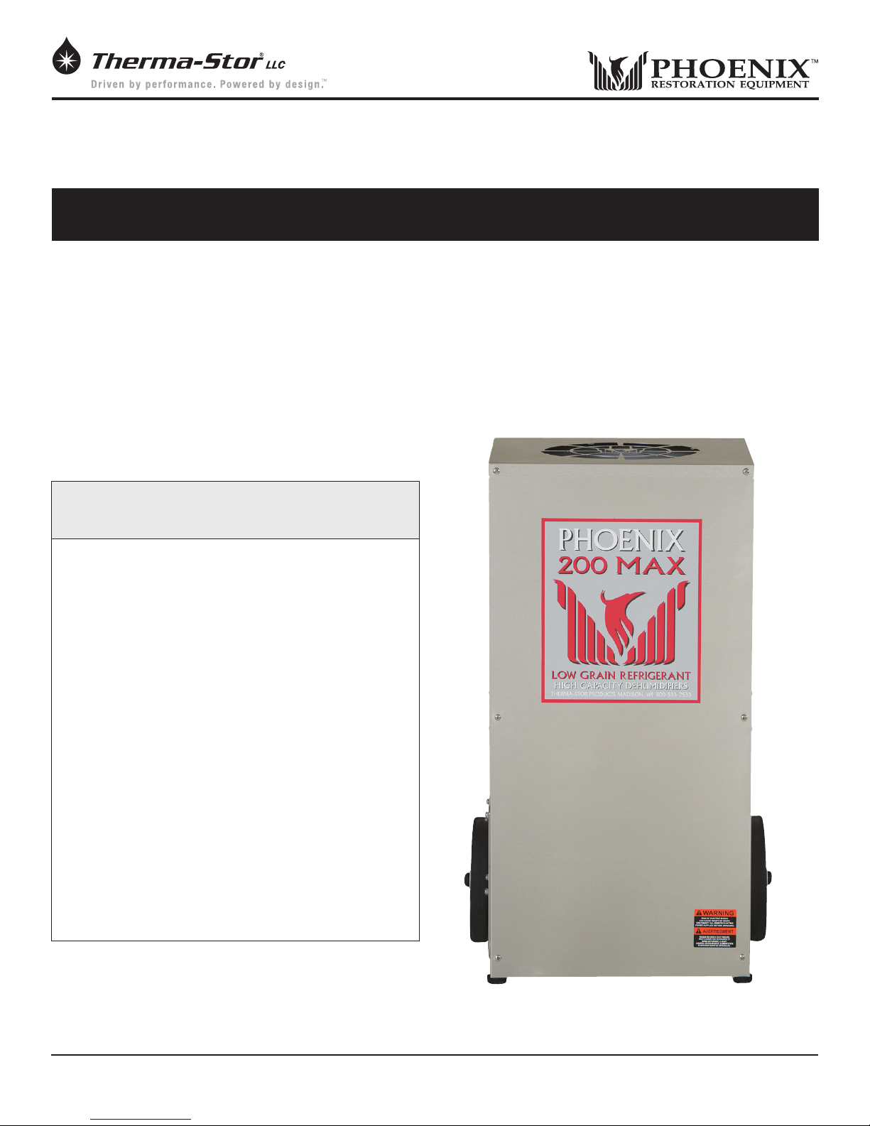
The Phoenix 200 MAX is one of the most effective and versatile drying devices available. The 200 MAX
removes more water and features better grain depression than other refrigerant dehumidiers, while
drawing only 7.4 amps of electricity.
The term LGR (Low Grain Refrigerant) was created to describe the unique drying capabilities of the
Phoenix 200 dehumidier. These units were known for delivering substantially drier air, as well as for
drying areas to much lower humidity levels than conventional dehumidiers. The Phoenix 200 MAX, an
improved version of the original Phoenix 200, is the culmination of over a decade of LGR manufacturing
and design expertise.
The Phoenix 200 MAX LGR,
High Capacity Dehumidier
• Improved water removal
16 gals/day (128 pints) AHAM (80ºF, 60%)
30 gals/day maximum
• Improved grain depression
The driest air from an LGR
• Multiple air lter options
Standard 65% MERV-11, or 95% MERV-14
• Multiple ducting options
12” intake, 10” lay-at exhaust
• Less than 7.5 amps
Removes the most pints of water per kilowatt
• Stainless steel cabinet
• Internal pump with 30 feet of hose
• Five-year warranty on the sealed refrigeration
system.
Specifications subject to change without notice.
Phoenix 200 MAX
PN 4029740
1
www.UsePhoenix.com • sales@UsePhoenix.comToll-Free 1-800-533-7533
TS-608
08/11

Table of Contents
Introduction ............................................................................. 1
1. Specications ..................................................................2
2. Operation .........................................................................2
2.1 Transporting the Phoenix 200 MAX ......................... 2
2.2 Location ..................................................................... 2
2.3 Electrical Requirements ............................................3
2.4 Condensate Removal ................................................3
2.5 Ducting ....................................................................... 3
2.6 Power Switch .............................................................3
2.7 Pump Purge Switch ................................................... 3
2.8 Hour Meter ................................................................. 3
2.9 Defrost Control Adjustment ......................................3
2.10 Low Pressure Control .............................................. 3
3. Maintenance .................................................................... 4
3.1 Air Filter ......................................................................4
3.2 Storage .......................................................................4
4. Service .............................................................................. 4
4.1 Warranty .....................................................................4
4.2 Technical Description ................................................4
4.3 Troubleshooting ......................................................... 5
4.4 Refrigerant Charging ................................................. 5
4.5 Blower Replacement ................................................. 5
4.6 Compressor/Capacitor Replacement ......................6
4.6A Checking Compressor Motor Circuits .............. 6
4.6B Replacing a Burned Out Compressor .............. 6
4.6C Replacing a Compressor- Non-Burn Out .......... 7
4.7 Defrost Thermostat & Timer ..................................... 7
4.8 Condensate Pump ..................................................... 7
4.9 Gravity Drain Option .................................................. 7
4.10 Relay.........................................................................7
5. Options and Accessories .................................................8
6. Wiring Diagram ...............................................................8
7. Service Parts List ............................................................. 9
Warranty .........................................................................10
Serial No. ___________________________
Purchase Date ______/______/_____
1 Specications
Part No. 4029740
Power 110-120 Vac, 7.4 amps; 851 watts
Water 128 pints/day @ AHAM (80°F, 60%)
Removal 240 pints/day @ saturation
30 gal/day maximum @ saturation
Refrigerant 1 lbs., 8 oz. R410a
Charge
Blower 290 CFM
Internal Condensate Pump with 20 lift,
30’ vinyl hose
Operating 33°F to 105°F
Range
Filters 16” x 20”
Optional 2” Pleated Media 30% MERV-8
Standard 2” Pleated Media 65% MERV-11
Optional 4” Mini-Pleat Media 95% MERV-14
Duct Intake – 12” Flex-Duct
Options Supply – 10” Lay-Flat
Warranty Five years;
First year 100% of Parts and Labor
Second-fth year 100% of Parts of sealed
refrigeration system.
Dimensions:
Dehumdier
Width 24”
Height 40”
Depth 21-3/8”
Weight 130 lb
2 Operation
2.1 Transporting the Phoenix
The Phoenix 200 MAX must always be upright when
transported by vehicle. It may be tipped on to its handle and
back for loading and moving by hand.
Dealer’s Name ___________________________________
Read the operation and maintenance instructions
carefully before using this unit. Proper adherence to these
instructions is essential to obtain maximum benefit from
your Phoenix 200 MAX dehumidifier.
2.2 Location
Note the following precautions when locating the Phoenix
200 MAX:
• It is designed to be used INDOORS ONLY.
• If used in a wet area, plug it into a GROUND FAULT
INTERRUPTER.
• DO NOT use the Phoenix 200 MAX as a bench or table.
• It must always be used in the upright position.
2
www.UsePhoenix.com • sales@UsePhoenix.comToll-Free 1-800-533-7533

• The air inlet on top & the side outlet must be at least
1 foot from walls and other obstructions to air ow.
• If the humid area is very large, dehumidication can
be improved by adding an outlet duct to circulate air to
stagnant areas (see Sec. 2.5).
2.3 Electrical Requirements
The Phoenix 200 MAX plugs into a common grounded outlet
on a 15 Amp circuit. It draws 7.4 Amps at 80°F,
60% RH. Amp draw increases with increasing temperature
and\or humidity. If used in a wet area, a ground fault
interrupter (GFI) is required.
If an extension cord is required, it must have a minimum of
14 gauge conductors if 25 feet long or less and 12 gauge
conductors if greater than 25 feet long.
2.8 Hour Meter
The digital hour meter measures the cumulative time that the
unit is turned on to tenths of an hour. It stores its total when
the unit is unplugged; the previous total will be displayed
when the unit is next turned on. It resets to zero after
99,999.9 hours of operation.
2.9 Defrost Control Adjustment
When the Phoenix 200 MAX is used in a cool area, or the
dewpoint is below 50°, frost will form on the cooling coil
as it dehumidies. When enough frost forms, the defrost
thermostat will initiate the timed defrost cycle. The cycle
periodically turns off the compressor while allowing the
blower to run. The frost is melted by the air that the blower
draws through the cooling coil.
2.4 Condensate Removal
The Phoenix 200 MAX is equipped with an internal
condensate pump to remove the water that is condensed
during dehumidication. This allows the condensate to be
pumped 30’ with the attached hose. If the condensate must
be pumped more than 20 feet above the unit, a second
pump must be added to relay the condensate. If the pump
fails and the unit must be used before it can be replaced, the
condensate can be drained by gravity (see Sec. 4.9).
2.5 Ducting
A detachable rectangular exhaust collar is supplied that will
allow 10” round lay-at duct to be attached to the Phoenix
200 MAX outlet. Lay-at plastic ducting is available from
Therma-Stor.
To attach ducting to a collar, put the plastic duct end
through the collar center and roll the duct end outward so
that it overlaps the outside of the collar. The duct and collar
may then be quickly attached to the Phoenix 200 MAX by
snapping the collar over the four screws at the blower outlet.
2.6 Power Switch
The power switch (right of hour meter) lights up when the unit
is turned on. The unit will continue to run in all conditions
until the switch is turned off; there is no dehumidistat. If
the unit is going to run for more than 2 hours in an area
below 50°F, the defrost timer should be adjusted to improve
performance (see Sec. 2.9).
DRYING TIP: Air’s ability to absorb moisture from wet
surroundings and the Phoenix 200 MAX’s ability to remove
moisture from that air is greatly improved at higher
temperatures. We recommend that the area to be dried be
heated to over 70°F if possible. Less drying time will be
required and efficiency will improve.
2.10 Low Pressure Control
If the low side refrigerant pressure drops to 35 PSIG, the
low pressure control opens and shuts off the compressor
and blower. It is an automatically reset control. Its primary
function is to prevent damage to the compressor if a leak
develops in the refrigeration system. It may also open if the
unit is A) used in a cool area (below 50°F) or B) stored where
it is below 40°F and then started. Under these conditions,
the unit will restart within several minutes; it may cycle
several times until the unit warms up.
2.7 Pump Purge Switch
This switch (left of hour meter) minimizes the water left
in the condensate pump reservoir for moving or storage.
Pressing and holding the pump purge switch will cause the
condensate pump to run. Hold the switch in until the ow
from the condensate hose stops.
3
www.UsePhoenix.com • sales@UsePhoenix.comToll-Free 1-800-533-7533
 Loading...