

Phoenix 200 HT LGR Owner's Manual
PO Box 8680 • Madison, WI 53708
Owner’s Manual — 200 HT LGR Dehumidifier
Installation, Operation and Service Instructions
Read and Save These Instructions
The Phoenix 200 HT features LGR (low grain refrigerant) technology. This technology enables the 200 HT to remove more
water and create more grain depression than standard refrigerant dehumidifiers.
Combined with this performance, the multiple ducting and the superior high temperature performance makes the Phoenix
200 HT the most effective and versatile drying device made.
Patented
BYPASS
The Phoenix 200 HT
LGR Dehumidifier
In-Board Wheels - Reduces outer dimensions for
tighter storage setups and does not catch on
obstructions for easier movement around the jobsite.
Recessed Condensate Hose - Does not catch on
obstructions and allows for dense storage setups by
reducing overall width of the unit.
Patented Bypass Technology
Increased Capacity - The Phoenix 200 HT removes 5%
more water than the 200 MAX.
Improved High-Ambient Performance - Patent pending
technology allows superior efficiency in high-ambient
conditions.
Focused Airflow - Patent pending focused outlet directs
air toward the most wet surface.
335 CFM - More processed air speeds drying and
provides superior static pressure for ducting.
More Grain Depression - The driest air from an LGR
gets your jobs drier quicker.
Air Filter - A MERV-11 is standard.
Multiple Ducting Options - 12” intake, 10” exhaust.
Energy Efficiency - Draws 7.5 amps.
Skid Plate - Protects the 200 HT from damage while
transporting, loading and unloading.
Specifications subject to change without notice.
Phoenix 200 HT
PN 4025900
Patent 7,246,503
TS-302
Revised 10/07
1
www.usephoenix.com • sales@thermastor.comToll-Free 1-800-533-7533
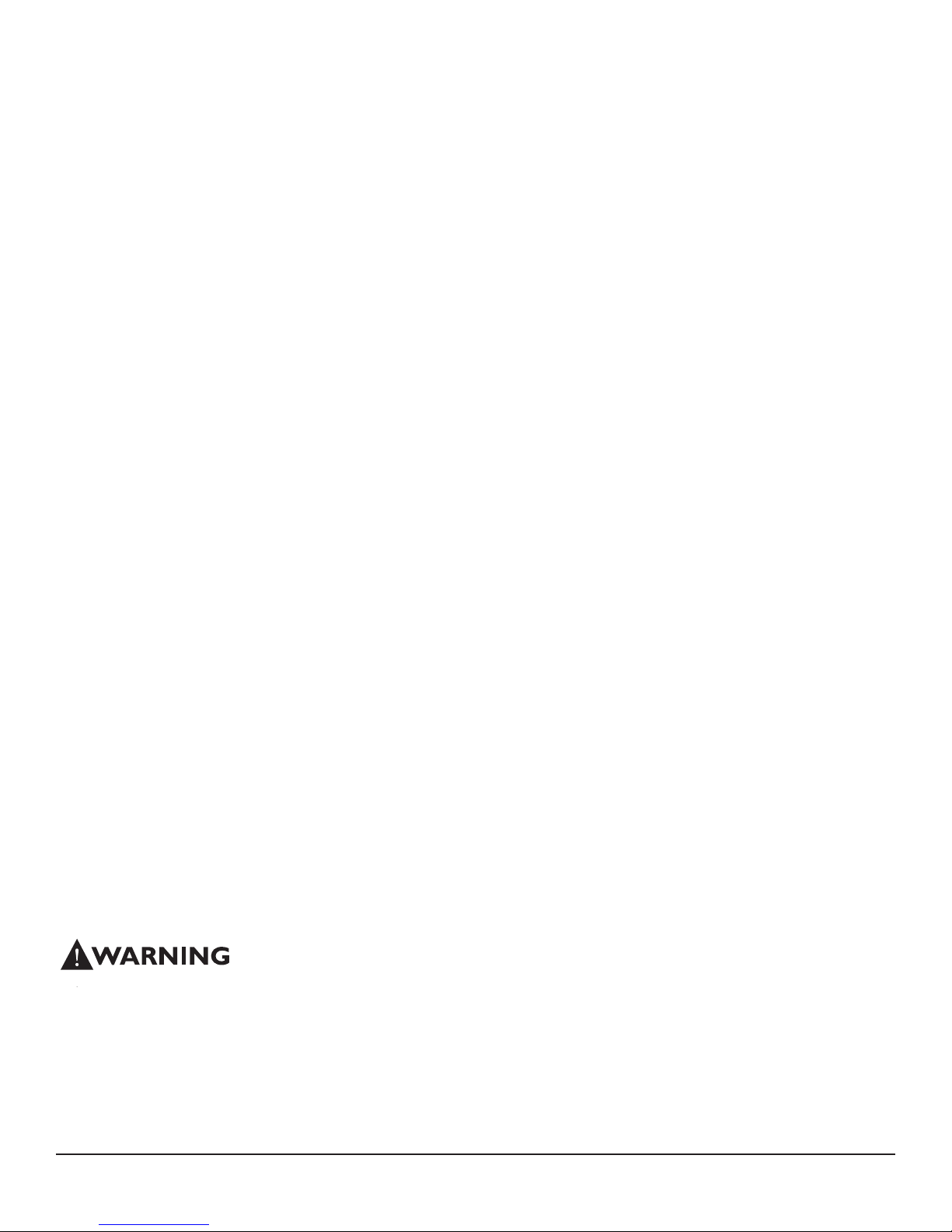
Table of Contents
Introduction ................................................................1
1. Specifications ........................................................2
2. Operation .............................................................2
2.1 Transporting ...................................................2
2.2 Electrical Requirements ..................................2
2.3 Condensate Removal ......................................2
2.4 Ducting ...........................................................2
2.5 Power Switch .................................................3
2.6 Pump Purge Switch .........................................3
2.7 Hour Meter ....................................................3
2.8 Temperature Specific Operation .......................3
2.9 Low Pressure Control ......................................4
3. Maintenance .........................................................4
3.1 Air Filter .........................................................4
3.2 Storage .........................................................4
4. Service .................................................................4
4.1 Technical description ......................................5
4.2 Troubleshooting ..............................................5
4.3 Blower Replacement .......................................6
4.4 Defrost Thermostat and Timer .........................6
4.5 Condensate Pump ..........................................6
4.6 Gravity Drain Option ........................................6
4.7 Relay ..............................................................7
5. Options and Accessories .......................................7
6. Wiring Diagram ....................................................7
7. Service Parts .......................................................8
8. Warranty ..............................................................9
1 Specifications
Part No. 4025900
Power 7.5 amps, 110-120 VAC, Grounded
Water 140 pints/day @ AHAM (80°F, 60%)
Removal
32 gal/day maximum @ saturation
Blower 335 CFM without external ducting
310 CFM @ .15 IWG external static
Operating 33°F min., 125°F max.
Range
Refrigerant 1 lbs., 14 oz. R-22
Charge
Filters
Duct Options Intake – 12” Flex-Duct
Supply – 10” Lay-Flat
Warranty Five years;
1st year 100% of Parts and Labor
2nd–5th year 100% of Parts of sealed
refrigeration system.
Dimensions
Machine Shipping
Width 20.25” 24”
Height 40” 45.25”
Depth 21.375” 25.5”
Weight 138 lb 164 lb
26 gal/day @ saturation
16” x 20” x 2” Pleated Media MERV-11
2 Operation
Serial No. ___________________________
Purchase Date ______/______/_____
Dealer’s Name ___________________________________
Read the operation and maintenance instructions
carefully before using this unit. Proper adherence to these
instructions is essential to obtain maximum benefit from
your Phoenix 200 HT dehumidifier.
• It is designed to be used INDOORS ONLY.
• If used in a wet area, plug it into a GROUND FAULT
NTERRUPTER.
• DO NOT use the Phoenix 200 HT as a bench or table.
• It must always be used in the upright position.
2.1 Transporting
The Phoenix 200 HT must always be upright when
transported by vehicle. It may be tipped onto its handle
and back for loading and moving by hand. The Phoenix
200 HT features a high-impact plastic skid plate which
protects the unit while navigating obstacles such as curbs,
stairways, and while loading into vehicles.
2.2 Electrical Requirements
The Phoenix 200 HT plugs into a common grounded outlet
on a 15 Amp circuit. It draws 7.5 Amps at 80°F, 60% RH.
If used in a wet area, a ground fault interrupter (GFI) is
required. If an extension cord is required, it must have a
minimum of 14 gauge conductors if 25 feet long or less
and 12 gauge conductors if greater than 25 feet long.
2
www.usephoenix.com • sales@thermastor.comToll-Free 1-800-533-7533
2.3 Condensate Removal
The Phoenix 200 HT is equipped with an internal
condensate pump to remove the water that is condensed
during dehumidification. This allows the condensate to be
pumped 30’ with the attached hose. If the condensate
must be pumped more than 20 feet above the unit, a
second pump must be added to relay the condensate. If
the pump fails and the unit must be used before it can be
replaced, the condensate can be drained by gravity.
The air inlet on top and the side outlet must be at least
1 foot from walls and other obstructions to air flow. If the
humid area is very large, dehumidification can be improved
by adding an outlet duct to circulate air to stagnant areas.
2.4 Ducting
A detachable rectangular exhaust collar is supplied to
allow 10” round lay-flat duct to be attached to the Phoenix
200 HT outlet. Lay-flat plastic ducting is available. See
accessories on page 6. To attach ducting to a collar, put
the plastic duct end through the collar center and roll the
duct end outward so that it overlaps the outside of the
collar. The duct and collar may then be quickly attached to
the Phoenix 200 HT by snapping the collar over the four
screws at the blower outlet.
2.5 Power Switch
The power switch (right of hour meter) lights up when
the unit is turned on. The unit will continue to run in
all conditions until the switch is turned off; there is no
dehumidistat. If the unit is going to run for more than 2
hours in an area below 50°F, the defrost timer should be
adjusted to improve performance.
2.6 Purge Switch
Pressing and holding the purge switch (left of hour meter)
will cause the condensate pump to run. This pump
minimizes the water left in the condensate reservoir prior
to moving or storage. Hold the switch in until the flow from
the condensate hose stops.
is directed across the evaporator. This airflow lowers
the refrigerant pressure in the condenser and improves
dehumidifier efficiency. The relative reduction or slowing
of airflow across the evaporator allows more time for the
air temperature to be lowered to the dew point, which
also increased dehumidifier efficiency. These higher
temperatures are often found after the first 24 hours.
See Figure 1 for correct grain control magnet position for
operating in temperatures above 90°F.
Figure 1: Defrost timer and grain control magnet position for
operating in temperatures above 90°F.
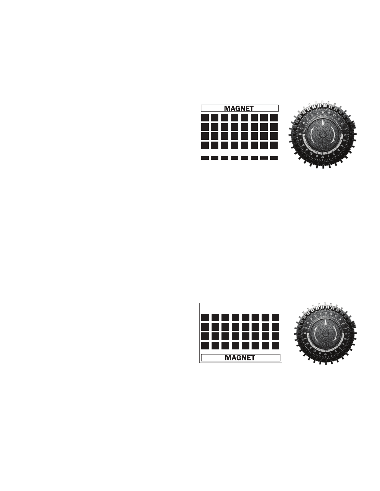
Between 50°F - 90°F - When the Phoenix 200 HT is used
in normal dehumidifier operating temperatures (70°F to
90°F), the grain control magnet should cover the bypass
openings.
This allows increased airflow across the evaporator and
increases performance by increasing the amount of air
that is dehumidified. This temperature range is often
found during the first 24 hours of a drying job. When the
Phoenix 200 HT is used in cooler operating temperatures
(50°F to 70°F), the grain control magnet increases airflow
across the evaporator and reduces frost formation. See
Figure 2 below for correct grain control magnet position for
operating in temperatures from 50°F to 90°F.
2.7 Hour Meter
The digital hour meter measures the cumulative time that
the unit is turned on to tenths of an hour. It stores its
total when the unit is unplugged; the previous total will be
displayed when the unit is next turned on. It resets to zero
after 99,999.9 hours of operation.
2.8 Temperature Specific Operation
Above 90°F - When the Phoenix 200 HT is used in high
temperature conditions (above 90°F), the refrigerant
pressure inside the condenser rises. By removing the
grain control magnet from the bypass openings, additional
airflow is directed over the condenser and less airflow
Figure 2: Defrost timer and grain control magnet position for
operating in temperatures above 50°F to 90°F.
Below 50°F -When the Phoenix 200 HT is used in very cool
operating temperatures (below 50°F), frost will form on
the evaporator coil as it dehumidifies. When enough frost
forms, the defrost thermostat will initiate the timed defrost
cycle. The cycle periodically turns off the compressor while
allowing the blower to run. The grain control magnet should
cover the bypass openings in this operating range because
the increased airflow and static pressure will help defrost
3
www.usephoenix.com • sales@thermastor.comToll-Free 1-800-533-7533
 Loading...