


22

23
Contents
General Safety Information
Major Functions
Recommendations for Use
Mounting and Connecting
1. Using MPS as a DC load switch with deep-discharge protection
1.1 MPS features
1.2 Setting up your MPS as DC load switch with deep-discharge protection
1.3 Installation instruction
1.4 Starting up the Controller
2. Using MPS as PV Charge Controller
2.1 MPS features
2.2 Setting up your MPS as PV Charge Controller (stand-alone mode)
2.3 Installation instruction
2.4 Starting up the Controller
3.Using MPS as Wind/Hydro generator Charge Controller (Diversion control)
3.1 MPS features
3.2 Setting up your MPS as Wind/Hydro Charge Controller (stand-alone mode)
3.3 Installation instruction
3.4 Starting up the Controller
Safety Recommendations
Liability Exclusion
Technical Data
24
25
26
26
26
26
28
29
30
31
32
34
34
36
37
37
38
39
40
41
41
42
EN

With your new MPS Modular Power Switch, you own a state-of-the art device which was developed
according to the latest available technical standards. It comes with a number of outstanding
features, such as:
This manual gives important recommendations for installing, using and programming as well
as remedies in case of problems with the controller. Read it carefully in your own interest
and mind the safety and usage recommendations at the end of this manual.
General Safety Information
24
EN
This manual contains important installation, set up, and safe operating instructions.
Please read the instructions and warnings in this manual carefully before beginning any
installation.
Please do not disassemble or attempt to repair Phocos products. Phocos charge controllers do
not contain user serviceable parts.
Please observe all instructions with regards to external fuses/breakers as indicated.
The information contained in this manual must be observed in its extent. The manual contains
information regarding installation, set up, and operation.
Please read this manual carefully before using the product, and pay special attention to the
safety recommendations in it.
Maintenance and installation notes
When installing or working on the PV system, please disconnect the PV (solar) modules from
the charge controller first, to prevent damages to the charge controller!
Please verify that all cable/wire connections are done properly and well insulated and that
no water or humidity can ingress that is to avoid any bad or loose connections that would
result in excessive heating or further damage.
Please install a fuse or breaker near the battery before installing or adjusting the controller!
12 V, 24 V or 48 V (Automatic Detection)
Low Voltage Disconnect/Load Prioritization
Over-Charge Protection
Choose Regulation Between: Pulse-Width Modulation, Two-Point-Control (or bank switching
with MCU)
Diversion Control (dump loads) for Wind and Hydro Power Systems
Flexible grounding (negative or positive)
DIN Rail Mounting (possible to use with IP65 cabinet)
Five programmable voltage thresholds for load disconnect when used as a stand-alone unit.
More thresholds available when controlled by optional accessory MCU.

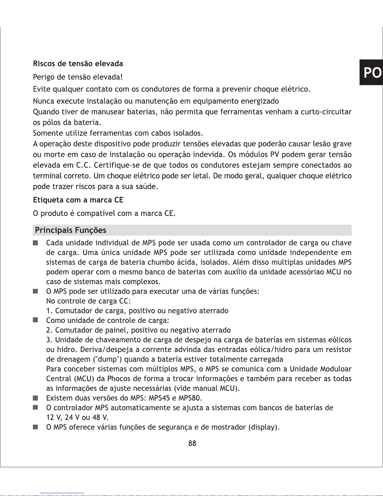
High voltage risks
Never touch any electrical conductors to avoid electrical shock.
Never work on live (energized) electrical equipment.
When working around a battery, do not allow tools to bridge the battery terminals, or short
circuit any part of the battery.
Use only tools with insulated handles.
Operation of this device may produce a high voltage which could cause severe injuries or death
in case of improper installation or operation of the device.
PV modules can generate high DC voltages!
Mains and charging current risks
Make sure the cables are always connected to the correct terminal. An electrical shock can
be lethal. In general, any electric shock can be dangerous to your health.
CE labeling
The product is CE compliant.
Major Functions
Individual MPS units can be used as charge controller or load-controlling switch. A single
MPS unit can be used as an independent device within off-grid battery charging systems
for lead acid batteries. Also, multiple MPS units can operate within the same battery-based
system with the help of optional accessory MCU for more complex system designs.
MPS can be used to perform one of several tasks:
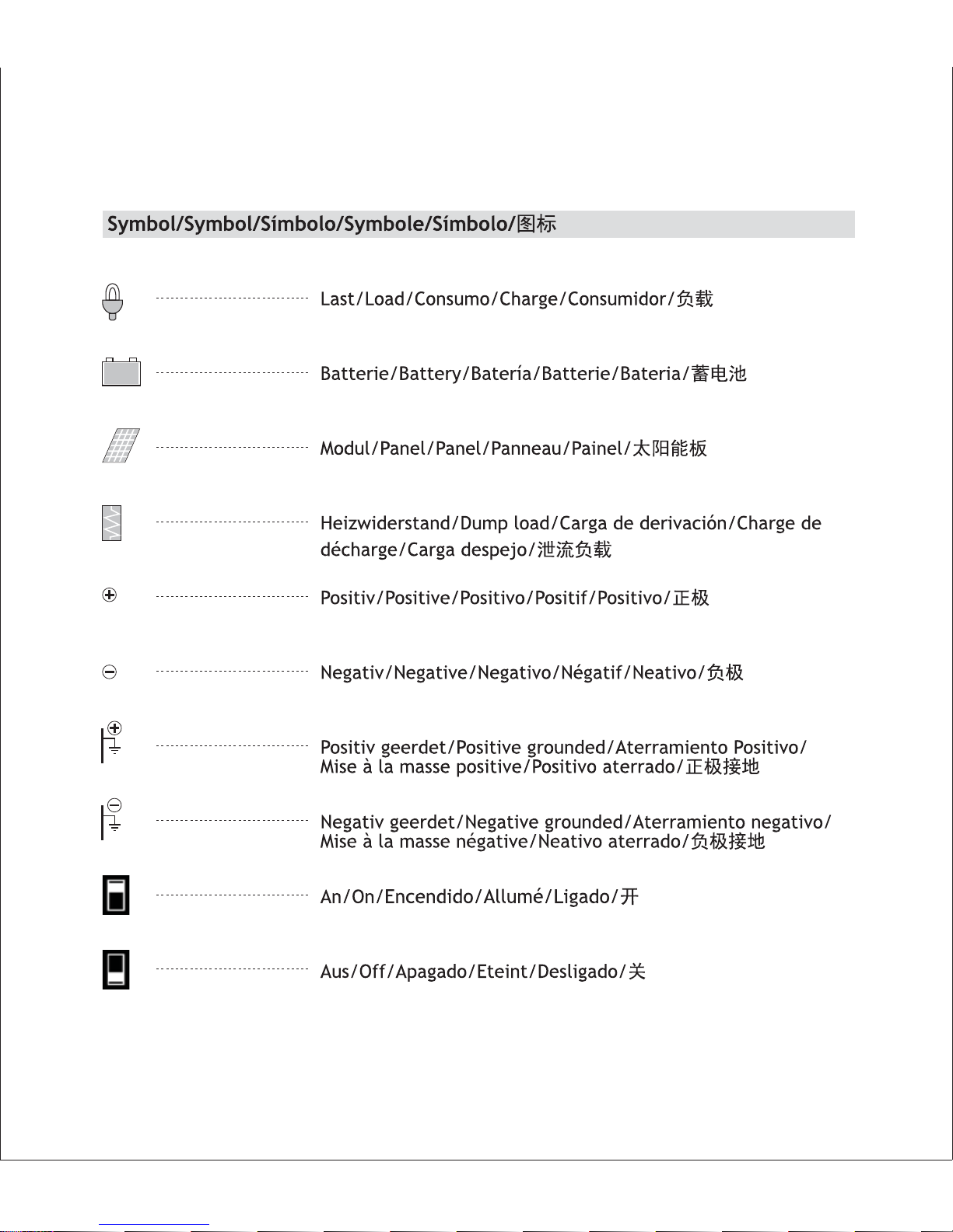
DC Load Control:
1. Load switch, positive/negative grounded
Battery Charge Control:
2. Panel switch, positive/negative grounded
3. Diversion load switch for battery charging via wind/hydro inputs. Diverts current from
wind/hydro inputs to a dump load resistor when battery is fully charged.
To construct systems using multiple MPS units, MPS has the ability to communicate with
Phocos' Modular Central Unit (MCU) in order to exchange system information, to program
and to receive all necessary system settings (see MCU manual).
There are two available MPS versions: MPS45 and MPS80.
The MPS controller automatically detects the nominal system voltage when connected to
a 12 V, 24 V or 48 V battery bank.
The MPS has a number of safety and display functions.
25
EN

Mounting and Connecting
MPS is intended for indoor use only. Protect it from direct sunlight and place it in a dry
environment. Never install it in rooms with elevated humidity (bathrooms, etc.).
The controller warms up during operation and should therefore be installed on a non
flammable surface only.
Using MPS as a DC load switch for deep discharge protection (Chapter 1, page 24)
Using MPS as a photovoltaic charge controller (Chapter 2, page 29 )
Using MPS as a wind-/hydro generator charge controller (diversion control)(Chapter 3, page 35)
There are 3 different possible applications for using the MPS as stand-alone unit:
This chapter describes how to set up and install your MPS as stand-alone DC load switch with
deep-discharge protection and the available features when performing this duty.
As a stand-alone unit, MPS provides you five voltage thresholds (LVD1 to LVD5) for disconnecting
DC loads when battery state of charge becomes low.
Several independent MPS units can also operate in the same system, providing up to the nominal
current of each individual MPS unit to several different loads.
Do not use multiple MPS units in parallel to provide higher current to a single load in standalone systems without the use of optional accessory MCU. This is only possible by using MPS
together with MCU (see MCU manual).
1.1 MPS features:
Battery System Voltage Detection
MPS can be used in 12 V, 24 V, 48 V battery systems. The nominal system voltage is detected
automatically when connected to the battery bank.
1. Using MPS as a DC Load Switch with Deep-Discharge Protection
Recommendations for Use
The MPS controller warms up during normal operation. If there is insufficient ventilation
(e.g. in a cabinet), the controller has built-in overheating protection.
The MPS controller does not require any maintenance or service. Remove any dust with a
dry tissue.
It is important that the battery bank achieves fully charged status frequently (at least once
per month). Otherwise the battery may be permanently damaged.
A battery can only be fully charged if the average energy consumption of all loads is clearly
less than the average charging energy.
26
EN

After cut-off, the load will be reconnected automatically after one minute.
System Grounding:
MPS can control loads in positive and negative grounded systems. Grounding is selected by
wiring of your MPS, see details in chapter 1.3.2.
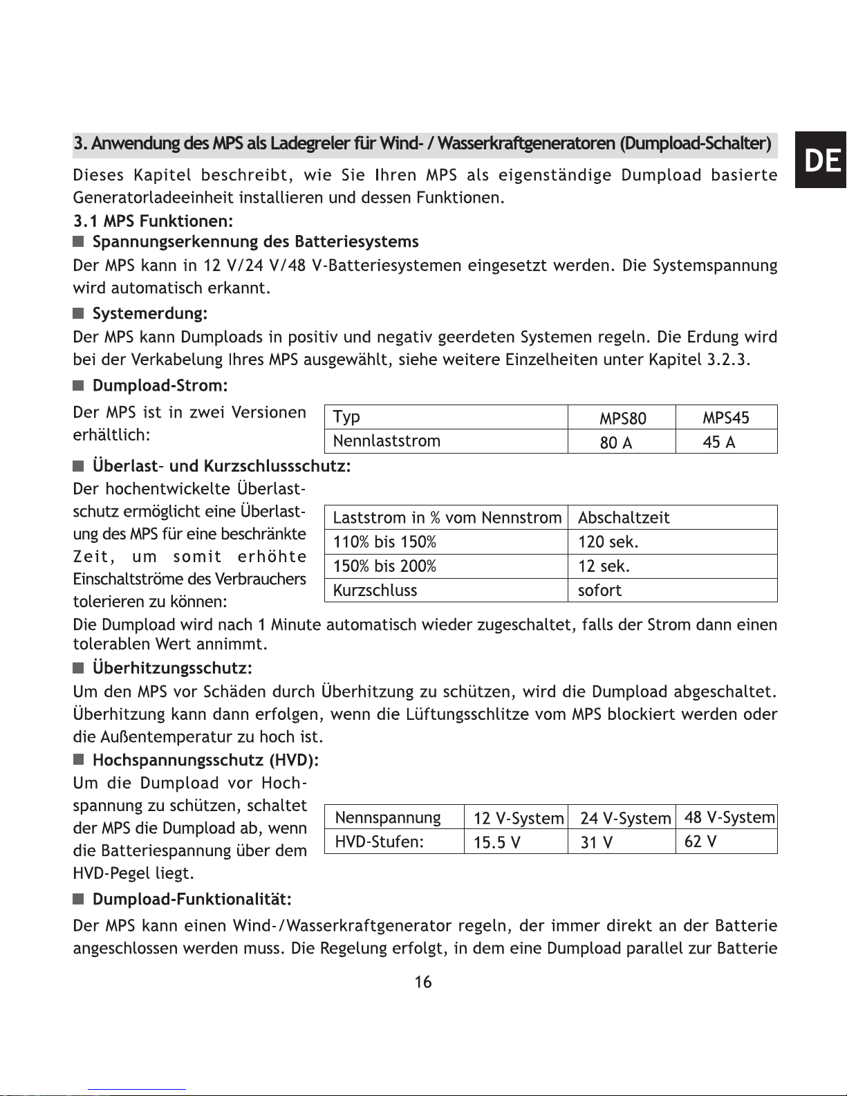
Load Current:
MPS is available in two versions:
Overtemperature Protection:
To protect MPS from damage due to overheating, MPS will switch off the load until cooled
down. Overheating can occur if MPS's ventilation grill is blocked or if the ambient temperature is
too high.
High Voltage Protection (HVD):
To protect the load from high
voltage, MPS will disconnect the
load if battery voltage is higher
than HVD level.
Nominal voltage
HVD level
12 V system
15.5 V
24 V system
31.0 V
48 V system
62 V
Deep Discharge Protection (LVD):
MPS provides five deep discharge
protection thresholds. This
allows you to select the load
disconnect level according to
your system requirements.
Nominal
voltage
LVD-level
12 V system
24 V system
48 V system
Type
Nominal load current
MPS80
80 A
MPS45
45 A
Overload and Short Circuit Protection:
MPS advanced overload protection allows overload for a limited
time, to enable inrush current
when switching on loads:
Load current in % of nominal current
110% to 150%
150% to 200%
Short circuit
Time to switch off
120 sec
12 sec
Immediately
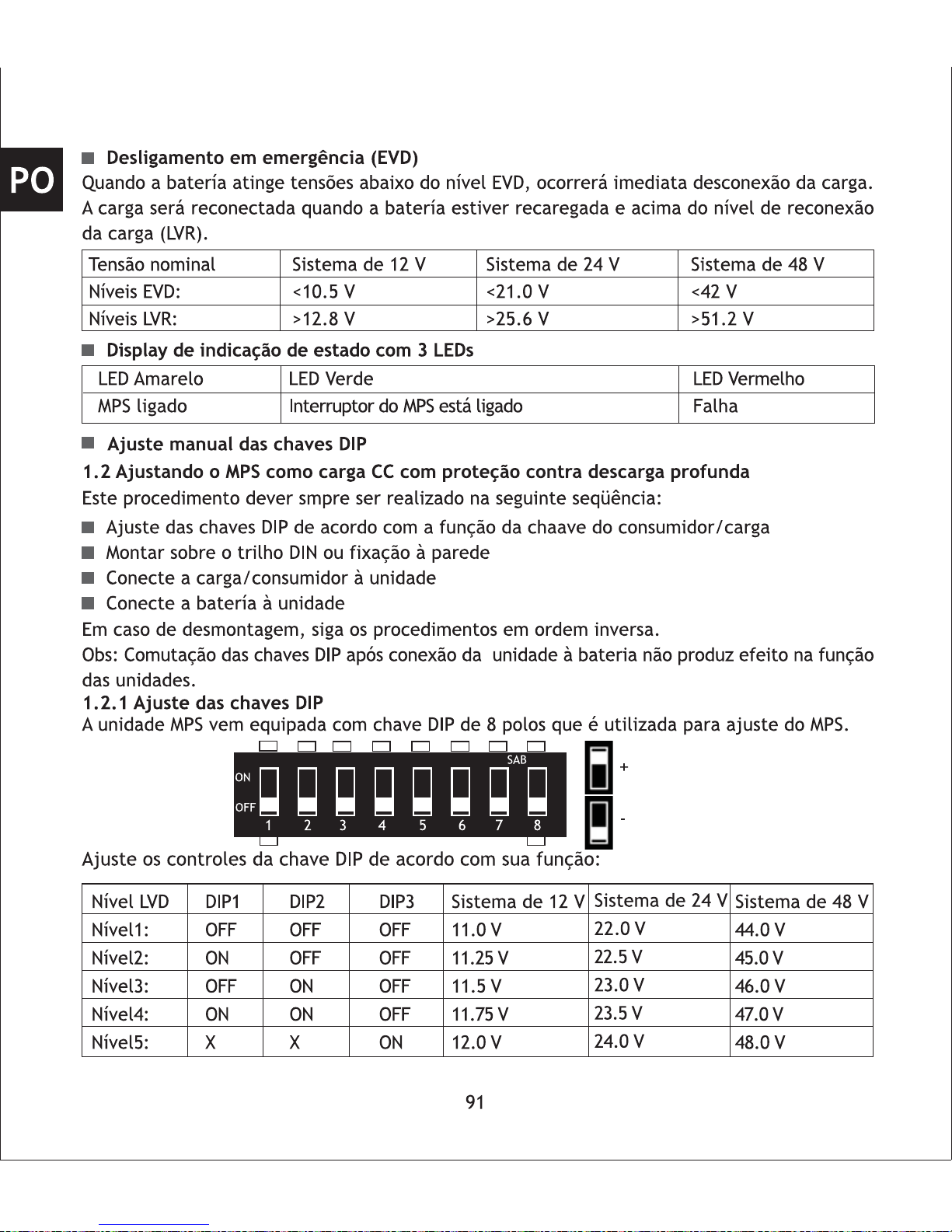
Emergency Switch Off (EVD)
When battery voltage drops down
below EVD level, the load will
be switched off immediately.
The load will be reconnected
after battery is recharged and
battery voltage is above the load
reconnect level (LVR).
11.0 V
11.25 V
11.5 V
11.75 V
12.0 V
22.0 V
22.5 V
23.0 V
23.5 V
24.0 V
44.0 V
45.0 V
46.0 V
47.0 V
48.0 V
Level 1
Level 2
Level 3
Level 4
Level 5
27
Nominal voltage
EVD level
LVR level
12 V system
<10.5 V
>12.8 V
24 V system
<21.0 V
>25.6 V
48 V system
<42 V
>51.2 V
EN

1.2 Setting up your MPS as a DC load switch with deep-discharge protection
Please be sure to always follow this procedure in the following sequence:
Set the DIP switches according to the load switch function
Mount MPS on DIN rail or wall
Connect the load wiring to the unit with proper polarity.
Connect the battery wiring to the unit with proper polarity.
When disassembling perform the installation sequence in reverse order.
Note: Changes to DIP switches after connecting the unit to the battery do not affect the function
of the unit.
1.2.1 Set-up DIP Switches
The MPS comes with an eight
pole DIP-switch, which can be
used to set up your MPS.
Adjust the DIP switch settings according to load switch function:
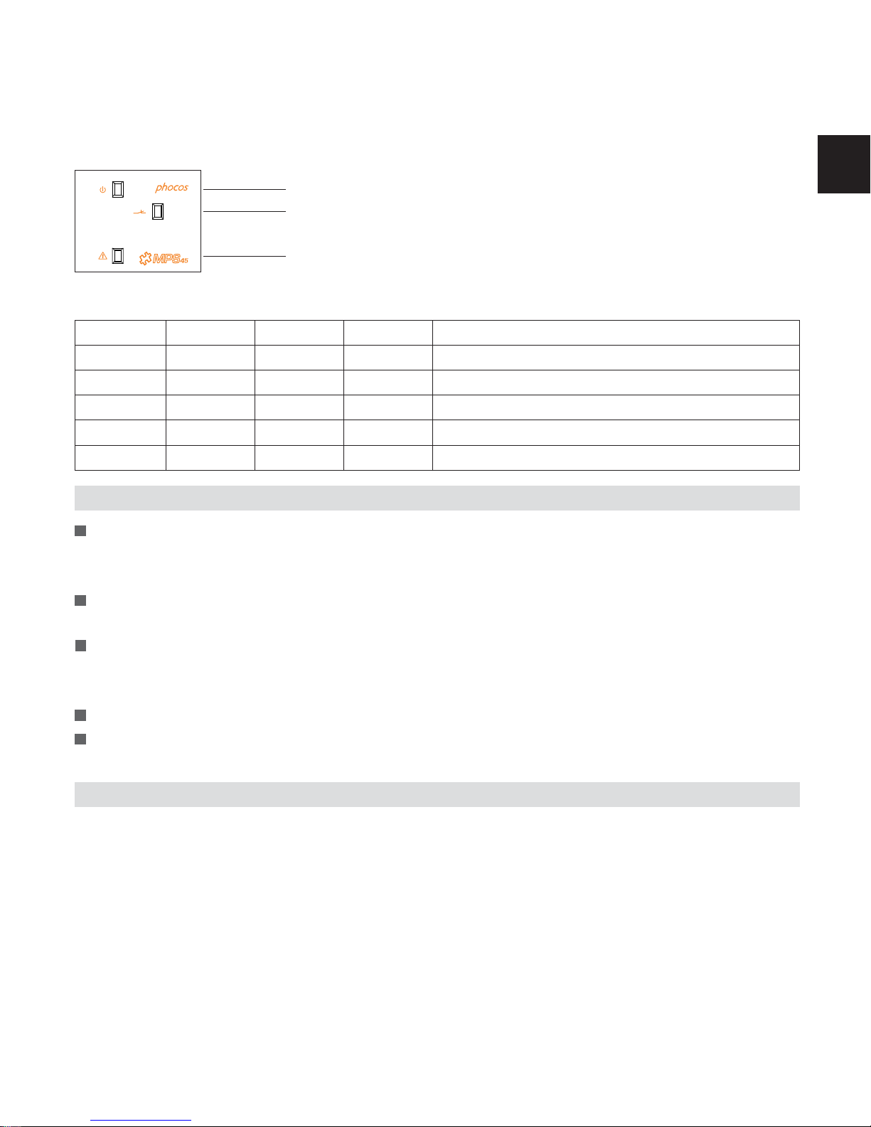
Three-LED Status Display
Manual Setting by DIP Switches
28
Yellow LED
MPS on
Green LED
MPS power switch is on
Red LED
Failure
Setting
OFF
X
X
OFF
X
Function
Activates MPS as load switch/deep discharge protection
Unused
Unused
Stand-alone function
Unused
DIP NO.
DIP 8
DIP 7
DIP 6
DIP 5
DIP 4
12 V system
11.0 V
11.25 V
11.5 V
11.75 V
12.0 V
DIP1
OFF
ON
OFF
ON
X
DIP2
OFF
OFF
ON
ON
X
DIP3
OFF
OFF
OFF
OFF
ON
EN
LVD level
Level1
Level2
Level3
Level4
Level5
24 V system
22.0 V
22.5 V
23.0 V
23.5 V
24.0 V
48 V system
44.0 V
45.0 V
46.0 V
47.0 V
48.0 V
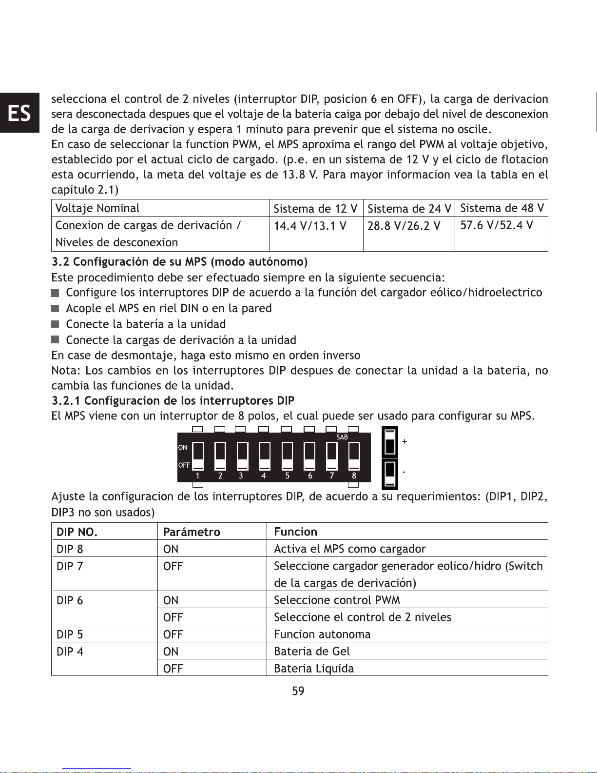
+
-
12345678
SAB
ON
OFF
1 2
3
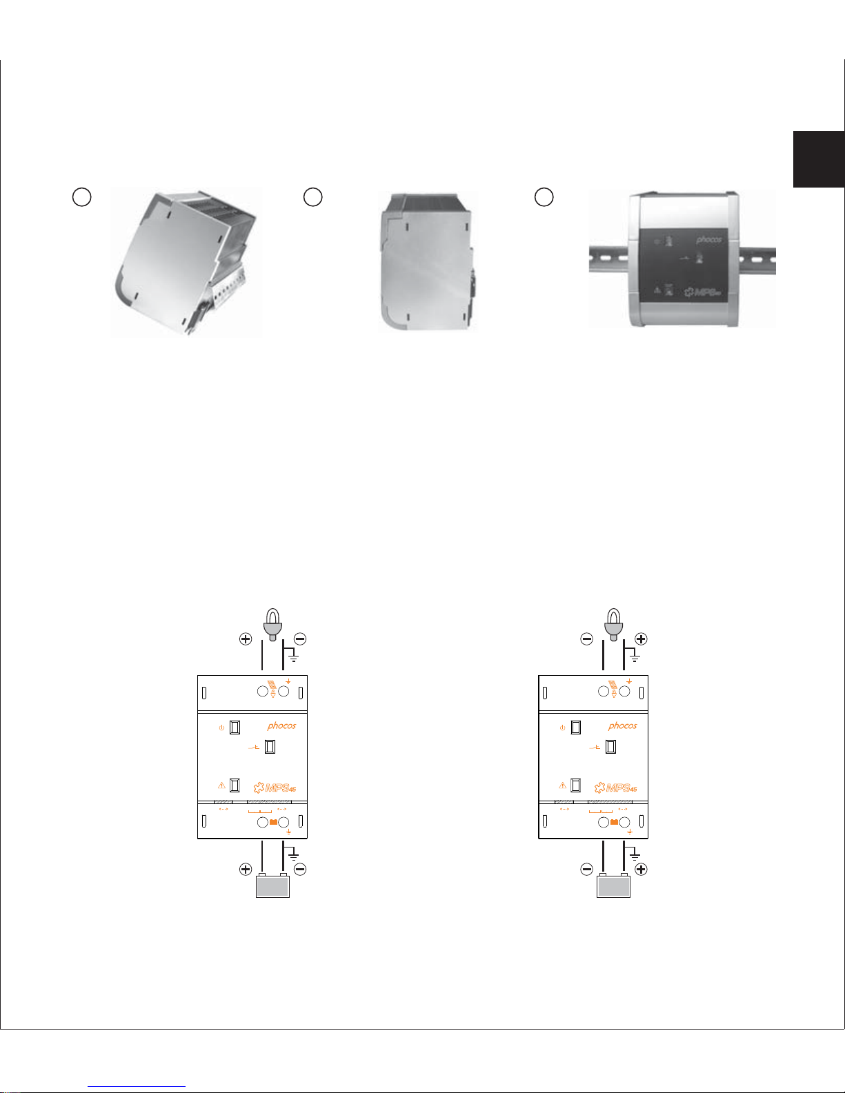
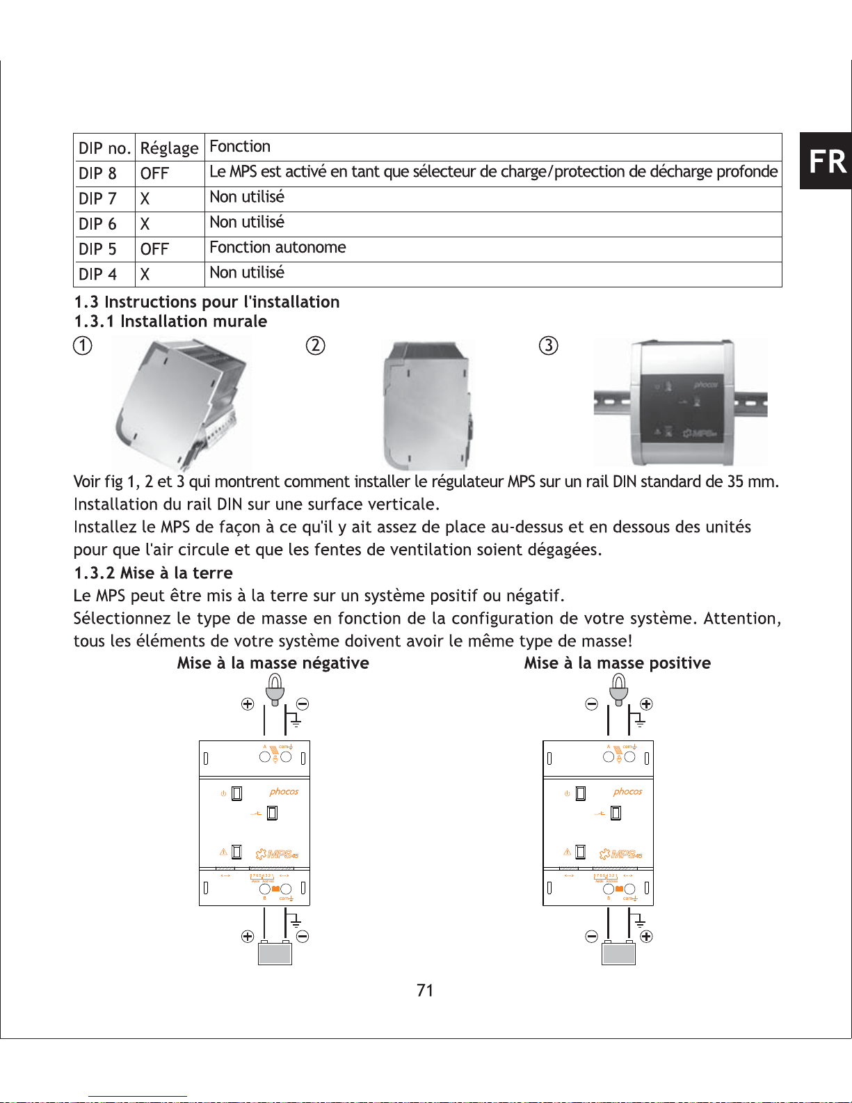
Please see fig 1, 2 and 3 which shows how to install the MPS controller on a standard 35 mm
DIN Rail.
Mount DIN Rail onto a vertical surface.
Mount MPS in a manner that ensures there is enough space above and below the unit to ensure
vertical air flow through the ventilation grill.
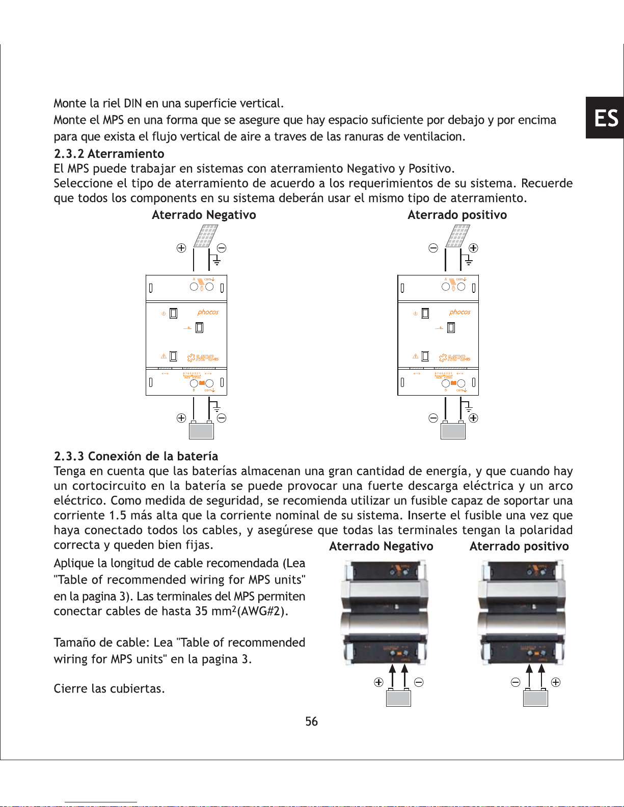
1.3.2 Grounding
MPS can work in negative or positive grounded systems.
Select the type of grounding according your system requirements. Respect that all components
in your system should use the same type of grounding!
1.3 Installation Instruction
1.3.1 Wall Mounting
Positive groundedNegative grounded
29
com
comAB
87654321
AddressMode
com
comAB
87654321
AddressMode
EN

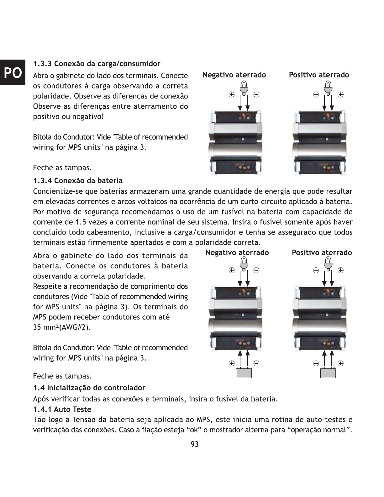
1.3.3 Connecting the Load
Negative grounded Positive grounded
Open the cover at the load terminals. Connect
the wires leading to the load with the correct
polarity. Respect the appropriate wiring for
negative and positive grounded systems!
Wire size: See "Table of recommended wiring
for MPS units" on page 3.
Close the wire cover.
1.3.4 Connecting the Battery
Respect that batteries store a substantial amount of energy which can produce high current
and electric arc when a short circuit is applied to the battery. It is recommended to install a
battery fuse which must be able to carry currents of 1.5 times of your nominal system current
for safety considerations. Insert the fuse after you have connected all wires including the load
and make sure that all terminals are fixed tightly with proper polarity.
Negative grounded Positive grounded
Open the cover on the battery terminal side.
Connect the wires leading to the battery with
the proper polarity.
Mind the recommended wire length (See "Table
of recommended wiring for MPS units" on page
3). MPS terminals can connect up to 35 mm
2
wire (AWG#2).
Wire size: See "Table of recommended wiring
for MPS units" on page 3.
Close the wire cover.
1.4 Starting up the Controller
After double-checking all wires and terminals insert battery fuse.
1.4.1 Self test
As soon as battery voltage is applied to MPS, the unit begins a self test routine and wiringcheck. If system passes wiring-check, the LED display changes to "normal operation".
30
EN

2. Using MPS as PV Charge Controller
This chapter describes how to set up and install your MPS as an independent PV charge controller
and the available features when performing this duty.
Several independent MPS units can be used as PV charge controllers in your system increasing
the available charge current to the battery bank.
Do not operate several MPS in parallel to one solar-array. Each MPS unit should only be used
with a solar-array that produces equal or less than the nominal current rating of your MPS
unit at peak conditions. In stand-alone mode (without MCU), up to three MPS units can be
operated as PV charge controllers connected to the same battery bank.
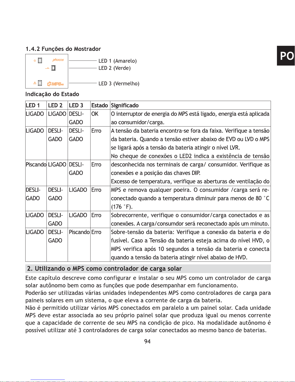
1.4.2 Display Functions
Status indication
LED 1
ON
ON
Flash
OFF
ON
ON
LED 2
ON
OFF
ON
OFF
OFF
OFF
LED 3
OFF
OFF
OFF
ON
ON
Flash
Status
OK
Error
Error
Error
Error
Error
Meaning
MPS power switch is on (active), power applied to connect
load.
Battery voltage out of range. MPS switched off. Check
battery voltage when voltage is below EVD or LVD. MPS
switches on after battery voltage reaches LVR level.
On wiring check LED 2 indicates an unuaual voltage is
on the load output. Check load wiring and DIP settings.
Overtemperature, check ventilation grill of your MPS and
remove any visible dust. Load will be reconnected after
temperature is lower than 80°C (176 F).
Overcurrent, check your connected load and wiring. Load
will be reconnected after one minute.
Battery over-voltage: check battery, fuse and battery wiring.
If battery voltage is higher than HVD-level MPS checks
battery voltage after 10 seconds and switches on, when
battery voltage is lower than HVD-level.
LED 3 (Red)
LED 1 (Yellow)
LED 2 (Green)
31
EN

2.1 MPS features:
Battery System Voltage Detection
MPS can be used in 12 V, 24 V, or 48 V battery systems. The nominal system voltage is detected
automatically when connected to the battery bank.
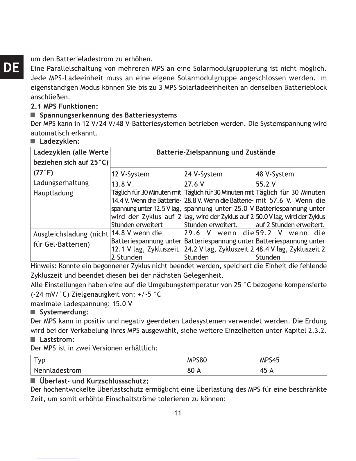
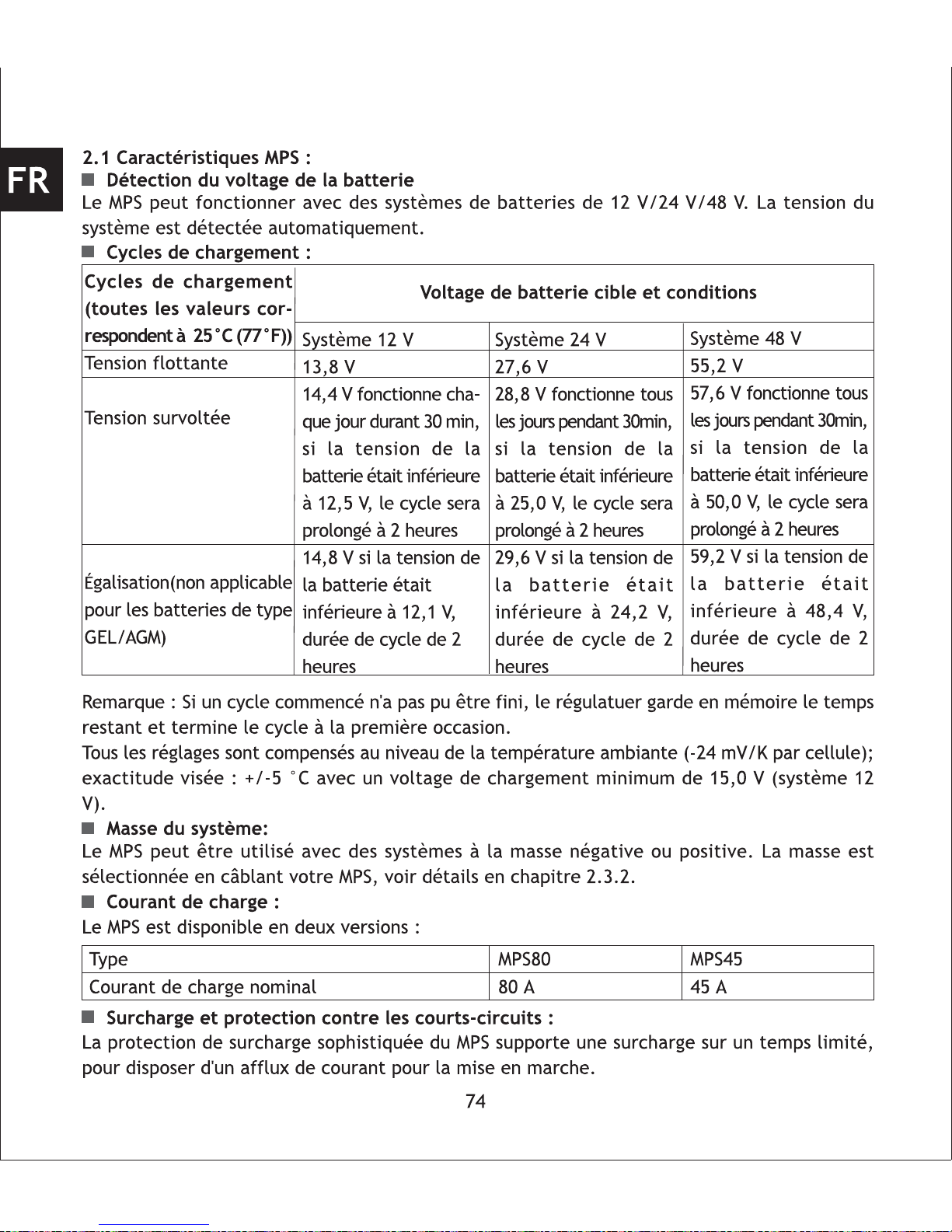
Charge Cycles:
Note: If a started cycle could not be finished, the controller stores the lacking cycle time and
uses the next chance to finish.
All settings are ambient temperature compensated (-24 mV/K per cell) target accuracy: +/-5°C,
maximum charging voltage 15.0 V (12V system).
System Grounding:
MPS can be used in positive and negative grounded charging systems. Grounding is selected
by wiring of your MPS, see details in chapter 2.3.2.
Charging Current:
MPS80
80 A
MPS45
45 A
MPS is available in two versions:
Overload and Short Circuit Protection:
MPS advanced overload protection allows overload for a limited time, to enable inrush current
when switching on:
Type
Nominal charging current
32
12 V system
13.8 V
14.4 V (runs every day
for 30 min, if battery was
below 12.5 V cycle will
be extended to 2 hours)
14.8 V (if battery was
below 12.1 V cycle
duration 2 hours)
Charging Cycles [all values
correspond to 25°C (77 F)
operation temperature]
Float
Boost
Equalize (not applied for
GEL/AGM type batteries)
Battery Target Voltage and Conditions
24 V system
27.6 V
28.8 V (runs every day
for 30 min, if battery was
below 25.0 V cycle will
be extended to 2 hours)
29.6 V (if battery was
below 24.2 V cycle
duration 2 hours)
48 V system
55.2 V
57.6 V (runs every day
for 30 min, if battery was
below 50.0 V cycle will
be extended to 2 hours)
59.2 V (if battery was
below 48.4 V cycle
duration 2 hours)
EN

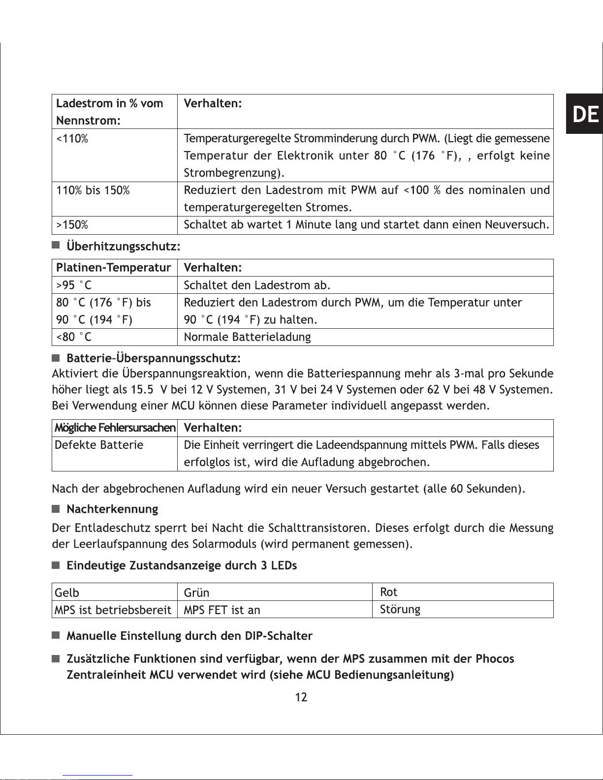
Battery Over-Voltage Protection:
Activates over-voltage procedure if battery voltage is more than three times per second higher
than 15.5 V in 12 V systems, 31 V in 24 V systems or 62 V in 48 V systems. Optional accessory
MCU can adjust this parameter.
Charge current in %
of nominal current
Action
Temperature-controlled current reduction by PWM. (If power electronic
temperature is below 80 °C (176 F), no limitation of current occurs).
Charge current reduction by PWM to < 100 % and temperature controlled
current reduction.
Switches off, waits for one minute and tries again
Overtemperature Protection:
Possible failure reason
Defective battery
Action
Reduces charge voltage. If this does not correct the issue, charging
stops and LED indicates a failure(tries charging again one minute later)
If after charging stopped failure disappears, MPS starts a new procedure.
Night Detection
Three-LED Status Display
Manual Setting by DIP Switches
Additional features available if MPS is used together with Phocos Modular Control Unit
MCU (see MCU manual )
Discharge current protection at night by FET switch off.
Panel open circuit voltage measured during day and night.
33
<110%
110% to 150%
>150%
PCB temperature Action
Switches off charge current
Reduces charge current by applying PWM to keep temperature below
90 °C (194 F)
Normal charge function
>95 °C
80 °C (176 F) to
90 °C (194 F)
< 80 °C
Yellow LED
MPS ready
Green LED
MPS FET is on
Red LED
Failure
EN

2.2 Setting up your MPS as PV Charge Controller (stand-alone mode)
Please be sure to always follow this procedure in the following sequence:
Set the DIP switches according to the PV charge controller function
Mount MPS on DIN Rail or wall
Connect the battery to the unit with proper polarity
Connect the solar array to the unit
When disassembling, perform the installation sequence in reverse order.
Note: Changes to DIP switches after connecting the unit to the battery do not affect the function
of the unit.
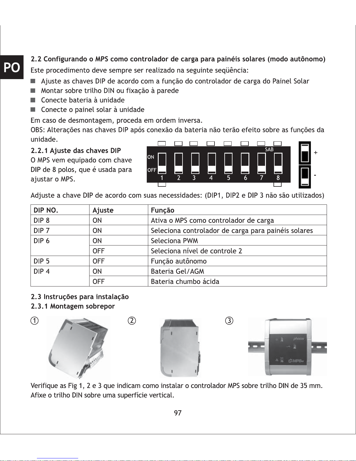
2.2.1 Setup DIP Switches
The MPS comes with an eight pole
DIP-switch, which can be used to
set up your MPS.
Setting
ON
ON
ON
OFF
OFF
ON
OFF
Function
Activates MPS as charge controller
Activates MPS as PV charge controller
Activates PWM
Activates two-point control
Stand-alone function
Gel/AGM battery
Liquid lead acid battery
DIP NO.
DIP 8
DIP 7
DIP 6
DIP 5
DIP 4
2.3 Installation Instruction
2.3.1 Wall Mounting
Please see fig 1, 2 and 3 showing how to install the MPS controller on a standard 35 mm DIN Rail.
Mount DIN Rail onto a vertical surface.
Adjust the DIP switch settings according to your requirements: (DIP1,DIP2 and DIP3 are unused)
34
1 2
3
EN
+
-
12345678
SAB
ON
OFF

Mount MPS in a way that ensures there is enough space below and above for the air to vertically
air flow through the ventilation grill.
35
2.3.2 Grounding
MPS can work in negative or positive grounded systems.
Select the type of grounding according your system requirements. Respect that all components
in your system should use the same type of grounding!
Positive groundedNegative grounded
2.3.3 Connecting the Battery
Respect that batteries store a substantial amount of energy which can produce high current
and electric arc when a short circuit is applied to the battery. It is recommended to install a
battery fuse which must be able to carry currents of 1.5 times of your nominal system current
for safety considerations. Insert the fuse after you have connected all wires including the load
and make sure that all terminals are fixed tightly with proper polarity.
Negative grounded Positive grounded
Open the cover on the battery terminals side.
Connect the wires leading to the battery with
the proper polarity.
Mind the recommended wire length (See "Table
of recommended wiring for MPS units" on page
3). MPS terminals can connect up to 35 mm
2
wires (AWG#2).
Wire size: See "Table of recommended wiring
for MPS units" on page 3.
Close the covers.
com
comAB
87654321
AddressMode
com
comAB
87654321
AddressMode
EN

2.4 Starting up the Controller
After double-checking all wires and terminals, insert battery fuse.
2.4.1 Self Test
As soon as battery voltage is applied to MPS, the unit begins a self test routine and wiringcheck. If system passes wiring-check, the LED display changes to "normal operation."
2.4.2 Display Functions
Status indication
Meaning
Battery charging
In PWM mode:
solar-array voltage < battery voltage
On two-point control:
solar-array voltage < battery voltage
In PWM mode: current limited by PWM
Over-current or over-temperature
Negative grounded Positive grounded2.3.4 Connecting Solar-Array
Open the cover at the solar-array terminals.
Connect the wires leading to the solar-array
with the correct polarity. Respect the different
wiring for negative and positive grounded
systems!
Wire size: See "Table of recommended wiring
for MPS units" on page 3.
Close the covers.
36
LED 1
ON
ON
ON
OFF
LED 2
ON
OFF
FLASH
OFF
LED 3
OFF
OFF
OFF
ON
Status
OK
Error
LED 3 (Red)
LED 1 (Yellow)
LED 2 (Green)
EN

3.Using MPS as Wind/Hydro Generator Charge Controller (Diversion Control)
This chapter describes the available features and how to set up and install your MPS as dumpload
switch for diversion control in stand-alone mode.
3.1 MPS Features:
Battery System Voltage Detection
MPS can be used in 12 V, 24 V, or 48 V battery systems. The nominal system voltage is detected
automatically when connected to the battery bank.
System Grounding:
MPS can control diversion loads in positive and negative grounded systems. Grounding is selected
by wiring of your MPS, see details in chapter 3.3.2.
Diversion Load Current:
MPS is available in two versions:
Overload and Short-Circuit Protection:
Diversion load will be reconnected automatically after one minute.
Overtemperature Protection:
To protect MPS from overheating and damage due to overtemperature, MPS will switch off
the diversion load. Overheating can happen if MPS's ventilation grill is blocked or ambient
temperature is too high.
High Voltage Protection (HVD):
To protect the diversion load from
high voltage, MPS will disconnect
the diversion load if battery
voltage is higher than HVD level.
Diversion Load Funcionality:
MPS can control a wind/hydro generator input, which always has to be directly connected to
the battery. This is done by switching a diversion load in parallel to the battery if the battery
37
Type
Nominal load current
MPS80
80 A
MPS45
45 A
MPS advanced overload protection
allows overload for a limited time,
to enable inrush current when
switching on loads:
Load current in % of nominal current
110% to 150%
150% to 200%
Short circuit
Time to switch off
120 sec
12 sec
Immediately
Nominal voltage
HVD level
12 V system
15.5 V
24 V system
31.0 V
48 V system
62.0 V
EN

3.2 Setting up your MPS as Wind/Hydro Charge Controller (stand-alone mode)
Please be sure to always follow this procedure in the following sequence:
Set the DIP switches according to the wind/hydro charge controller function
Mount MPS on DIN Rail or wall
Connect the battery to the unit
Connect the diversion load to the unit
When disassembling, perform the installation sequence in reverse order.
Note: Changes to DIP switches after connecting the unit to the battery do not affect the function
of the unit.
3.2.1 Setup DIP Switches
The MPS comes with an eight pole DIP-switch, which can be used to set up your MPS.
Adjust the DIP switch settings according to your requirements:(DIP1,DIP2 and DIP3 are unused)
voltage rises over the diversion load connect voltage. If two-point control is selected (DIP switch
6 OFF), the diversion load will be switched off after the battery voltage drops below the
diversion load disconnect level and pauses one minute to prevent the system from oscillation.
When PWM function is selected, the MPS approximates the PWM range to the actual running
charge cycle target voltage ( e.g. in a 12 V system and float cycle is running -> target voltage
is 13.8 V. For further information see the table in chapter 2.1)
38
Nominal voltage
Diversion load connect/disconnect level
12 V system
14.4 V/13.1 V
24 V system
28.8 V/26.2 V
48 V system
57.6 V/52.4 V
Setting
ON
OFF
ON
OFF
OFF
ON
OFF
Function
Activates MPS as charger
Activates wind/hydro charge controller (Diversion control)
Activates PWM control
Activates two-point control
Stand-alone function
Gel/AGM battery
Liquid lead acid battery
DIP NO.
DIP 8
DIP 7
DIP 6
DIP 5
DIP 4
EN
+
-
12345678
SAB
ON
OFF

Please see fig .1, 2 and 3 showing how to install the MPS controller on a standard 35 mm DIN Rail.
Mount Din Rail onto a vertical surface.
Mount MPS in a way that ensures there is enough space below and above for the air to vertically
air flow through the ventilation grill.
3.3.3 Connecting the battery
Respect that batteries store a substantial amount of energy which can produce high current
and electric arc when a short circuit is applied to the battery. It is recommended to install a
battery fuse which must be able to carry currents of 1.5 times of your nominal system current
1 2
3
3.3.2 Grounding
MPS can work in negative or positive grounded systems.
Select the type of grounding according to your system requirements. Respect that all components
in your system should use the same type of grounding!
Positive groundedNegative grounded
com
comAB
87654321
AddressMode
com
comAB
87654321
AddressMode
Dump load Dump load
39
EN
3.3 Installation Instruction
3.3.1 Wall Mounting

40
3.3.4 Connecting the Diversion Load
Open the cover at the load terminals. Connect
the wires leading to the diversion load with the
correct polarity. Respect the different wiring
for negative and positive grounded systems.
Wire size: See "Table of recommended wiring
for MPS units" on page 3.
Close the covers.
Positive groundedNegative grounded
3.4 Starting up the Controller
After double-checking of all wires and terminals
insert battery fuse.
3.4.1 Self Test
As soon as battery voltage is applied to MPS, the unit begins a self test routine and wiringcheck. If system passes wiring-check, the LED display changes to "normal operation".
for safety considerations. Insert the fuse after you have connected all wires including the load
and make sure that all terminals are fixed tightly with proper polarity.
Negative grounded Positive grounded
Open the cover on the battery terminal side.
Connect the wires leading to the battery with
the proper polarity.
Mind the recommended wire length (See "Table
of recommended wiring for MPS units" on page
3.). MPS terminals can connect up to 35 mm
2
wire (AWG#2).
Wire size: See "Table of recommended wiring
for MPS units" on page 3.
Close the covers.
Dump
load
Dump
load
EN
Safety Recommendations
Batteries store a large amount of energy. Under all circumstances, never short-circuit a
battery. We recommend connecting a fuse (slow acting type, according to the nominal
controller current) directly to the battery terminal.
Batteries can produce flammable gases. Avoid making sparks, or using fire or any open
flame around the battery. Make sure that the battery room is ventilated.
Avoid touching or short circuiting wires or terminals. Be aware that the voltages on specific
terminals or wires can be as much as 95 V. Use isolated tools, stand on dry ground, and
keep your hands dry.
Keep children away from batteries and the MPS unit.
Please observe the safety recommendations of the battery manufacturer. If in doubt, consult
your dealer or installer.
Liability Exclusion
The manufacturer shall not be liable for damages, especially on the battery, caused by use
other than as intended or as mentioned in this manual, or if the recommendations of the battery
manufacturer are neglected. The manufacturer shall not be liable if there has been service
or repair carried out by any unauthorized person, unusual use, incorrect installation, or poor
system design.
Opening the case voids the warranty.
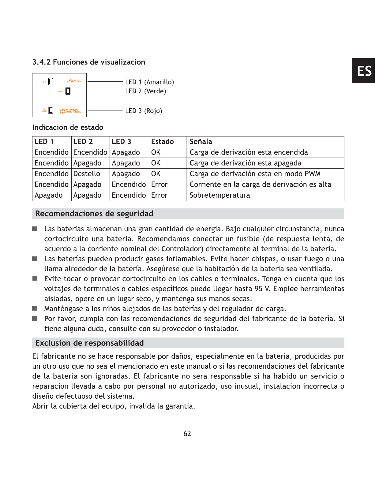
3.4.2 Display Functions
Status indication
Meaning
Diversion load is switched on
Diversion load is switched off
Diversion load is in PWM mode
Diversion load current too high
Over-temperature
LED 1
ON
ON
ON
ON
OFF
LED 2
ON
OFF
FLASH
OFF
OFF
LED 3
OFF
OFF
OFF
ON
ON
Status
OK
OK
OK
Error
Error
LED 3 (Red)
LED 1 (Yellow)
LED 2 (Green)
41
EN

Technical Data
12 V / 24 V / 48 V
MPS45: 45 A
MPS80: 80 A
30V in 12V system
50V in 24V system
95V in 48V system
<6 mA
-25 °C to + 50 °C
109 mm x 150 mm x 112 mm
MPS45: 1007 g
MPS80: 1100 g
IP 22
Nominal voltage
Max. current
Max. panel voltage
Self power consumption
Ambient temperature range
Dimensions
Weight
Case protection
RoHS
ISO9001
Subject to change without notice.
Version: 20140110
Made in one of the following countries:
China - Germany
Phocos AG - Germany
www.phocos.com
42
EN


 Loading...