

Solar-Laderegler CML05-2, CML08-2, CML10-2, CML15-2, CML20
Bedienungsanleitung Deutsch, Seite 1
Sehr geehrter Kunde,
wir bedanken uns herzlich für den Kauf eines Phocos Produktes. Mit Ihrem neuen
C
ML Regler steht Ihnen ein nach dem neuesten Stand der Technik entwickeltes Gerät
z
ur Verfügung, das sich durch besondere Features auszeichnet, wie beispielsweise:
Eindeutige, leicht lesbare Anzeige des Ladezustandes
Akustisches Signal bei Ladezustands-Änderung
Tiefentladeschutz ladezustands- oder spannungsgesteuert
16 mm² Anschlussklemmen
Vollständiger elektronischer Schutz
D
iese Anleitung gibt Ihnen Hinweise zur Installation, zum Betrieb, zur Einstellung und
zur Fehlerbehebung. Lesen Sie sie im eigenen Interesse sorgfältig durch. Beachten Sie
bitte unbedingt die Sicherheits- und Verwendungshinweise am Ende dieser Anleitung.
Funktionsbeschreibung
Der Regler dient dem Schutz des Akkumulators vor Überladung durch den Solar-
generator und Tiefentladung durch die Verbraucher. Die Ladung erfolgt durch eine
m
ehrstufige Ladecharakteristik, die zusätzlich temperaturkompensiert ist, um eine
o
ptimale Batterieladung zu erzielen.
Der Regler erkennt selbständig die Batteriespannung und stellt sich automatisch auf
12V oder 24V Betrieb ein.
Der Regler besitzt eine Reihe von Schutz- und Anzeigefunktionen.
Montage und Anschluss
D
as Gerät ist nur für die Anwendung im Innenbereich geeignet. Das Gerät muss vor
Witterungseinflüssen wie direkter Sonneneinstrahlung oder Nässe geschützt werden.
Der Regler darf nicht in Feuchträumen wie z.B. Bädern montiert werden.
Der Regler misst zur Bestimmung der Ladespannung die Temperatur. Regler und
Batterie müssen im selben Raum untergebracht werden.
Da sich der Regler im Betrieb erwärmen kann, muss er auf einem nicht brennbaren
Untergrund montiert werden.
HINWEIS: Schließen Sie den Regler in jedem Fall in der nachfolgend angegebenen
Reihenfolge an, um Anschlussfehler zu vermeiden.
1
Befestigen Sie den Regler mit für den Untergrund geeigneten
Schrauben (Schaft-Durchmesser 4 mm, Kopfdurchmesser max.
8 mm, kein Senkkopf) an der vorgesehen Stelle. Beachten Sie,
d
ass die Schrauben auch die Kräfte der Anschlusskabel aufnehmen müssen.
Achten Sie darauf, dass die seitlichen Belüftungsschlitze frei sind.
Alternativ kann der Regler mit einer als Zubehör erhältlichen Montageplatte (CX-DR2
)
auf 35 mm DIN Hutschienen montiert werden. Legen Sie den Regler dazu auf die
Montageplatte und schrauben Sie ihn mit den beiden mit der Montageplatte mitgelieferten Schrauben fest.
2
Schließen Sie die Zuleitungen zur Batterie polrichtig an. Um
spannungsfrei zu arbeiten, schließ
en Sie die Kabel zuerst an den
Regler, dann an die Batterie an. Achten Sie auf die Zuleitungslänge (mind 30 bis max. 100 cm) und die Kabelquerschnitte:
CML05: mind 2,5 mm²
CLM08: mind 4 mm²
CML10: mind 6 mm²
CML15, CML20: mind 10 mm²
Verpolter Anschluss wird akustisch signalisiert.
WARNUNG: Falls die Batterie verpolt angeschlossen wurde, gibt der Regler an den
Lastklemmen ebenfalls eine verpolte Spannung ab. Schließen Sie in diesem Zustand
keinesfalls Verbraucher an!
HINWEIS: Beachten Sie auch die Hinweise des Batterieherstellers. Unmittelbar an der
Batterie sollte eine Schmelz-Sicherung angebracht werden, um eventuelle Kurzschlüsse
in den Batterieleitungen abzusichern. Die Sicherung muss dem Nennstrom des Ladereglers entsprechen:
CML05: 20A, CML08: 20A, CML10: 30A, CML15: 30A, CML20: 40A
3
Schließen Sie die Zuleitungen zum Solargenerator polrichtig an.
Um spannungsfrei zu arbeiten, s
chließen Sie die Kabel zuerst an
den Regler, dann an den Solargenerator an. Achten Sie auf die
Kabelquerschnitte:
CML05: mind 2,5 mm²
CLM08: mind 4 mm²
CML10: mind 6 mm²
CML15, CML20: mind 10 mm²
HINWEIS: Die Plus und Minus Leitung zum Solargenerator müssen dicht nebeneinander liegen, um elektromagnetische Effekte zu minimieren.
HINWEIS: Solarmodule liefern Strom, sobald sie dem Sonnenlicht ausgesetzt sind.
Beachten Sie unbedingt die Hinweise des Herstellers.
4
Schließen Sie die Zuleitungen zum Gleichstrom-Verbraucher
polrichtig an. Um spannungsfrei zu arbeiten, schließen Sie die
Kabel zuerst an den Verbraucher, dann an den Regler an.
Achten Sie auf die Kabelquerschnitte:
CML05: mind 2,5 mm²
CLM08: mind 4 mm²
CML10: mind 6 mm²
CML15, CML20: mind 10 mm²
Erdung des Solarsystems
Beachten Sie, dass die Plus-Leitungen im Regler
auf gleichem Potenzial liegen, nicht die MinusL
eitungen. Sollte eine Erdung des Systems
n
otwendig sein, darf dies nur an den Plus-
L
eitungen geschehen.
HINWEIS: Sollte das Gerät in ein Fahrzeug eingebaut werden, dessen Batterie-Minus
an Masse liegt, so dürfen am Regler angeschlossene Verbraucher und das Modul
k
einesfalls mit der Fahrzeug Masse verbunden sein, da dies den Überladeschutz, den
Tiefentladeschutz und die elektronische Überstrom-Sicherung überbrückt.
Inbetriebnahme
Selbsttest
Sobald der Regler über die Batterie oder den Solargenerator polrichtig mit Spannung
versorgt wird, führt er einen Selbsttest durch. Erst dann wechselt die Anzeige in den
N
ormalbetrieb.
Systemspannung
Der Regler stellt sich selbsttätig auf 12 oder 24 V Systemspannung ein.
S
obald die Spannung bei Inbetriebnahme 20,0 V überschreitet, stellt sich der Regler
a
uf 24V Betrieb ein.
Sollte die Batteriespannung bei Inbetriebnahme nicht im normalen Bereich (ca. 12 bis
15,5 V oder ca. 24 bis 31,0 V) liegen, so wird dies entsprechend angezeigt (siehe
Fehlerbeschreibung).
Batterietyp
Der Regler ist werksseitig auf den Betrieb mit Bleiakkumulatoren mit flüssigem Elektrolyt (geschlossene Batterie) eingestellt. Wenn Sie einen Bleiakkumulator mit festgelegtem Elektrolyt (Gel oder Vlies, verschlossen) verwenden, können Sie die Ladecharakt
eristik einstellen (siehe „Einstellungen“). Es wird dann die Ausgleichsladung deaktiviert.
Bei Unklarheiten über die erforderliche Einstellung wenden Sie sich an Ihren Händler.
Hinweise zum Betrieb
Eine Erwärmung des Reglers im Betrieb ist normal.
Im Betrieb benötigt der Laderegler keine besondere Wartung oder Pflege. Entfernen
S
ie gelegentlich Staub mit einem trockenen Tuch.
Es ist sehr wichtig, dass der Bleiakkumulator regelmäßig (zumindest monatlich) immer
wieder vollständig geladen wird. Andernfalls wird die Bleibatterie dauerhaft geschädigt.
Die Volladung kann vom Laderegler nur dann durchgeführt werden, wenn nicht
gleichzeitig zu viel Energie entnommen wird. Achten Sie darauf, wenn Sie zusätzliche
Verbraucher an die Solaranlage anschließen.
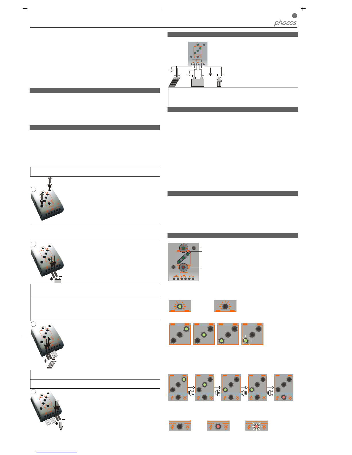
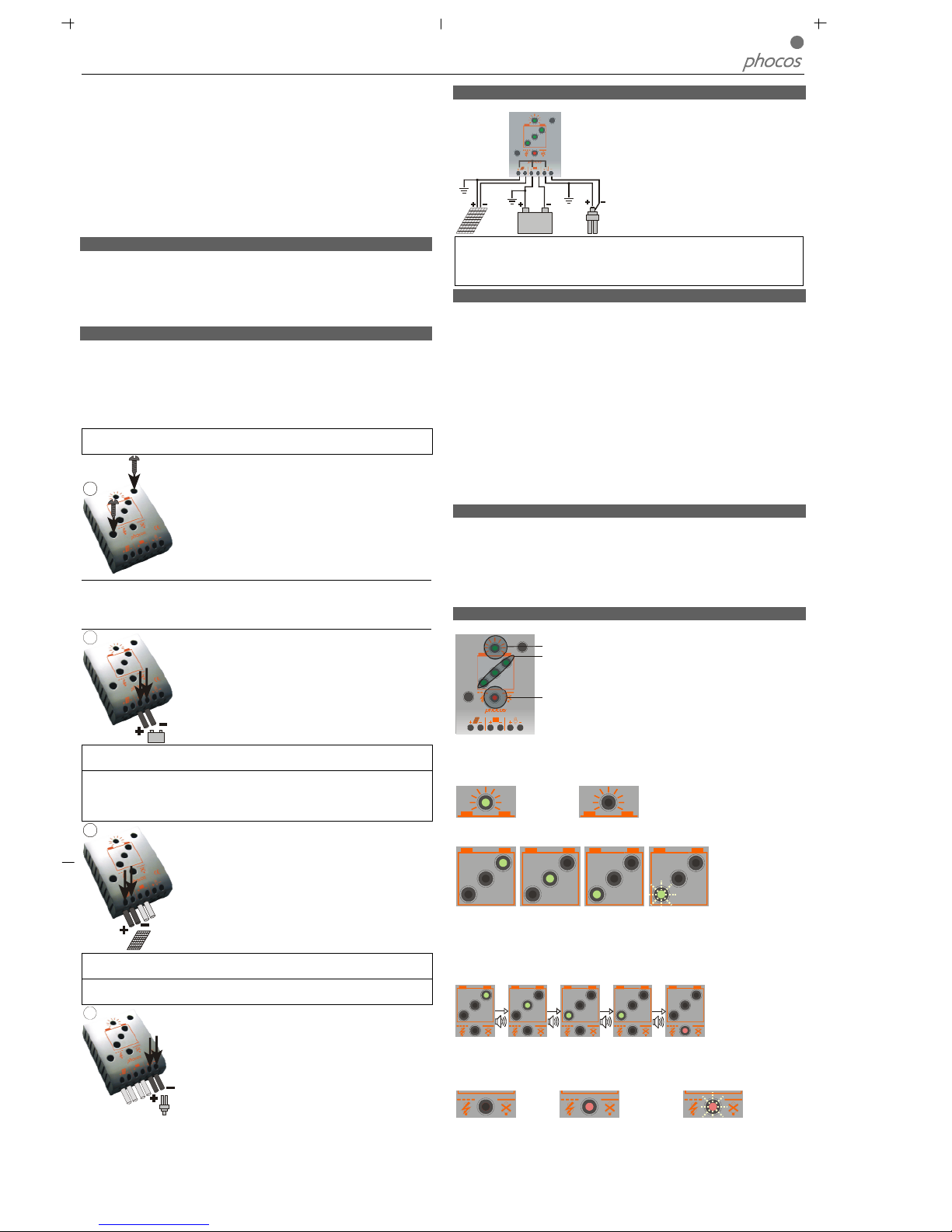
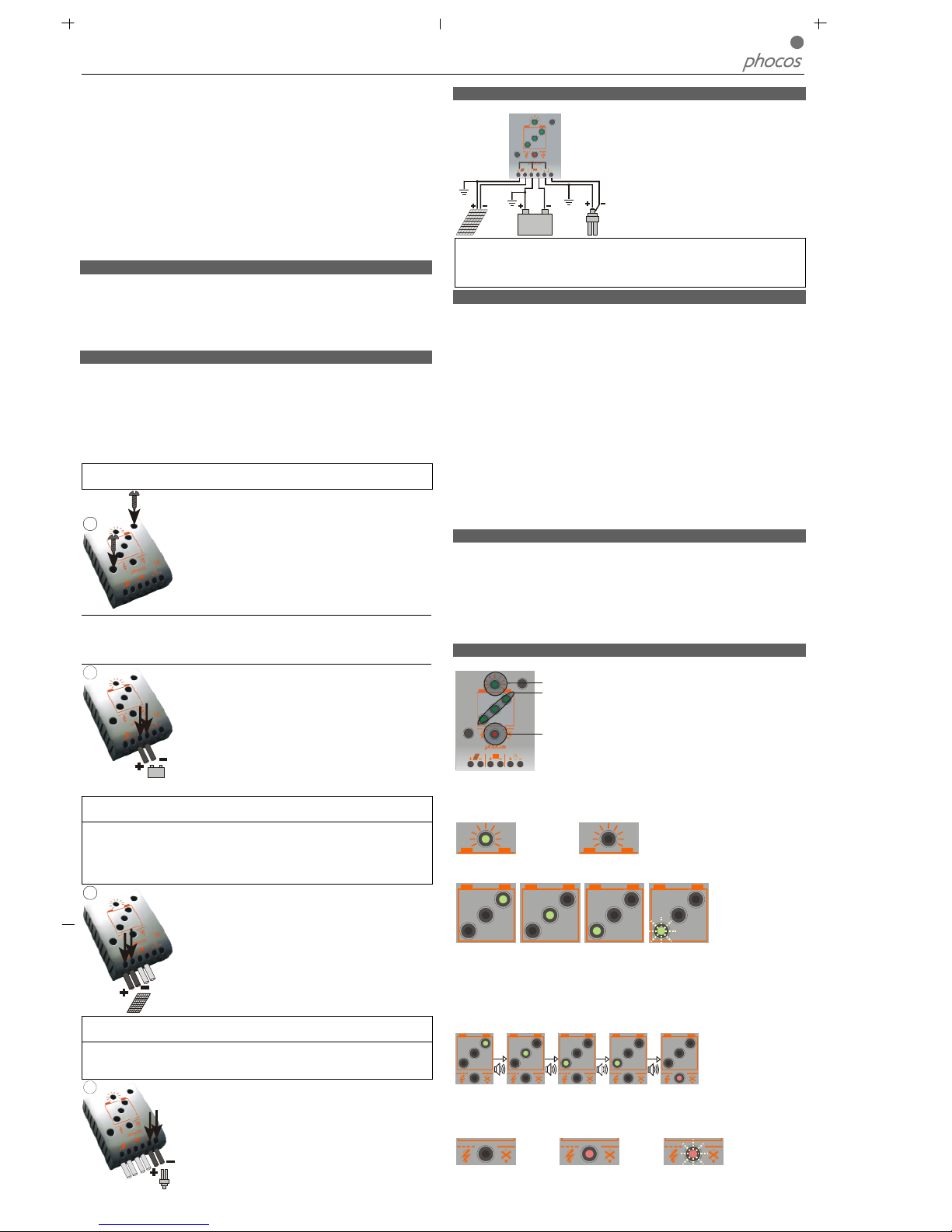
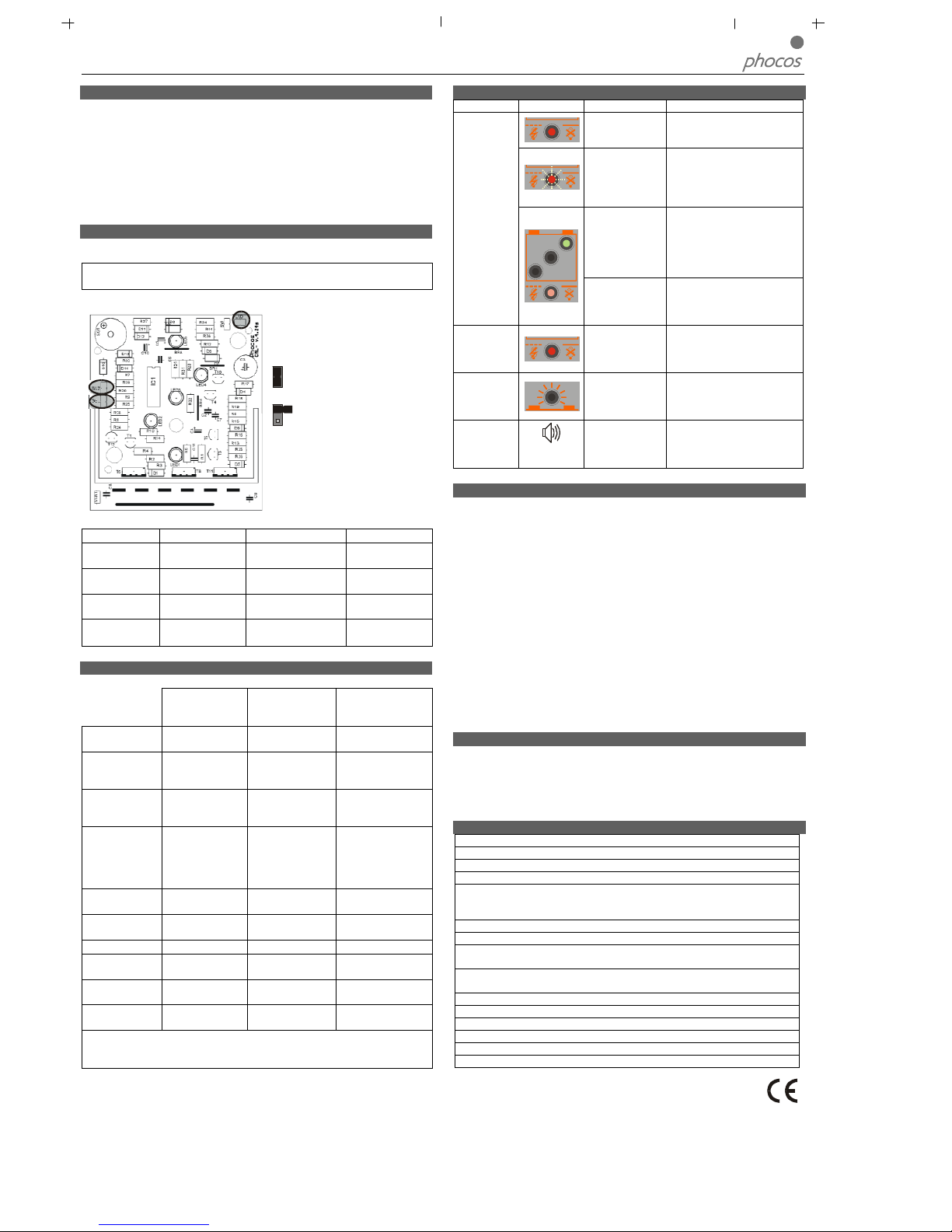
Anzeigefunktionen im Normalbetrieb
Der Regler verfügt über 5 Leuchtdioden und einen akustischen Alarm.
Ladungsanzeige
Ladezustandsanzeige
Lastzustandsanzeige
Im Normalbetrieb zeigt der Regler den Ladezustand der Batterie und die Ladung
durch das Solarmodul an. Jede Änderung des Ladezustandes nach unten wird akustisch
signalisiert.
Ladungsanzeige
Solarmodul liefert Strom Solarmodul liefert keinen Strom
Ladezustandsanzeige
>75% 25-75% <25% blinkt: <10%
Die Prozent-Angabe entspricht dabei der bis zum Tiefentlade-Abschaltpunkt entnehmbaren Energie in Relation zur vollgeladenen Batterie.
Akustische Signale
Bei einem Wechsel des Ladezustandes nach unten wird dies durch eine entsprechende Anzahl von Signaltönen signalisiert:
1x
3x
5x
25x
Die Lastabschaltung erfolgt ca. 1 Minute nach den 25 Signaltönen.
Lastzustandsanzeige
Der Regler schaltet bei Tiefentladung und bei Überlastung/Lastkurzschluss den Lastausgang ab. Dies wird signalisiert:
Normalbetrieb Tiefentladeschutz Überlastung oder
Lastkurzschluss

Solar-Laderegler CML05-2, CML08-2, CML10-2, CML15-2, CML20
Bedienungsanleitung Deutsch, Seite 2
Tiefentladeschutz (LVD)
Der Regler verfügt über 2 verschiedene Modi zum Schutz der Batterie gegen Tiefentladung.
1
. Ladezustandsgesteuert: Abschaltung 11,4 V (bei Last-Nennstrom) bis 11,9 V (bei
k
einem Laststrom). Modus mit guten Batterieschutz-Eigenschaften.
2. Spannungsgesteuert: Abschaltung 11,0 V fix, geeignet falls Verbraucher direkt an
die Batterie angeschlossen sind (z.B. Wechselrichter) und der Regler nicht den gesamten Laststrom erfassen kann.
W
erksseitig ist der Modus 1 voreingestellt. Die Einstellung des Modus ist unten
b
eschrieben.
Bei Unklarheiten über die Wahl des richtigen Modus wenden Sie sich an Ihren Händler, da dies nur in Zusammenhang mit der eingesetzten Batterie beurteilt werden kann.
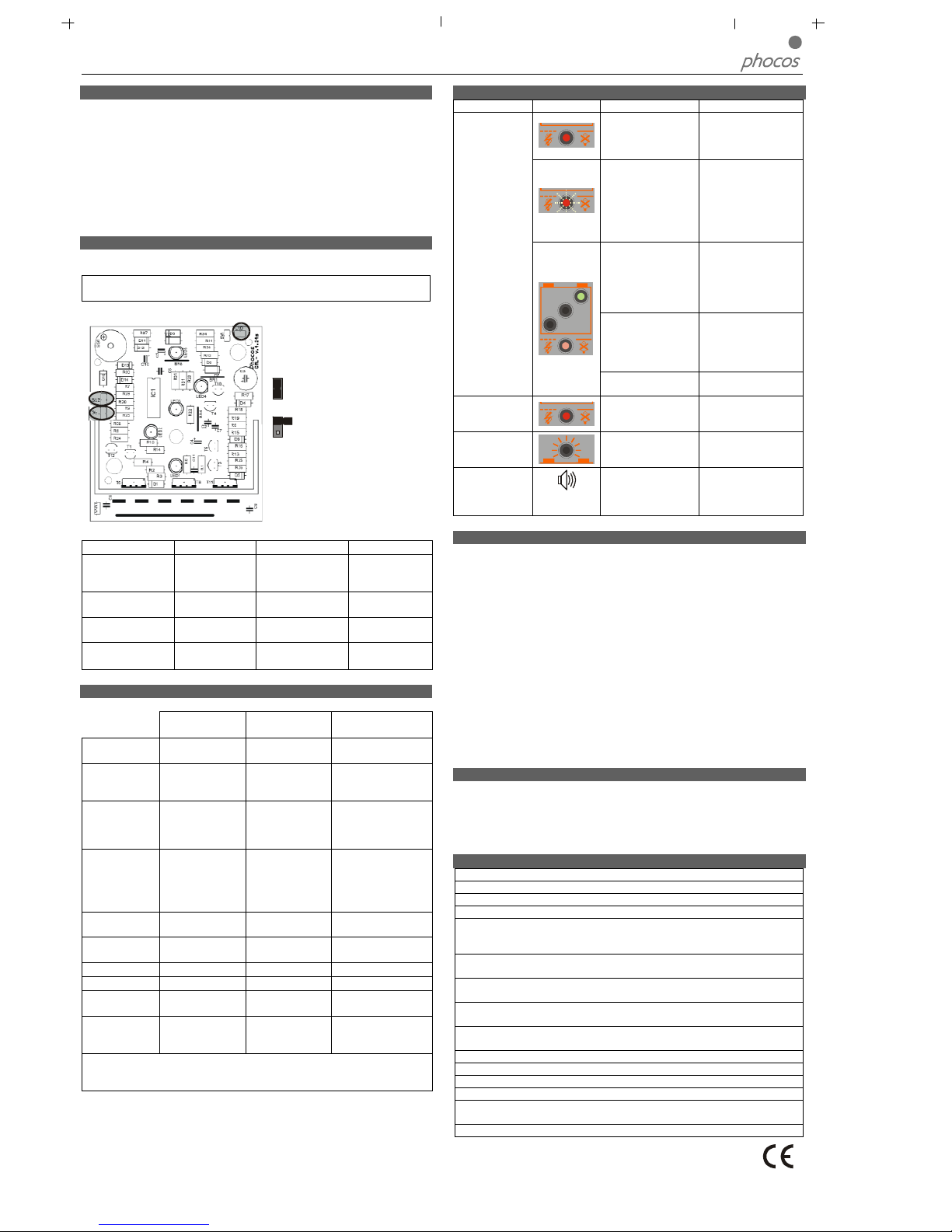
Einstellungen
Der Regler kann auf besondere Betriebsanforderungen eingestellt werden. Dazu ist
d
er Gehäusedeckel durch Lösen der rückseitigen Schraube abzunehmen.
WARNUNG: Der Regler darf keinesfalls in angeschlossenem Zustand geöffnet
werden!
B
ei geöffnetem Regler finden Sie 3 Steckbrücken (Jumper) auf der Elektronik-Platine:
Zum Umstellen stecken Sie die Steckbrücke entweder auf beide Kontaktstift
e oder nur auf einen Kontaktstift:
G
eschlossene Steckbrücke
1
3
2
O
ffene
Steckbrücke
Mit diesen Steckbrücken können folgende Einstellungen vorgenommen werden:
Steckbrücke GEL (1) LVD (2) BUZ (3)
Funktion Batterie-Bauart Funktion des
Tiefentladeschutzes
Akustischer Alarm
Einstellung Steckbrücke
offen
Flüssiger Elektrolyt
(geschlossene
Batterie)
Ladezustandsgesteuert
Alarm aus
Einstellung Steckbrücke
geschlossen
GEL (verschlossene Batterie)
Spannungsgesteuert
Alarm ein
Werkseinstellung Steckbrücke offen
(Flüssiger Elektrolyt)
Steckbrücke offen
Ladezustandsgesteuert
Steckbrücke
geschlossen
Alarm ein
Nach erfolgter Einstellung setzen Sie den Gehäusedeckel wieder auf und schrauben
ihn fest.
Schutzfunktionen
Der Regler ist an seinen Anschlüssen gegen fehlerhaften Betrieb geschützt:
Am SolargeneratorAnschluss
Am Batterie-Anschluss
Am Last-Anschluss
Batterie richtig
gepolt
Uneingeschränkt Normalbetrieb Uneingeschränkt
Batterie
verpolt
Uneingeschränkt
Ja, sofern nur Bat
terie
angeschlossen. Akustische Warnung
Uneingeschränkt
Verpolung
Ja, nicht bei 24V
Systemspannung
Ja, sofern nur Batterie
angeschlossen. Akustische Warnung
Gegen Überlastung
geschützt. Verbraucher
können u. U. geschädigt
werden.
Kurzschluss Uneingeschränkt
Uneingeschränkt.
WICHTIG: Absicherung direkt an der
Batterie.
Uneingeschränkt
Überstrom Kein Schutz -----------------------
Lastanschluss wird
abgeschaltet
Thermische
Überlastung
Kein Schutz -----------------------
Lastanschluss wird
abgeschaltet
Leerlauf Uneingeschränkt Uneingeschränkt Uneingeschränkt
Rückstrom Uneingeschränkt ----------------------- -----------------------
ÜberspannungVaristor 56 V, 2,3 J Bis 30 V
Lastanschluss wird
abgeschaltet
Unterspan-
nung
Normaler Betriebszustand
Lastanschluss wird
abgeschaltet
Lastanschluss wird
abgeschaltet
WARNUNG: Die Kombination verschiedener Fehler kann dem Regler Schaden
zufügen. Beheben Sie unbedingt zuerst den Fehler, bevor sie das Gerät weiter
anschließen.
Fehlerbeschreibung
Fehler Anzeige Ursache Abhilfe
Batterie ist
tiefentladen
Last schaltet automatisch zu,
w
enn die Batterie nachgeladen
w
urde
Überstrom /
Kurzschluss
Verbraucher
A
lle Verbraucher abschalten.
Ü
berstrom / Kurzschluss
beseitigen. Regler schaltet nach
ca. 1 Min. wieder ein
B
atteriespannung
i
st zu hoch (>
15,5 bzw. 31 V)
Überprüfen, ob fremde
Energiequellen die Batterie
laden. Falls nicht, ist der Regler
defekt.
Verbraucher haben
keine
Energie
B
atteriezuleitung
o
der BatterieSicherung defekt,
Batterie hochohmig
B
atterie-Zuleitungen und
Sicherung überprüfen, Batterie
überprüfen.
Batterie ist
nach kurzer
Zeit wieder
entladen
Batterie hat
Kapazität verloren
B
atterie austauschen
Batterie
w
ird
t
agsüber
nicht
geladen
Modulleitung
u
nterbrochen
o
der verpolt
Unterbrechung/Verpolung
beseitigen
Batterieverp
olung
D
auerton
Batterie verpolt
a
ngeschlossen
Batterie richtig anschließen
Allgemeine Sicherheits- und Verwendungshinweise
Bestimmungsgemäße Verwendung
Der Laderegler ist ausschließlich für den Einsatz in photovoltaischen Anlagen mit 12
oder 24 Volt Nennspannung und nur für den Betrieb mit geschlossenen oder verschlossenen Bleiakkumulatoren geeignet.
Sicherheitshinweise
Akkumulatoren enthalten große Mengen gespeicherter Energie. Vermeiden Sie
unter allen Umständen ein Kurzschließen des Akkumulators. Zur Sicherheit empfehlen wir, direkt an der Batterie eine Schmelzsicherung (träge) anzubringen.
Durch den Betrieb von Batterieanlagen können brennbare Gase entstehen. Ver-
meiden Sie unter allen Umständen die Bildung von Funken oder das Verwenden
von offenem Feuer oder Licht. Sorgen Sie für ausreichende Belüftung des Raumes,
in dem die Batterien betrieben werden.
Vermeiden Sie ein Berühren oder Kurzschließen der stromführenden Leiter und
Kontakte. Beachten Sie, dass die Spannungen an einzelnen Kontakten bis zum doppelten der Batterienennspannung betragen können. Arbeiten Sie nur mit isoliertem
Werkzeug, auf trockenem Untergrund und mit trockenen Händen.
Halten Sie Kinder von Batterie und Laderegler fern.
Bitte beachten Sie auch die sicherheitstechnischen Hinweise des Batterieherstellers.
Bei Zweifel oder Widersprüchen wenden Sie sich an Ihren Installateur oder Fachhändler.
Haftungsausschluss
Für Schäden durch nicht bestimmungsgemäßen Gebrauch, durch nicht Beachtung
dieser Anleitung oder der Angaben des Batterieherstellers kann keinerlei Haftung
übernommen werden, insbesondere nicht für Schäden an der Batterie. Dies gilt auch
für unsachgemäße Wartung, Betrieb, fehlerhafte Installation und falsche Systemdimensionierung.
Technische Daten
Systemnennspannung 12 / 24 V, automatische Erkennung
Spannung Hauptladung 14,5 / 29,0 V (25°C), 2 h
Spannung Ausgleichsladung 14,8 / 29,6 V (25°C), 2 h
Spannung Erhaltungsladung 13,7 / 27,4 V (25°C)
Tiefentladeschutz 11,4-11,9 / 22,8-23,8 V ladezustandsgesteuert
11,0 / 22,0 V spannungsgesteuert
Lastzuschaltspannung 12,8 / 25,6 V
Temperaturführung -4 mV/Zelle*K
Max. Modulstrom 5 / 8 / 10 / 15 / 20 A entspr. Typenbezeichnung bei
50°C Umgebungstemperatur
Max. Laststrom 5 / 8 / 10 / 15 / 20 A entspr. Typenbezeichnung bei
50°C Umgebungstemperatur
Abmessungen 80 x 100 x 32 mm (b x h x t)
Gewicht 180 gr
Max. Kabelquerschnitt 16 mm² (AWG #6)
Eigenverbrauch 4 mA
Temperaturbereich -25 bis + 50 °C
Schutzklasse IP 20
Änderungen vorbehalten. Version: CML041214
Made in one of the following countries: Germany – China – Bolivia - India
Phocos AG – Germany www.phocos.com
Solar Charge Controller CML05-2, CML08-2, CML10-2, CML15-2, CML20
User Manual English, Page 1
D
ear Client,
Thank you very much for buying a Phocos product. With your new CML controller
you own a state-of-the art device which was developed according to the latest
available technical standards. It comes with a number of outstanding features, like:
Clear, readable display of the state of charge
Acoustic signal when the state of charge changes
Low voltage disconnect regulated by state of charge or voltage
16 mm² connector clamps
Complete electronic protection
This manual gives important recommendations for installing, using and programming as
well as remedies in case of problems with the controller. Read it carefully in your own
i
nterest and mind the safety and usage recommendations at the end of this manual.
Description of Functions
The charge controller protects the battery from being overcharged by the solar
array and from being deep discharged by the loads. The charging characteristics
include several stages which include automatic adaptation to the ambient tempera-
ture.
The charge controller adjusts itself automatically to 12V or 24V system voltage.
The charge controller has a number of safety and display functions.
Mounting and Connecting
The controller is intended for indoor use only. Protect it from direct sunlight and place
it in a dry environment. Never install it in humid rooms (like bathrooms).
The controller measures the ambient temperature to determine the charging voltage.
C
ontroller and battery must be installed in the same room.
The controller warms up during operation, and should therefore be installed on a non
flammable surface only.
REMARK: Connect the controller by following the steps described below to avoid
installation faults.
1
Mount the controller to the wall with screws that fit to the wall
m
aterial. Use screws with 4 mm shaft and max. 8 mm head
d
iameter, no counter sunk. Mind that the screws have to carry
also the force applied by the wiring.
Make sure that the ventilator slits on the sides are unobstructed.
A DIN Rail mounting plate is available as an accessory (CX-DR2). This allows mounting the controller on a standard 35mm DIN rail. Remove the screws at the
backside of
the controller and screw the mounting plate with the (long) fastening screw onto the
backside of the controller.
2
Connect the wires leading to the battery with correct polarity.
To avoid any voltage on the wires, first connect the controller,
then the battery. Mind the recommended wire length (min 30
cm to max approx. 100 cm) and the wire size:
CML05: min 2.5 mm²
CLM08: min 4 mm²
CML10: min 6 mm²
CML15, CML20: min 10 mm²
Wrong polarity will cause a permanent warning sound.
WARNING: If the battery is connected with reverse polarity, the load terminals
will also have the wrong polarity. Never connect loads during this condition!
REMARK: Mind the recommendations of your battery manufacturer. We strongly
recommend connecting a fuse directly to the battery to protect any short circuit at the
battery wiring. The fuse must take the charge controller nominal current:
CML05: 20A, CML08: 20A, CML10: 30A, CML15: 30A, CML20: 40A
3
Connect the wires leading to the solar array with correct
polarity. To avoid any voltage on the wires, first connect the
controller, then the solar array. Mind the recommended wire
size:
CML05: min 2.5 mm²
CLM08: min 4 mm²
CML10: min 6 mm²
CML15, CML20: min 10 mm²
REMARK: Place positive and negative wire close to each other to minimize electromagnetic effects.
REMARK: Solar panels provide voltage as soon as exposed to sun light. Mind the solar
panel manufacturer’s recommendations in any case.
4
Connect the wires leading to the loads with correct polarity.
To avoid any voltage on the wires, first con
nect the wire to the
load, then to the controller. Mind the recommended wire size:
CML05: min 2.5 mm²
CLM08: min 4 mm²
CML10: min 6 mm²
CML15, CML20: min 10 mm²
Grounding the Solar System
B
e aware that the positive terminals of the
CML controller are connected internally and
therefore have the same electrical potential. If
any grounding is required, always do this on
the positive wires.
R
EMARK: If the device is used in a vehicle which has the battery negative on the
chassis, loads con
nected to the controller must not have an electric connection to the
car body, otherwise the Low Voltage Disconnect and electronic fuse functions of the
controller are short circuited.
Starting up the Controller
Self Test
A
s soon as the controller is supplied with power either from the battery or the solar
a
rray, it starts a self test routine. Then the display changes to normal operation.
System Voltage
The controller adjusts itself automatically to 12 V or 24 V system voltage.
A
s soon as the voltage at the time of start-up exceeds 20.0 V, the controller implies a
24 V system.
If the battery voltage is not within the normal operation range (ca. 12 to 15.5 V or ca.
24 to 31 V) at start-up, a status display according to the section ERROR DESCRIPT
ION occurs.
Battery Type
The controller is preset to operate with lead acid batteries with liquid electrolyte. If
you intend to use a lead-acid battery with solid electrolyte ('gel' type or 'fleece' type)
y
ou can adjust the charging characteristics (see "Settings"). The equalization charge is
deactivated then.
In case of any doubts consult your dealer.
Recommendations for Use
The controller warms up during normal operation.
T
he controller does not need any maintenance or service. Remove dust with a dry
tissue.
It is important that the battery gets fully charged frequently (at least monthly). Otherwise the battery will be permanently damaged.
A battery can only be fully charged if not too much energy is drawn during charging.
Keep that in mind, especially if you install additional loads.
Display Functions
The controller is equipped with 5 LEDs and an acoustic warning signal.
Charge display
State of charge display
Load status display
In normal operation, the controller shows the state of charge of the battery and the
charge from the solar panels. Any change of the state of charge (SOC) to a lower
status is additionally signaled acoustically.
Charge display
Solar array supplies electricity Solar array does not supply electricity
State of charge display
>75% 25-75% <25% flashes: <10%
The percentage corresponds to the available energy until Low Voltage Disconnect in
relation to a fully charged battery.
Acoustic signals
A change in the state of charge (SOC) to a lower status is indicated by an acoustic
signal.
1x
3x
5x
25x
The loads are disconnected approx. 1 minute after a series of 25 signals.
Load status display
In case of deep discharge or overload/short-circuit of load, the load output is switched
off. This is indicated by:
Normal operation Low voltage disconnect Overload or Short-circuit of load

Solar Charge Controller CML05-2, CML08-2, CML10-2, CML15-2, CML20
User Manual English, Page 2
Low Voltage Disconnect Function (LVD)
T
he controller has 2 different modes to protect the battery from being deeply
d
ischarged:
1. State of charge controlled: Disconnect at 11.4 V (at nominal load current) up to
11.9 V (at no load current). Normal operation mode for good battery protection.
2
. Voltage controlled: Disconnect at 11.0 V fixed setting. Appropriate if bypass loads
d
raw current directly from the battery.
The controller is preset to Mode 1 from the factory. Changing the mode setting is
described below.
In case of doubts which mode to choose, consult your dealer because this has to be
e
valuated depending on the battery used.
Settings
T
he controller can be configured for special operation. For this purpose, open the
cover of the controller by removing the screws on the back side.
WARNING: The controller should not be opened while connected and in operat
ion!
When the controller is opened, there are 3 jumpers on the electronic board:
F
or changing, put the jumper either on
b
oth contact pins or only on one
contact pin:
Closed jumper
1
3
2
Open
jumper
With these jumpers, the following settings can be configured:
Jumper GEL (1) LVD (2) BUZ (3)
Function Battery type Function of low voltage
disconnect
Acoustic alarm signal
Setting jumper
open
Liquid
electrolyte
State of charge controlled
Alarm off
Setting jumper
closed
GEL (VRLA
battery)
Voltage controlled Alarm on
Factory setting Jumper open
(liquid electrolyte)
Jumper open state-ofcharge controlled
Jumper closed
Alarm on
After completing the setting, replace the cover and tighten it with the screws.
Safety Features
The controller is protected against wrong installation or use:
At the solar terminal
At the battery
terminal
At the load terminal
Battery connected
with correct polarity
Unrestricted Normal operation Unrestricted
Battery connected
with wrong polarity
Unrestricted
Unrestricted. Acous-
tic Warning
Unrestricted
Reverse polarity
Yes, not at 24V
system voltage.
Yes, if only the
battery is connected.
Acoustic Warning
Load output is
protected. Loads
might be damaged.
Short circuit Unrestricted
Unrestricted.
CAUTION: Battery
must be protected
by fuse.
Unrestricted
Overcurrent No protection -----------------------
Controller switches
off load terminal.
Thermal overload No protection -----------------------
Controller switches
off load terminal.
No connection Unrestricted Unrestricted Unrestricted
Reverse Current Unrestricted ----------------------- -----------------------
Overvoltage Varistor 56 V, 2,3 J Max. 40 V
Controller switches
off load terminal.
Undervoltage Normal operation
Controller switches
off load terminal.
Controller switches
off load terminal.
WARNING: The combination of different error conditions may cause damage to
the controller. Always remove the error before you continue connecting the
controller!
Error Description
E
rror Display Reason Remedy
Battery is low
Load will reconnect as
soon as battery is
recharged.
O
vercurrent/ Short
circuit of loads
Switch off all loads.
Remove short circuit.
Controller will switch
o
n load automatically
a
fter max 1 minute.
B
attery voltage too
high (>15.5 / 31.0 V)
C
heck if other sources
o
vercharge the battery.
If not, controller is
damaged.
Loads are not
s
upplied
Battery wires or
battery fuse damaged,
b
attery has high
r
esistance
Check battery wires,
f
uses and battery.
B
attery is empty
a
fter a short
time
Battery has low
capacity
C
hange battery
B
attery is not
being charged
during the day
Solar array faulty or
wrong polarity
R
emove faulty connec-
tion/reverse polarity
Battery wrong
polarity
P
ermanent
s
ound
Battery is connected
with reverse polarity
Remove reverse
polarity
General Safety and Usage Recommendations
Intended Use
The charge controller is intended exclusively for use in photovoltaic systems with 12 V
or 24 V nominal voltage and in conjunction with vented or sealed (VRLA) lead acid
batteries only.
Safety Recommendations
Batteries store a large amount of energy. Never short circuit a battery under all
circumstances. We recommend connecting a fuse (slow acting type, according to
t
he nominal controller current) directly to the battery terminal.
Batteries can produce flammable gases. Avoid making sparks, using fire or any naked
flame. Make sure that the battery room is ventilated.
Avoid touching or short circuiting wires or terminals. Be aware that the voltages on
specific terminals or wires can be up to double the battery voltage. Use isolated
tools, stand on dry ground and keep your hands dry.
Keep children away from batteries and the charge controller.
Please observe the safety recommendations of the battery manufacturer. If in
doubt, consult your dealer or installer.
Liability Exclusion
The manufacturer shall not be liable for damages, especially on the battery, caused by
use other than as intended or as mentioned in this manual or if the recommendations
of the battery manufacturer are neglected. The manufacturer shall not be liable if
there has been service or repair carried out by any unauthorized person, unusual use,
wrong installation, or bad system design.
Technical Data
Nominal voltage 12 / 24 V, automatic recognition
Boost voltage 14.5 / 29.0 V (25°C), 2 h
Equalization voltage 14.8 / 29.6 V (25°C), 2 h
Float voltage 13.7 / 27.4 V (25°C)
Low Voltage Disconnect
Function
11.4-11.9 / 22.8-23.8 V controlled by state of charge
11.0 / 22.0 V controlled by voltage
Load reconnect voltage 12.8 / 25.6 V
Temperature compensation
-4 mV/cell*K
Max. solar panel current 5 / 8 / 10 / 15 / 20 A according to model number @
50°C
Max. load current 5 / 8 / 10 / 15 / 20 A according to model number @
50°C
Dimensions 80 x 100 x 32 mm (w x h x d)
Weight 180 gr
Max. wire size 16 mm² (AWG #6)
Self consumption 4 mA
Ambient temperature
range
-25 to + 50 °C
Case protection IP 20
Subject to change without notice. Version: CML041214
Made in one of the following countries: Germany – China – Bolivia - India
Phocos AG – Germany www.phocos.com

Controlador de Carga Solar CML05-2, CML08-2, CML10-2, CML15-2, CML20
Manual de Instrucciones en Español, Página 1
E
stimado Usuario,
Muchas gracias por adquirir un producto de Phocos. Con su nuevo controlador CML,
Ud. posee un aparato moderno que ha sido diseñado siguiendo los últimos criterios
técnicos disponibles. Incorpora toda una serie de características sobresalientes, como:
Visualización clara y legible del estado de la carga
Señal acústica cuando el estado de carga cambia
Desconexión por bajo voltaje regulada por el estado de carga o por el voltaje
abrazaderas de conector de 16 mm²
Protección electrónica completa
Este manual da recomendaciones claves para la instalación, utilización y programación,
así como soluciones en caso de que tenga problemas con el controlador. Por su
p
ropio bien, léalo detenidamente; en particular, las recomendaciones sobre uso y
s
eguridad descritas en las últimas páginas.
Descripción de las Funciones
El controlador de carga protege a la batería contra posible sobrecarga del modulo
solar y evita que sea fuertemente descargada durante los consumos. Las
características de carga comprenden diversos estadios que incluyen la adaptación
automática a la temperatura ambiente.
El controlador de carga se ajusta automáticamente al sistema de voltaje de 12V o 24V.
El controlador de carga tiene varias funciones de seguridad y de visualización.
Montaje y Conexión
El controlador debe funcionar únicamente en interiores. Protéjalo de la luz directa del
sol y colóquelo en un lugar seco. No debe instalarlo nunca en habitaciones húmedas
(como baños).
El controlador mide la temperatura ambiente para determinar el voltaje de carga. El
controlador y la batería deben instalarse en la misma habitación.
El controlador se calienta durante su funcionamiento y por lo tanto ha de instalarse
únicamente en una superficie no inflamable.
OBSERVACIÓN: Para evitar errores de instalación, conecte el controlador siguiendo
los pasos descritos a continuación.
1
Fije el controlador a la pared con tornillos adecuados a la
s
uperficie de la misma. Use tornillos de 4 a 5 Mm. de eje y 8
M
m. de diámetro. Tenga en cuenta que los tornillos deben
soportar la fuerza aplicada en el cableado.
Asegúrese que las hendeduras laterales del ventilador no estén
obstruidas.
Dispone como accesorio de una placa de instalación con carril DIN (CX-DR2).
Permite montar el controlador en un carril DIN estándar de 35mm. Quite los tornillos
de la parte trasera del controlador y atornille en la misma la placa de instalación con el
tornillo de sujeción (largo).
2
Conecte el cableado a la batería con la polaridad correcta. Para
evitar voltaje en los cables, conecte primero el controlador y
luego la batería. Tenga en cuenta la longitud de cable
recomendada (mín. de 30 cm. a máx. aprox.de 100 cm.) y el
tamaño del cable:
CML05: mín. 2,5 mm²
CLM08: mín. 4 mm²
CML10: mín 6 mm²
CML15, CML20: mín 10 mm²
La polaridad incorrecta causará un permanente sonido de
advertencia.
ADVERTENCIA: Si se conecta la batería con polaridad inversa, la polaridad de los
bornes de carga también será incorrecta. ¡No conecte nunca cargas bajo estas
condiciones!
OBSERVACIÓN: Siga las recomendaciones del fabricante de su batería.
Recomendamos encarecidamente conectar un fusible directamente a la batería para
evitar cortocircuitos en el cableado de la misma. El fusible debe tener la corriente
nominal del controlador de carga:
CML05: 20A, CML08: 20A, CML10: 30A, CML15: 30A, CML20: 40A
3
Conecte con la polaridad correcta los cables dirigidos al
módulo solar. Para evitar voltaje en los cables, con
ecte primero
el controlador y luego el módulo solar. Tenga en cuenta el
tamaño de cable recomendado:
CML05: mín. 2,5 mm²
CLM08: mín. 4 mm²
CML10: mín 6 mm²
CML15, CML20: mín 10 mm²
OBSERVACIÓN: para minimizar los efectos electromagnéticos coloque el cable
positivo al lado del cable negativo.
OBSERVACIÓN: Los paneles solares suministran voltaje en cuanto quedan expuestos
a la luz del sol. Siga en todos los casos las recomendaciones del fabricante del panel
solar.
4
Conecte con la polaridad correcta los cables dirigidos a los
consumos. Para evitar voltaje en los cables, conecte primero el
cable a la carga y luego al controlador. Tenga en cuenta el
tamaño de cable recomendado:
CML05: mín. 2,5 mm²
CLM08: mín. 4 mm²
CML10: mín 6 mm²
CML15, CML20: mín 10 mm²
Toma de tierra del Sistema Solar
T
enga en cuenta que los bornes positivos del
controlador CML están conectados
internamente y, por lo tanto, tienen el mismo
potencial eléctrico. Si se requiere toma de
corriente, efectúela siempre en los cables
p
ositivos.
O
BSERVACIÓN: Si se utiliza el aparato en un vehículo que tenga el negativo de la
batería en el chasis, los consumos conectados al controlador no deben tener una
conexión eléctrica a la carrocería; de otro modo se provocaría un cortocircuito en las
funciones de Desconexión por Bajo Voltaje y de fusible electrónico.
Activar el controlador
Test Automático
A
cto seguido a que el controlador reciba corriente, ya sea de una batería o de un
m
ódulo solar, éste ejecuta un autotest rutinario. Luego la visualización cambia a
funcionamiento normal.
V
oltaje del Sistema
E
l controlador de carga se ajusta automáticamente al sistema de voltaje de 12V o 24V.
Si durante el encendido el voltaje excede de 20,0 V, el controlador cambia a un
sistema de 24 V.
Durante el encendido, si el voltaje de la batería no está dentro de la escala normal de
f
uncionamiento (ca. 12 a 15,5 V o ca. 24 a 31 V), se muestra un MENSAJE DE
E
RROR.
Tipo de Batería
El controlador está programado para funcionar con baterías de plomo de electrolito
l
íquido. Si piensa usar la batería de plomo con electrolito sólido (tipo 'gel' o tipo
'vellón') puede ajustar las características de carga (ver "Configuración"). En ese caso se
desactivará la carga de ecualización.
Si tiene alguna duda consulte con el vendedor.
Recomendaciones de Uso
El controlador se calienta mientras está en funcionamiento.
El controlador no requiere ningún mantenimiento o revisión. Quite el polvo con un
trapo seco.
Es importante que la batería se cargue completamente con frecuencia (al menos una
vez por mes). De otro modo, la batería estará permanentemente dañada.
Una batería solo puede estar completamente cargada si durante los consumos no se
pierde mucha energía. Tenga esto en cuenta, especialmente si instala consumos
adicionales.
Funciones de Visualización
El controlador dispone de 5 LEDs y de una señal acústica de aviso.
Visualización de la carga
Visualización del estado de la
carga
Visualización del estado del
consumo
En funcionamiento normal, el controlador muestra el estado de la carga de la batería y
el estado de la carga de los paneles solares. Adicionalmente, cualquier descenso del
estado de la carga (SOC) se señala acústicamente.
Visualización de la carga
El módulo solar suministra electricidad El módulo solar no suministra
electricidad
Visualización del estado de la carga
>75% 25-75% <25% destellos: <10%
El porcentaje indica la relación entre la energía disponible de una batería
completamente cargada, y el mínimo indicado con Desconexión por Bajo Voltaje.
Señales acústicas
El descenso del estado de la carga (SOC) se indica mediante una señal acústica.
1x
3x
5x
25x
Se desconectan los consumos aprox.. 1 minuto después de una serie de 25 pitidos.
Visualización del estado del consumo
En caso de descarga profunda o sobrecarga/cortocircuito de la carga, se desconecta la
salida del consumo. Esto se indica por:
Funcionamiento Normal Desconexión Sobrecarga o
por bajo voltaje Cortocircuito del
consumo
Controlador de Carga Solar CML05-2, CML08-2, CML10-2, CML15-2, CML20
Manual de Instrucciones en Español, Página 2
Función de Desconexión por Bajo Voltaje (LVD)
E
l controlador tiene 2 modos diferentes para proteger a la batería de una descarga
p
rofunda:
1. estado de la carga controlado: Desconecta de 11,4 V (a corriente de carga
nominal) hasta 11,9 V (a falta de corriente). Modo de funcionamiento normal para
una buena protección de la batería.
2
. Voltaje controlado: Desconecta en el parámetro de 11,0 V. Apropiado si otros
consumos retiran corriente directamente de la batería.
Salido de fábrica, el controlador está programado en el Modo 1. Se describe debajo
como cambiar la configuración del modo.
E
n caso de que dude sobre el modo a escoger, consulte con el vendedor ya que
dependerá de la batería que utilice.
Configuración
Puede configurarse el controlador para funcionamientos especiales. Para este
propósito, abra la cubierta del controlador quitando los tornillos de su parte trasera.
ADVERTENCIA: ¡No debe abrirse el controlador si está conectado y si está
f
uncionando!
Cuando abra el controlador, verá 3 puentes en la placa electrónica:
P
ara cambiar, ponga el puente ya sea
en ambas clavijas de contacto o solo
en una:
Puente cerrado
1
3
2
Puente
abierto
Pueden configurarse los siguientes parámetros con estos puentes:
P
uente GEL (1) LVD (2) BUZ (3)
Función Tipo de batería
Alarma acústica
Parámetro de puente
abierto
Electrolito líquido
(batería cerrada)
Estado de la carga
controlado
Alarma desactivada
Parámetro de puente
cerrado
GEL (batería
cerrada)
Voltaje controlado Alarma activada
Parámetro de
funcionamiento
Puente abierto
(electrolito líquido)
Puente abierto, estado
de la carga controlado
Puente cerrado
Alarma activada
Tras completar la configuración, vuelva a poner la cubierta y fíjela con los tornillos.
Características de Seguridad
El controlador está protegido contra una instalación o uso erróneos:
En el borne de la
instalación solar
En el borne de la
batería
En el borne de carga
ía conectada con
polaridad correcta
Totalmente
Funcionamiento
Normal
Totalmente
Batería conectada
con polaridad
equivocada
Totalmente
Totalmente. Aviso
Acústico
Totalmente
Polaridad inversa
Sí, no con un sis
tema
de voltaje de 24V.
Sí, solamente si la
batería está
conectada. Aviso
Acústico
La salida del consumo
está protegida. Los
consumos pueden estar
dañados.
Cortocircuito. Totalmente
Totalmente.
PRECAUCIÓN:
Debe protegerse la
batería con un
fusible.
Totalmente
Sobrecorriente Sin protección -----------------------
El controlador desactiva
el borne de carga.
Sobrecarga
térmica
Sin protección -----------------------
El controlador desactiva
el borne de carga.
Sin conexión Totalmente Totalmente Totalmente
Corriente Inversa Totalmente ----------------------- -----------------------
Sobrevoltaje Varistor 56 V, 2,3 J Máx. 40 V
El controlador desactiva
el borne de carga.
Bajo voltaje
Funcionamiento
Normal
El controlador
desactiva el borne
de carga.
El controlador desactiva
el borne de carga.
ADVERTENCIA: La co
mbinación de diferentes circunstancias de error puede dañar
al controlador. ¡Corrija siempre un error antes de proseguir con la conexión del
controlador!
Descripción de Errores
E
rror Circunstancia
C
ausa Solución
L
a batería está baja
El consumo se volverá
a conectar tan pronto
como la batería esté
recargada.
S
obre corriente/
C
ortocircuito de
consumos
Desconectar todos los
consumos. Suprimir
c
ortocircuito. El
c
ontrolador activará
automáticamente el
consumo después de 1
minuto, como máximo.
E
l voltaje de la
batería es demasiado
alto (>15,5 / 31,0 V)
Compruebe que otras
fuentes no estén
sobrecargando la
batería. De otro modo,
s
e dañará el
controlador.
L
os cables o el fusible
d
e la batería están
dañados, la batería
tiene una alta
resistencia
Comprobar los cables
y fusibles de la batería
y el estado de la
m
isma.
No se
suministran los
consumos.
La batería tiene baja
capacidad
C
ambiar la batería
La batería se
vacía después de
poco tiempo
ódulo Solar
defectuoso o
polaridad equivocada
la conexión defectuosa
o la polaridad inversa
La batería no se
carga durante el
día
La batería está
conectada con
polaridad inversa
Corrija la polaridad
i
nversa de la batería
Batería con
polaridad
equivocada
Sonido
permanente
Recomendaciones Generales sobre Seguridad y Manejo
Uso Establecido
El controlador de carga está diseñado exclusivamente para sistemas fotovoltaicos con
12 V o 24 V de voltaje nominal y en conjunción solamente con baterías de plomo con
aberturas o selladas (VRLA).
Recomendaciones Generales de Seguridad
Las baterías almacenan una gran cantidad de energía. Bajo ninguna circunstancia,
ponga una batería en cortocircuito. Recomendamos conectar un fusible (de acción
lenta, de acuerdo con la corriente del controlador nominal) directamente al borne
de la batería.
Las baterías pueden producir gases inflamables Evite que se produzcan chispas a
causa del empleo de fuego o de algún tipo de llama. Asegúrese que el espacio de la
batería esté bien ventilado.
Evite tocar o provocar cortocircuito en los cables o bornes. Tenga en cuenta que el
voltaje en bornes o cables específicos puede doblar el voltaje de la batería. Emplee
herramientas aislantes, opere en un lugar seco y mantenga sus manos secas.
Manténgase a los niños alejados de las baterías y del controlador de carga.
Por favor, cumpla con las recomendaciones de seguridad del fabricante de la
batería. Si tiene alguna duda, consulte con el vendedor o con el instalador.
Exclusión de Responsabilidad
El fabricante no se responsabiliza de los daños, especialmente en la batería, causados
por un uso del controlador diferente para el que está pensado e indicado en este
manual o si se no se siguen las recomendaciones del fabricante de la batería. El
fabricante no se responsabiliza si ha habido un servicio o reparación llevado a cabo
por una persona no autorizada, uso irregular, instalación incorrecta o mal diseño de
sistema.
Datos Técnicos
Voltaje nominal 12 / 24 V, reconocimiento automático
Voltaje de carga profunda 14,5 / 29,0 V (25°C), 2 h
Voltaje de ecualización 14,8 / 29,6 V (25°C), 2 h
Voltaje de flotación 13,7 / 27,4 V (25°C)
Función de Desconexión
por Bajo Voltaje
11,4-11,9 / 22,8-23,8 V controlado por el estado de
carga
11,0 / 22,0 V controlado por el voltaje
Voltaje de reconexión de
carga
12.8 / 25.6 V
Compensación de
temperatura
-4 mV/Cell*K
Máx. corriente de panel
solar
5 / 8 / 10 / 15 / 20 A de acuerdo con el número de
modelo @ 50°C
Máx. corriente de carga 5 / 8 / 10 / 15 / 20 A de acuerdo con el número de
modelo @ 50°C
Dimensiones 80 x 100 x 32 mm (w x h x d)
Peso 180 gr
Máx. tamaño de cable 16 mm² (AWG #6)
Autoconsumo 4 mA
Escala de temperatura
ambiental
-25 a + 50 °C
Caja de protección IP 20
Sujeto a cambios sin aviso. Versión: CML041214
Hecho en uno de los siguientes países: Alemania– China – Bolivia - India
Phocos AG – Alemania www.phocos.com

Contrôleur de Charge Solaire CML05-2, CML08-2, CML10-2, CML15-2, CML20
Guide de l'Utilisateur en Français, Page 1
C
her Client,
Merci beaucoup d'acheter un produit Phocos. Avec votre nouveau contrôleur CML,
vous avez un système d'avant-garde, qui a été développé selon les dernières techniques, aux normes, disponibles. Il est fourni avec un certain nombre de caractéristiques
é
tonnantes, telles que :
Affichage clair et lisible de l'état de charge
Signal Sonore lorsque l'état de charge change
Débranchement à basse tension contrôlé par l'état de charge ou le voltage
Caleurs de connexion de 16 mm²
Protection électronique totale
Ce manuel donne des recommandations d'installation importantes, d'utilisation et de
p
rogrammation, ainsi que des solutions pour résoudre les problèmes rencontrés avec
v
otre contrôleur. Dans votre propre intérêt, lisez le attentivement, et respectez les
recommandations de sécurité et d'utilisation à la fin du manuel.
Description des fonctions
Le contrôleur de charge protège la batterie du risque de surcharge par le généra-
teur solaire, et de décharge profonde par les charges. Les caractéristiques de char-
gement comportent plusieurs étapes qui incluent l'adaptation automatique à la
t
empérature ambiante.
Le contrôleur de charge s'ajuste automatiquement à la tension du système en 12V
ou 24V.
Le contrôleur de charge est équipé de fonctions de sécurité et d'affichage.
Montage et Connexion
L'utilisation du contrôleur n'est prévu qu'en intérieur. Le placer dans un environnem
ent sec et à l'abri des rayonnements directs du soleil. Ne jamais l'installer dans des
pièces humides (comme une salle de bain).
Le contrôleur mesure la température ambiante pour déterminer le voltage du chargement. Le contrôleur et la batterie doivent être installés dans la même pièce.
L
e contrôleur chauffe lors du fonctionnement, et doit donc être installé, uniquement,
sur une surface non-inflammable.
R
EMARQUE : Connectez le contrôleur en suivant les étapes décrites ci-dessous, afin
d
'éviter les erreurs d'installation.
1
M
ontez le contrôleur sur le mur avec des vis adaptées au
matériel du mur. Utilisez des vis de longueur de 4 à 5 mm et
ayant une tête de diamètre de 8 mm maximum, non fraisées.
N'oubliez pas que les vis doivent porter aussi la force appliquée
par le câblage.
Assurez vous que les fentes du ventilateur, sur les côtés, ne
sont pas obstruées.
Une plaque de montage sur rail aux normes DIN est disponible en tant qu'accessoire
(CX-DR2). Cette plaque permet de monter le contrôleur sur un rail DIN standard de
35mm. Retirez les vis au dos du contrôleur et vissez la plaque de montage avec la
(longue) vis de fixation au dos du contrôleur.
2
Connectez les câbles à la batterie avec la polarité adéquate.
Afin d'éviter toute tension sur les câbles, connectez tout
d'abord le contrôleur et après la batterie. Rappelez-vous que
la longueur de câble recommandée est, (approximativement,
de 30 cm minimum et de 100 cm maximum) et la taille du
câble de :
CML05: min 2,5 mm², CLM08: min 4 mm²
CML10: min 6 mm², CML15, CML20: min 10 mm²
Une polarité incorrecte causera une tonalité d'avertissement
permanente.
ATTENTION : Si la batterie est connectée en polarité inversée, les bornes de
charge auront aussi une polarité incorrecte. Ne jamais connecter les charges dans
ces conditions!
REMARQUE : Respectez les recommandations de votre fabricant de batterie. Nous
vous recommandons, fortement, de connecter un
fusible directement à la batterie, afin
d'éviter tout court-circuit au câblage de la batterie. Le fusible doit prendre le courant
nominal du contrôleur de charge :
CML05: 20A, CML08: 20A, CML10: 30A, CML15: 30A, CML20: 40A
3
Connectez les câbles au générateur solaire avec la polarité
adéquate. Afin d'éviter toute tension sur les câbles, connectez
tout d'abord le contrôleur et après le générateur solaire.
Respectez les recommandations pour la taille des câbles:
CML05: min 2,5 mm²
CLM08: min 4 mm²
CML10: min 6 mm²
CML15, CML20: min 10 mm²
REMARQUE : placez le câble positif et le câble négatif près l'un de l'autre, afin de
minimiser les effets électromagnétiques.
REMARQUE : Les panneaux solaires fournissent du voltage dès qu'ils sont exposés à la
lumière du soleil. Dans tous les cas, respectez les recommandations des fabricants de
panneaux solaires.
4
Connectez les câbles aux charges avec la polarité adéquate.
Afin d'éviter toute tension sur les câbles, connectez tout
d'abord le câble à la charge, et après le contrôleur. Respectez
les recommandations pour la taille des câbles :
CML05: min 2,5 mm²
CLM08: min 4 mm²
CML10: min 6 mm²
CML15, CML20: min 10 mm²
Mise à la masse de votre Système Solaire
Soyez conscient que les bornes positives du
contrôleur CML sont connectées en interne et
par conséquent, ont le même potentiel
électrique. Si une mise à la masse est nécess
aire, faites le toujours sur les câbles positifs.
R
EMARQUE : Si l'appareil est utilisé dans un véhicule qui a le pôle négatif de la
b
atterie sur le châssis, les charges connectées au contrôleur ne doivent pas avoir une
connexion électrique avec la carrosserie, autrement le débranchement à basse tension
et les fonctions du fusible électronique du contrôleur seront court-circuités.
Mise en marche du Contrôleur
A
uto-Contrôle
D
ès que le contrôleur est alimenté soit par le batterie, soit par le générateur solaire, il
l
ance un auto-contrôle de routine. Puis, l'affichage change en fonctionnement normal.
Voltage du système
Le contrôleur de charge s'ajuste automatiquement à la tension du système en 12V ou
2
4V.
Dès que le voltage dépasse 20.0 V, au démarrage, le contrôleur applique un système
de 24 V.
Si la tension de la batterie n'est pas dans une amplitude normale de fonctionnement
(
ca. de 12 à 15.5 V ou ca.de 24 à 31 V) au démarrage, un affichage du statut, selon la
s
ection DESCRIPTION DES ERREURS, se produit.
Type de batterie
Le contrôleur est préréglé pour fonctionner avec des batteries au plomb avec un
é
lectrolyte liquide. Si vous avez l'intention d'utiliser une batterie au plomb avec des
électrolytes solides (de type 'gel' ou de type 'fleece'), vous pouvez ajuster les caractéristiques de chargement (voir "Paramètres"). La charge d'égalisation est alors désactivée.
En cas de doute, veuillez consulter votre distributeur.
Recommandations d'utilisation
L
e régulateur chauffe lors du fonctionnement normal.
Le régulateur ne requiert aucun entretien ou maintenance. Enlevez la poussière avec
un chiffon sec.
Il est important que la batterie soit fréquemment chargée à pleine capacité (au moins
une fois par mois). Sinon elle sera endommagée de façon irrémédiable.
Une batterie peut être entièrement chargée à condition qu'il n'y ait pas trop d'énergie
utilisée au cours de son chargement. Ceci est à garder en mémoire, en particulier si
vous installez des charges supplémentaires.
Fonctions d'affichage
Le contrôleur est équipé de 5 DEL et d'un signal d'alarme sonore.
Affichage de la charge
Affichage de l'Etat de charge
Affichage du Statut de chargement
Lors d'un fonctionnement normal, le contrôleur indique le niveau de charge de la
batterie et la charge des panneaux solaires. Tout changement de l'état de charge
(SOC) à un statut plus bas est en plus signalé par une sonorité.
Affichage de la charge
Le générateur solaire fournit de l'électricité Le générateur solaire ne fournit
pas de l'électricité
Affichage de l'Etat de charge
>75% 25-75% <25% clignote : <10%
Le pourcentage correspond à l'énergie disponible jusqu'au débranchement à basse
tension, dû au chargement complet de la batterie.
Signaux Sonores
Un changement de l'état de charge (SOC) à un statut plus bas est indiqué par un
signal sonore.
1x
3x
5x
25x
Les charges sont débranchées, approximativement, 1 minute après une série de 25
signaux.
Affichage du Statut de chargement
En cas de décharge profonde ou de surcharge/court-circuit de chargement, la charge
de sortie s'éteint. C'est indiqué par :
Fonctionnement normal Débranchement Surcharge ou Court-circuit
à bas voltage de chargement

Contrôleur de Charge Solaire CML05-2, CML08-2, CML10-2, CML15-2, CML20
Guide de l'Utilisateur en Français, Page 2
Fonction de Débranchement à Basse Tension
L
e contrôleur a 2 modes différents pour éviter que la batterie soit déchargée complè-
t
ement :
1. Etat de charge vérifié : Débranche à 11.4 V (à intensité de charge nominale)
jusqu'à 11.9 V (à pas d'intensité de charge). Mode normal de fonctionnement
pour une bonne protection de la batterie.
2
. Voltage vérifié Débranche à 11.0 V - paramètre fixé. Approprié si des charges
dérivées tirent directement du courant de la batterie.
Le contrôleur est préréglé sur le Mode 1 à sa sortie usine. La façon de changer le
mode des paramètres est décrite ci-dessous.
S
i vous avez un doute sur le choix du mode, consultez votre distributeur, car une
évaluation doit être faite selon l'utilisation de la batterie.
Paramètres
Le contrôleur peut être configuré pour un fonctionnement spécifique. Dans cet
objectif, ouvrir le couvercle du contrôleur en retirant les vis au dos.
AVERTISSEMENT : le contrôleur ne doit pas être ouvert quand il est branché ou en
f
onctionnement !
Lorsque le contrôleur est ouvert, il y a 3 fils de connexion sur la plaquette du circuit
électrique :
Pour changer, mettez les fils de
connexion soit sur les deux chevil
les de
contact ou uniquement sur une cheville
de contact.
F
il de connexion fermé
1
3
2
Fil de connexion
ouvert
A
vec ces fils de connexion, les paramètres suivants peuvent être configurés :
Fil de connexion
GEL (1) LVD (2) BUZ (3)
Fonction Type de batterie Fonction de débran-
chement à basse
tension
Signal d'alarme
sonore
Réglage Fil de
connexion ouvert
Liquide électrolyte
(batterie fermée)
Etat de chargement
vérifié
Alarme éteinte
Réglage Fil de
connexion fermé
GEL (batterie fermée) Voltage vérifié Alarme allumée
Réglage fonctionnel Fil de con
nexion ouvert
(liquide électrolyte)
Etat de charge
vérifié fil de
connexion ouvert
Fil de connexion
fermé
Alarme allumée
Lorsque le réglage est terminé, replacez le couvercle et resserrez les vis.
Caractéristiques de Sécurité
Le contrôleur est protégé contre une installation ou une utilisation incorrecte :
Au terminal solaire
A la borne de la
batterie
Au régulateur de
charge
connectée en polarité
adéquate
Illimité
Fonctionnement
normal
Illimité
Batterie connectée en
polarité incorrecte
Illimité
Illimité. Alarme
Sonore
Illimité
Polarité inversée
Oui, pas si la tension
du système est en
24V.
Oui, seulement si
la batterie est
connectée.
Alarme Sonore
La charge de sortie
est protégée. Les
charges peuvent être
endommagées.
Court-circuit Illimité
Illimité.
AVERTISSE
MENT
: La batterie doit
être protégée par
des fusibles.
Illimité
Surintensité Pas de protection -----------------------
Le contrôleur éteint
le régulateur de
charge.
Surcharge thermique Pas de protection -----------------------
Le contrôleur éteint
le régulateur de
charge.
Sans connexion Illimité Illimité Illimité
Courant Inverse Illimité ----------------------- -----------------------
Surtension
Varistance 56 V, 2,3
J
Dimension du
câble 40 V
Le contrôleur éteint
le régulateur de
charge.
Sous-tension
Fonctionnement
normal
Le contrôleur
éteint le régulateur de charge.
Le contrôleur éteint
le régulateur de
charge.
ATTENTION : La combinaison de conditions d'erreurs différentes peut endommager le contrôleur. Toujours éliminer une erreur avant de continuer de brancher le contrôleur !
Description de l'erreur
Erreur Affichage Cause Remède
La batterie est faible
La charge sera reconnect
ée aussitôt que la batterie
e
st rechargée.
Surintensité/ courtcircuit de charges
Eteindre toutes les charges.
Débrancher le courtc
ircuit. Le contrôleur
allumera le régulateur de
charge automatiquement,
après 1 minute au maximum.
T
ension de la batterie
trop élevée (>15.5 /
31.0 V)
Vérifiez si d'autres sources
surchargent la batterie. Si
ce n'est pas le cas, le cont
rôleur est endommagé.
Les charges
n
e sont pas
a
limentées
L
es câbles de la
b
atterie ou les fusibles
de la batterie sont
endommagés, la
batterie ayant une
résistance élevée.
Vérifiez les câbles de la
batterie, les fusibles et la
b
atterie.
La batterie
est vide
après une
c
ourte
période
La capacité de la
batterie est faible
Changez la batterie.
La batterie
n
'est pas
r
echargée
pendant la
journée.
é
nérateur solaire
d
éfectueux ou
polarité incorrecte
l
a mauvaise connexion/la
p
olarité inversée
Polarité
incorrecte
de la
b
atterie
S
onorité
permanente
L
a batterie est
connectée avec une
polarité inversée
Retirez la polarité inversée
Recommandations Générales de Sécurité et d'Utilisation
Utilisation prévue
Le contrôleur de charge est conçu, uniquement, pour être utilisé avec des systèmes
photovoltaïques ayant une tension nominale de 12 V ou de 24 V, et en conjonction,
uniquement, avec des batteries au plomb ventilées ou scellées (VRLA).
Recommandations de Sécurité
Les batteries stockent une grande quantité d'énergie. Ne jamais court-circuiter une
batterie, sous aucun prétexte. Nous vous recommandons de connecter un fusible
(de type lent, selon le courant nominal du régulateur) directement sur la borne de
la batterie.
Les batteries sont susceptibles de produire des gaz inflammables. Evitez de produire
des étincelles, du feu ou toute autre flamme nue. S'assurer que la pièce de la batterie est bien ventilée.
Evitez de toucher ou de court-circuiter des câbles ou des bornes. Avoir à l'esprit
que les tensions sur des bornes ou câbles spécifiques peuvent être jusqu'à deux fois
plus élevées que la tension de la batterie. Utilisez des outils isolés. Tenez- vous sur
un sol sec et gardez les mains bien sèches.
Placez les batteries et le régulateur de charge hors de portée des enfants.
Veuillez suivre les instructions de sécurité du fabricant de la batterie. En cas de
doute, consulter votre revendeur ou installateur.
Exclusions de responsabilité
Le fabricant ne sera pas tenu responsable pour tout dégât, en particulier sur la batterie, causé par une utilisation différente de celle prévue ou celle mentionnée dans ce
guide, ou si les recommandations du fabricant de la batterie ont été négligées. Le
fabricant ne sera pas tenu responsable en cas de maintenance ou de réparation
effectuée par une personne non autorisée, d'usage inhabituel, d'installation douteuse,
ou de mauvaise conception du système.
Fiche technique
Tension nominale 12 / 24 V, reconnaissance automatique
Tension survoltée 14.5 / 29.0 V (25°C), 2 h
Tension d'égalisation 14.8 / 29.6 V (25°C), 2 h
Tension flottante 13,7 / 27,4 V (25°C)
Fonction de Débranchement à Basse Tension
11.4-11.9 / 22.8-23.8 V contrôlée par l'état de charge
11.0 / 22.0 V contrôlée par le voltage
Tension de rebranchement
de charge
12.8 / 25.6 V
Compensation de température
-4 mV/cellule*K
Dimension du câble
maximum
5 / 8 / 10 / 15 / 20 A selon le numéro de modèle @
50°C
Dimension du câble
maximale
5 / 8 / 10 / 15 / 20 A selon le numéro de modèle @
50°C
Dimensions 80 x 100 x 32 mm (l x h x p)
Poids 180 gr
Dimension du câble
maximale
16 mm² (AWG #6)
Autoconsommation 4 mA
Amplitude de température
ambiante
-25 à + 50 °C
Protection du boîtier IP 20
Soumis à modification sans préavis. Version : CML041214
Fabriqué dans un des pays suivants : Allemagne – Chine – Bolivie - Inde
Phocos AG – Allemagne www.phocos.com
Zonnestroom Laadregelaar CML05-2, CML08-2, CML10-2, CML15-2, CML20
Gebruikershandleiding Nederlands, Page 1
G
eachte klant,
Dank u wel voor de aanschaf van dit Phocos product. Met uw nieuwe CML regelaar
beschikt u over een ultramodern apparaat dat is ontworpen volgens de laatste
technische standaarden. Het bevat een aantal bijzondere kenmerken, zoals:
Helder afleesbare weergave van de ladingstoestand
Geluidssignaal wanneer de ladingstoestand verandert
Diepontlaadbeveiliging (uitschakeling bij laag voltage) gestuurd door ladingstoestand
of voltage
16 mm² aansluitklemmen
Volledige elektronische beveiliging
Deze handleiding bevat belangrijke aanwijzingen voor installatie, gebruik en
p
rogrammering, en voor probleemoplossing. Het is in uw belang om deze handleiding,
e
n in het bijzonder de achterin vermelde veiligheids- en gebruiksadviezen, zorgvuldig
door te nemen.
Functiebeschrijving
De regelaar dient ter bescherming van de accu tegen overladen door het
zonnepaneel, en tegen diepe ontlading door aangesloten apparatuur. De
laadkarakteristiek behelst meerdere fasen, met inbegrip van automatische aanpassing
a
an de omgevingstemperatuur.
De regelaar stelt zich automatisch in op een systeemvoltage van 12V of 24V.
De regelaar beschikt over een aantal veiligheids- en weergavefuncties.
Plaatsing en aansluiting
Het apparaat dient uitsluitend binnen te worden gebruikt. Het apparaat dient te
worden beschermd tegen weersinvloeden zoals direct zonlicht of vochtigheid. De
r
egelaar behoort niet te worden gebruikt in vochtige ruimten, zoals bijv. badkamers.
Ter bepaling van het laadvoltage meet de regelaar de omgevingstemperatuur. De
regelaar en de accu dienen zich in dezelfde ruimte te bevinden.
Aangezien de regelaar in bedrijf warmte genereert, dient deze te worden gemonteerd
o
p een niet ontvlambare ondergrond.
OPMERKING: Ter voorkoming van installatiefouten dient u de regelaar op de
volgende wijze aan te sluiten.
1
Kies het juiste type schroeven voor het betreffende wandtype,
en bevestig de rege
laar aan de muur. Gebruik 4 mm schroeven
met eenkopdiameter v
an max. 8 mm, en niet van het type met
ingezonken kop. Denk eraan dat de schroeven tevens worden
belast met de trekkracht van de bedrading.
Houd de ventilatieopeningen aan de zijkant van het apparaat
vrij.
Een DIN railbevestigingsplaat is verkrijgbaar als extra accessoire (CX-DR2). Hiermee
kan de regelaar worden bevestigd op een standaard 35mm DIN rail. Verwijder de
schroeven aan de achterzijde van de regelaar en schroef de bevestigingsplaat met de
(lange) bevestigingsschroef vast op de achterzijde van de regelaar.
2
Sluit de accukabels aan op de accu, met de juiste polariteit. Om
spanning op de kabels te voorkomen bevestigt u eerst de
regelaar en vervolgens de accu. Neem de aanbevolen
kabellengte in acht (van min 30 cm tot max ca. 100 cm) en de
kabeldoorsnede:
CML05: min 2,5 mm²
CLM08: min 4 mm²
CML10: min 6 mm²
CML15, CML20: min 10 mm²
Onjuiste polariteit resulteert in een permanent
waarschuwingssignaal.
WAARSCHUWING: In geval van ompoling van de accu zijn de lastaansluitpunten
van de regelaar eveneens omgepoold. Sluit geen apparatuur aan in deze situatie!
OPMERKING: Neem a.u.b. de adviezen van de accufabrikant ter harte. Ter
voorkoming van kortsluiting in de accubedrading bevelen wij ten strengste aan om
direct op de accupoolklem een zekering aan te brengen. De zekering dient te
corresponderen met de nominale stroom van de regelaar:
CML05: 20A, CML08: 20A, CML10: 30A, CML15: 30A, CML20: 40A
3
Verbind de kabels van het zonnepaneel, met de juiste polariteit.
Om spanning op de kabels te voorkomen bevestigt u eerst de
regelaar en vervolgens het zonnepaneel. Neem de aanbevolen
kabeldoorsnede in acht:
CML05: min 2,5 mm²
CLM08: min 4 mm²
CML10: min 6 mm²
CML15, CML20: min 10 mm²
OPMERKING: plaats de positieve en negatieve kabel dicht naast elkaar om de kans op
elektromagnetische effecten te verkleinen.
OPMERKING: zonnepanelen leveren stroom zodra ze worden blootgesteld aan
zonlicht. Neem in elk geval de aanbevelingen van de fabrikant van de zonnepanelen ter
harte.
4
Sluit de kabels naar de apparatuur aan, met de juiste polariteit.
Om spanning op de kabels te voorkomen bevestigt u eerst de
apparatuur en vervolgens de regelaar. Neem de aanbevolen
kabeldoorsnede in acht:
CML05: min 2,5 mm²
CLM08: min 4 mm²
CML10: min 6 mm²
CML15, CML20: min 10 mm²
Aarden van het zonnesysteem
Houd in het oog dat de positieve
aansluitpunten van de CML regelaar intern
verbonden zijn, en hetzelfde elektrische
potentiaal hebben. Indien aarding noodzakelijk
i
s, dient dit te worden uitgevoerd op de
p
ositieve kabels.
O
PMERKING: Indien het apparaat wordt ge
b
ruikt in een voertuig met de accu negatief
op het chassis, dienen op de regelaar aangesloten apparatuur en zonnepanelen
nimmer in contact te staan met de massa van het voertuig, aangezien dit zal leiden tot
kortsluiting van de diepontlaadbeveiligings- en zekeringfunctie van de regelaar.
Het opstarten van de regelaar
Z
elftest
Z
odra de regelaar wordt voorzien van stroom via de accu of het zonnepaneel, voert
het automatisch een zelftestroutine uit. Vervolgens verschijnt de weergave voor
normaalbedrijf.
S
ysteemvoltage
D
e regelaar herkent zelfstandig de accuspanning en stelt zich automatisch in op een
systeemvoltage van 12V of 24V.
Zodra de spanning bij het opstarten 20,0 V overschrijdt, stelt de regelaar zich af op 24
V.
I
ndien het accuvoltage zich bij het opstarten niet bevindt binnen het normale bereik
(ca. 12 tot 15,5 V of ca. 24 tot 31 V) wordt een statusweergave getoond conform de
PROBLEEMsectie.
Accutype
De regelaar is vooringesteld voor gebruik met loodaccu's met vloeibaar elektrolyt.
Wanneer u voornemens bent om een loodaccu met vast elektrolyt te gebruiken
('geltype' of 'vliestype') kunt u de laadkarakteristiek navenant aanpassen (zie
"Instellingen"). De egalisatielading is dan gedeactiveerd.
N
eem bij twijfel contact op met uw leverancier.
Aanwijzingen voor gebruik
Bij normaalbedrijf genereert de regelaar warmte.
Bij normaalbedrijf behoeft de laadregelaar geen bijzonder onderhoud. Verwijder
regelmatig stof met een droge doek.
Het is belangrijk dat de accu regelmatig (minstens één keer per maand) volledig wordt
opgeladen. De loodaccu zal anders permanente schade oplopen.
De laadregelaar is alleen dan in staat de accu volledig op te laden, wanneer niet
tegelijkertijd te veel energie wordt onttrokken. Houd dit a.u.b. in gedachten wanneer u
aanvullende apparatuur op de zonne-installatie aansluit.
Weergavefuncties
De regelaar is uitgerust met 5 LED's en een akoestisch waarschuwingssignaal.
Ladingsweergave
Ladingstoestandweergave
Lastweergave
Bij normaalbedrijf toont de regelaar de ladingstoestand van de accu en van de
zonnepanelen. Een overgang van de ene ladingstoestand (SOC - state of charge) naar
de andere (lagere) toestand wordt bovendien aangegeven met een geluidssignaal.
Ladingsweergave
Zonne-installatie levert stroom Zonne-installatie levert geen stroom
Ladingstoestandweergave
>75% 25-75% <25% knippert: <10%
Het aangegeven percentage correspondeert met de hoeveelheid energie, relatief aan
een volledig geladen accu, die beschikbaar is tot het punt waarop de
diepontlaadbeveiliging in werking treedt.
Akoestische signalen
Een verandering van de ladingstoestand (SOC) in een lagere status wordt aangegeven
met een geluidssignaal.
1x
3x
5x
25x
De lastweergave wordt ongeveer1 minuut na een reeks van 25 signalen uitgeschakeld.
Lastweergave
Bij diepe ontlading of overbelasting/kortsluiting van de last, wordt de lastoutput
uitgeschakeld. Dit wordt aangegeven door:
Normaalbedrijf Diepontlaadbeveiliging Overbelasting of Kortsluiting van
last
Zonnestroom Laadregelaar CML05-2, CML08-2, CML10-2, CML15-2, CML20
Gebruikershandleiding Nederlands, pagina 2
Diepontlaadbeveiligingsfunctie
D
e regelaar heeft 2 verschillende modi ter bescherming van de accu tegen diepe
o
ntlading:
1. Uitschakeling bij 11,4 V (bij nominale laststroom) tot 11,9 V (bij geen laststroom).
Normale bedrijfsmodus voor adequate bescherming van de accu.
2
. Voltagegestuurd: Uitschakeling bij een vaste waarde van 11,0 V. Toepasselijk
w
anneer omlooplasten (bypass loads) stroom direct aan de accu onttrekken.
De regelaar is af-fabriek standaard ingesteld op modus 1. Wijziging van de
modusinstelling is hieronder beschreven.
Raadpleeg bij twijfel uw leverancier, aangezien de meest geschikte modus tevens
a
fhangt van het type accu.
Instellingen
D
e regelaar kan worden geconfigureerd voor speciaal gebruik. Open hiervoor de kap
van de regelaar door de schroeven aan de achterzijde te verwijderen.
WAARSCHUWING: De regelaar niet openen wanneer deze aangesloten en in
g
ebruik is!
Wanneer de regelaar open is ziet u 3 jumpers op het elektronische board:
P
laats de jumper ter wijziging op beide
c
ontactpinnen of slechts op één
contactpin:
Gesloten jumper
1
3
2
Open
jumper
Met deze jumpers kunnen de volgende instellingen worden geconfigureerd:
Jumper
GEL (1) LVD (2) BUZ (3)
Functie Accutype
Akoestisch
alarmsignaal
Instelling jumper
open
Vloeibaar elektrolyt
(gesloten accu)
LadingstoestandgestuurdAlarm uit
Instelling jumper
gesloten
GEL (gesloten accu)
Voltagegestuurd Alarm aan
Operationele
instelling
Jumper open
(vloeibaar elektrolyt)
Jumper open
ladingstoestandgestuurd
Jumper gesl
oten
Alarm aan
Plaats na voltooiing van de instelling wederom de kap en schroef deze vast.
Veiligheidskenmerken
De regelaar is beschermd tegen onjuiste installatie of gebruik:
Op het aansluitpunt
van de zonneinstallatie
Op het aansluitpunt
van de accu
Op het
lastaansluitpunt
verbonden met
juiste polariteit
Onbegrensd Normaalbedrijf Onbegrensd
Accu verbonden
met onjuiste
polariteit
Onbegrensd
Onbegrensd.
Geluidssignaal
Onbegrensd
Ompoling
Ja, niet bij 24V
systeemvoltage.
Ja, wanneer alleen de
accu is aangesloten.
Geluidssignaal
Lastoutput is beveiligd.
Last kan beschadigd
zijn.
Kortsluiting Onbegrensd
Onbegrensd.
WAARSCHUWIN
G: Accu dient te zijn
uitgerust met
zekering.
Onbegrensd
Overstroom Geen beveiliging -----------------------
Regelaar schakelt
lastaansluitpunt uit.
Thermische
overbelasting
Geen beveiliging -----------------------
Regelaar schakelt
lastaansluitpunt uit.
Geen verbinding Onbegrensd Onbegrensd Onbegrensd
Omgekeerde
stroom
Onbegrensd ----------------------- -----------------------
Overvoltage Varistor 56 V, 2,3 J Max. 40 V
Regelaar schakelt
lastaansluitpunt uit.
Ondervoltage Normaalbedrijf
Regelaar schakelt
lastaansluitpunt uit.
Regelaar schakelt
lastaansluitpunt uit.
WAARSCHUWING: een combinatie van verschillende fouttoestanden kan schade
aan de regelaar toebrengen. Hef altijd eerst de fouttoestand op voordat u doorgaat
met het aansluiten van de regelaar!
Probleembeschrijving
P
robleem Weergave Oorzaak Remedie
Accu in
diepontladen
staat
Last schakelt automatisch in,
wanneer de accu weer
voldoende is opgeladen.
O
verstroom /
k
ortsluiting
aangesloten
apparatuur
Alle aangesloten apparatuur
uitschakelen Kortsluiting
opheffen. Regelaar schakelt last
a
utomatisch in na max. 1
m
inuut.
A
ccuvoltage te
hoog (>15,5 /
31,0 V)
Controleer of andere
krachtbronnen de accu
overladen. Indien dit niet het
g
eval, dan is de regelaar defect.
A
angesloten
apparatuur
ontvangt
geen stroom
Accukabels of
accuzekering
defect, accu heeft
h
oge weerstand
Controleer accukabels,
zekeringen en accu.
Accu is na
k
orte tijd
weer
ontladen
Accu heeft
capaciteit
verloren
Accu verwisselen
B
atterij
wordt
overdag niet
opgeladen
zonne-installatie
onderbroken of
o
mgepoold
onjuiste aansluiting/ompoling
Onjuiste
polariteit
accu
Constant
geluid
Accu omgepoold
aangesloten
Hef ompoling op
Algemene veiligheids- en gebruiksadviezen
Specifieke toepassing
De laadregelaar is uitsluitend bestemd voor gebruik in fotovoltaïsche systemen met
een nominaal voltage van 12 volt of 24 volt, en in combinatie met open of afgesloten
(
VRLA) loodaccu's.
Veiligheidsadviezen
Accu's bevatten grote hoeveelheden opgeslagen energie. Vermijd onder alle
omstandigheden kortsluiting van de accu. Uit veiligheidsoverwegingen bevelen wij
aan om rechtstreeks op het accu-aansluitpunt een zekering (traag type) aan te
brengen, overeenkomend met de nominale stroom van de laadregelaar.
Accu's kunnen brandbare gassen produceren. Vermijd onder alle omstandigheden
vonkvorming, open vuur of open lichtbronnen. Draag zorg voor voldoende
ventilatie van de ruimte waarin de batterijen zich bevinden.
Vermijd contact met of kortsluiting van de stroomvoerende geleiders en/of
contactpunten. Houdt u er a.u.b. rekening mee dat de spanning op een specifiek
contactpunt het dubbele van het accuvoltage kan bedragen. Gebruik geïsoleerd
gereedschap, en werk op een droge ondergrond met droge handen.
Houd accu's en laadregelaar buiten bereik van kinderen.
Neem a.u.b. de veiligheidsadviezen van de accufabrikant ter harte. Neem bij twijfel
contact op met uw installateur of leverancier.
Uitsluiting van aansprakelijkheid
De fabrikant is niet aansprakelijk voor schade, in het bijzonder aan de accu, als gevolg
van onjuist gebruik, het niet ter harte nemen van de adviezen in deze handleiding of
van specificaties van de accufabrikant. Dit geldt eveneens voor onderhoud uitgevoerd
door onbevoegd personeel, onjuist gebruik, onjuiste installatie en onjuist
systeemontwerp.
Technische gegevens
Nominaal voltage 12 / 24 V, automatische herkenning
Voltage hoofdlading 14,5 / 29,0 V (25°C), 2 h
Egalisatievoltage 14,8 / 29,6 V (25°C), 2 h
Voltage druppellading 13,7 / 27,4 V (25°C)
Diepontlaadbeveiligingsfunctie 11,4-11,9 / 22,8-23,8 V gestuurd door
ladingstoestand
11,0 / 22,0 V gestuurd door voltage
Lastinschakelingsvoltage 12,8 / 25,6 V
Temperatuurcompensatie -4 mV/cell*K
Max. Zonnepaneelstroom 5 / 8 / 10 / 15 / 20 A naargelang modelnr. @
50°C
Max. Laststroom 5 / 8 / 10 / 15 / 20 A naargelang modelnr. @
50°C
Afmetingen 80 x 100 x 32 mm (b x h x d)
Gewicht 180 gr
Max. dwarsdoorsnede kabel 16 mm² (AWG #6)
Eigen verbruik 4 mA
Omgevingstemperatuurbereik -25 tot + 50 °C
Beveiligingsklasse IP 20
Wijzigingen voorbehouden Versie: CML041214
Vervaardigd in een van de volgende landen: Duitsland – China – Bolivia - India
Phocos AG – Duitsland www.phocos.com

Controlador de Carga Solar CML05-2, CML08-2, CML10-2, CML15-2, CML20
Manual do Usuário Português, Página 1
C
aro Cliente,
Muito obrigado pela compra de um produto Phocos. Com este novo controlador
CML tu possuis um dispositivo de tecnologia de ponta desenvolvido conforme os
padrões técnicos mais avançados. Este é equipado com uma série de recursos que se
d
estacam, como:
Mostrador do estado da carga claro e legível
Sinal acústico quando houver mudança no estado da carga
Função Desconectar baixa voltagem (LVD) regulada pelo estado da carga ou
v
oltagem
Grampos de conexão de 16 mm²
Protecção electrónica completa
E
ste manual fornece recomendações importantes para instalar, utilizar e programar
c
omo também para remediar possíveis problemas com o controlador. Em interesse
próprio, leia as informações aqui contidas e considere as recomendações para a
segurança e uso encontradas no fim deste manual.
Descrição das Funções
O controlador de carga protege a bateria de sobrecargas do painel solar e de
descarregamentos profundos pelos dispositivos. Características do carregamento
i
ncluem vários estágios, dentre eles adaptação automática à temperatura ambiente.
O controlador de carga se ajusta automaticamente a sistemas de voltagem de 12V
ou 24V.
O controlador de carga possui um número de funções de segurança e de
m
ostrador.
Montando e Conectando
O
controlador é intencionado apenas para uso interno. Posicione o controlador em
ambiente seco e sem ser exposto directamente à luz do sol. Nunca instale o
controlador em cómodos húmidos (como salas de banho).
O controlador mede a temperatura ambiente para determinar a voltagem de
carregamento. O controlador e a bateria devem ser instalados no mesmo cómodo.
O controlador aquece durante a operação e por isso deve ser instalado apenas sobre
superfície não inflamável.
OBS: O controlador deve ser conectado conforme os passos descritos abaixo para
evitar problemas de instalação.
1
Monte o controlador na parede com parafusos apropriados ao
material da parede. Use parafusos com 4 mm de haste e máx.
8 mm de diâmetro de cabeça, não escariados. Cuidado para
que os parafusos possam aguentar também a força aplicada
pela fiação.
Certifique-se que as aberturas laterais do ventilador estão
desobstruídas.
Uma grade de suporte DIN para montagem está disponível como acessório (CXDR2). Esta permite a montagem do controlador numa grade padrão DIN de 35mm.
Remova os parafusos na parte de trás do controlador e aparafuse o suporte com o
parafuso (longo) na parte de trás do controlador.
2
Conecte os fios condutores à bateria com a polaridade
correcta. Para evitar qualquer voltagem nos fios, conecte
primeiro o controlador e depois a bateria. Observe o
comprimento recomendado do fio (mín. 30 cm a aprox. máx.
100 cm) e o tamanho do fio:
CML05: mín. 2,5 mm²
CML08: mín. 4 mm²
CML10: mín. 6 mm²
CML15, CML20: mín. 10 mm²
Polaridade incorrecta causará um som de alarme permanente.
AVISO: Se a bateria for conectada com polaridade reversa, os terminais de carga
também terão polaridades incorrectas. Não faça conexão de dispositivos sob estas
condições!
OBS: Observe as recomendações do fabricante da bateria. Nós recomendamos
conec
tar um fusível directamente à bateria a fim de proteger a fiação da bateria contra
curto-circuitos. O fusível deve suportar a corrente nominal do controlador de carga.
CML05: 20A, CML08: 20A, CML10: 30A, CML15: 30A, CML20: 40A
3
Conecte os fios condutores ao painel solar com a polaridade
correcta. Para evitar qualquer voltagem nos fios, conecte
primeiro o controlador e depois o painel solar. Observe o
tamanho do fio recomendado:
CML05: mín. 2,5 mm²
CML08: mín. 4 mm²
CML10: mín. 6 mm²
CML15, CML20: mín. 10 mm²
OBS: coloque os fios positivo e negativo próxi
mos um ao outro para minimizar efeitos
electromagnéticos.
OBS: Painéis solares fornecem voltagem assim que expostos à luz do sol. Observe
sempre as recomendações do fabricante do painel solar.
4
Conecte os fios condutores aos dispositivos com a polaridade
correcta. Para evitar qualquer voltagem nos fios, conecte
primeiro o fio à carga e depois ao controlador. Observe o
tamanho do fio recomendado:
CML05: mín. 2,5 mm²
CML08: mín. 4 mm²
CML10: mín. 6 mm²
CML15, CML20: mín. 10 mm²
Ligue o Sistema Solar à terra
Note que os terminais positivos do contro
lador
C
ML são conectados internamente e por isso
e
les têm a mesma potência eléctrica. Se for
necessário ligar fios à terra, usar sempre os fios
positivos para este fim.
OBS: Se o aparelho for usado num veículo cuja bateria é negativa no chassis,
dispositivos conectados ao controlador não devem ter conexão eléctrica ao chassis do
c
arro, senão haverá um curto-circuito na função Desco
n
ectar Baixa Voltagem (LVD) e
no fusível electrónico.
Iniciando o Controlador
Auto-Teste
Assim que energia da bateria ou do painel solar é fornecida ao controlador, este inicia
uma rotina de auto-teste. Depois o mostrador muda para a operação normal.
Voltagem do Sistema
O controlador se auto-ajusta automaticamente ao sistema de voltagem de 12 V ou 24
V.
A
ssim que a voltagem no momento da partida exceder 20,0 V o controlador assume
t
ratar-se de um sistema de 24 V.
Se a voltagem da bateria não estiver dentro do âmbito normal de operação (aprox.
12 a 15,5 V ou aprox. 24 a 31 V) na partida, o estado aparecerá no mostrador
conforme a sessão DESCRIÇÃO DE ERRO.
Tipo de Bateria
O controlador é pré-ajustado para ser operado com baterias ácidas de chumbo com
electrólito líquido. Se o uso de bateria ácida de chumbo com electrólito sólido (tipo
'gel' ou 'fleece') é intencionado, as características de carregamento podem ser
a
justadas (veja "Ajustes de Controlo"). A carga de equalização é então desactivada.
Em caso de dúvidas, consulte o revendedor.
Recomendações para Uso
O controlador é aquecido durante a operação normal.
O controlador não necessita de manutenção ou serviço. Retirar a poeira com um
pano seco.
É importante que a bateria seja carregada completamente com frequência (pelo
menos uma vez por mês). Senão a bateria será permanentemente danificada.
A bateria só pode ser completamente carregada se não houver um excesso de
energia puxada durante o carregamento. Lembre disto, principalmente se dispositivos
adicionais forem instalados.
Funções do Mostrador
O controlador é equipado com 5 LEDs (diodos luminosos) e com um sinal acústico.
Mostrador de Carregamento
Mostrador do Estado da Carga
Mostrador da condição do
carregamento
Em operação normal, o controlador mostra o estado da carga da bateria e a carga
derivada dos painéis solares. Qualquer mudança no Estado da Carga (SOC) para um
estado mais baixo é, além disto, sinalizada acusticamente.
Mostrador de Carregamento
O painel solar fornece electricidade O painel solar não fornece electricidade
Mostrador do Estado da Carga
>75% 25-75% <25% piscando: <10%
A percentagem corresponde à energia disponível em relação à uma bateria
completamente carregada, até chegar a Desconectar Baixa Voltagem (LVD).
Sinais Acústicos
Uma mudança no Estado da Carga (SOC) para um estado mais baixo é sinalizada
acusticamente.
1x
3x
5x
25x
Os dispositivos são desconectados aprox. 1 minuto após uma série de 25 sinais.
Mostrador da condição do carregamento
Caso haja um descarregamento profundo ou sobrecarga/curto-circuito da carga, a
saída de carga será desligada. Isto é indicado por:
Operação normal Desconectar baixa Sobrecarga ou
voltagem Curto-circuito da carga
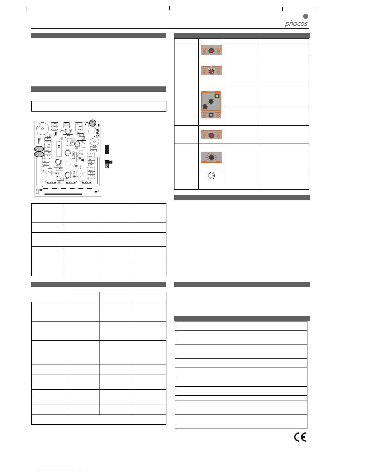
Controlador de Carga Solar CML05-2, CML08-2, CML10-2, CML15-2, CML20
Manual do Usuário Português, Página 2
Função Desconectar Baixa Voltagem (LVD)
O
controlador possui 2 modalidades diferentes para proteger a bateria de ser
p
rofundamente descarregada:
1. Desconectar a 11,4 V (na corrente eléctrica nominal) até 11,9 V (sem corrente
eléctrica). Modalidade de operação normal para protecção da bateria.
2
. Voltagem controlada: Desconectar a 11,0 V sendo isto fixo no controlo.
A
dequado quando as cargas do circuito secundário vêm directamente da bateria.
O controlador é pré-ajustado na fábrica à Modalidade 1. Veja abaixo a descrição para
mudança no ajuste de controlo de modalidade.
Em caso de dúvida com relação à modalidade a ser usada, consulte o revendedor pois
i
sto deve ser avaliado dependendo da bateria usada.
Ajustes de Controlo
O
controlador pode ser configurado para operação especial. Para este fim, retire os
parafusos na parte de trás do controlador e abra o invólucro.
AVISO: O controlador não deve ser aberto quando conectado ou durante
o
peração!
Quando o controlador for aberto, há 3 ligações em ponte no painel electrónico:
P
ara efectuar mudanças, coloque a
l
igação em ponte em ambos os pinos
de contacto ou apenas em um pino de
contacto:
Ligação em ponte fechada
1
3
2
Aberta
ligação em ponte
Com estas ligações em ponte os seguintes ajustes podem ser configurados:
Ligação em
ponte
GEL (1) LVD -
Desconectar
Baixa voltagem
(2)
Alarme (3)
Função Tipo de Bateria
Função Desconectar
Baixa Voltagem
Sinal de alarme
acústico
Ajuste de Controlo
ligação em ponte
aberta
Electrólito líquido
(bateria fechada)
Estado da Carga
controlado
Alarme desligado
Ajuste de Controlo
ligação em ponte
fechada
GEL (bateria fechada)
Voltagem controlada Alarme ligado
Ajuste de controlo
operacional
Ligação em ponte
aberta (electrólito
líquido)
Ligação em ponte
aberta estado-dacarga controlado
Ligação em ponte
fechada
Alarme ligado
Após completar o ajuste de controlo, repor o invólucro e segure-o com os parafusos.
Recursos de Segurança
O controlador é protegido contra instalação ou uso incorrectos:
No terminal solar
No terminal da
bateria
No terminal de
carga
conectada com
polaridade correcta
Sem restrição Operação normal Sem restrição
Bateria conectada
com polaridade e
rrada
Sem restrição
Sem restrição. Aviso
Acústico
Sem restrição
Polaridade Reversa
Sim, não no sistema
de voltagem de
24V.
Sim, apenas se a
bateria estiver
conectada. Aviso
Acústico
Saída de carga está
protegida.
Dispositivos podem
ser danificados.
Curto-circuito Sem restrição
Sem restrição.
CUIDADO: A
bateria deve ser
protegida por um
fusível.
Sem restrição
Sobreintensidade Sem protecção -----------------------
Controlador desliga
o terminal de carga.
Sobrecarga Térmica Sem protecção -----------------------
Controlador desliga
o terminal de carga.
Não há conexão Sem restrição Sem restrição Sem restrição
Corrente Reversa Sem restrição ----------------------- -----------------------
Sobrevoltagem Varistor 56 V, 2,3 J Máx. 40 V
Controlador desliga
o terminal de carga.
Subvoltagem Operação normal
Controlador desliga
o terminal de carga.
Controlador desliga
o terminal de carga.
AVISO: A combinação de diferentes condições de erros pode danificar o
controlador. Sempre remova um erro antes de continuar a conectar o controlador!
Descrição de Erro
E
rro Mostrador Razão Solução
Bateria está com
c
arga baixa.
Carga será reconectada
assim que a bateria for
recarregada.
S
obreintensidade/
Curto-circuito dos
dispositivos
Desligue todos os
dispositivos. Remova o
curto-circuito. O
c
ontrolador ligará a carga
a
utomaticamente após máx.
1 minuto.
Voltagem da bateria
a
lta demais (>15,5 /
3
1,0 V)
V
erifique se outras fontes
sobrecarregam a bateria. Se
não, o controlador está
danificado.
Dispositivos
n
ão são
fornecidos
Os fios ou o fusível
d
a bateria estão
d
anificados, a bateria
tem resistência alta.
V
erifique a bateria, os fios e
o
s fusíveis da bateria.
A
bateria
está vazia
após um
tempo curto
A bateria está com
baixa capacidade
Troque a bateria
A bateria
não está
sendo
carregada
d
urante o
dia
solar defeituoso ou
polaridade errada
c
onexão defeituosa/
polaridade reversa
Polaridade
errada da
b
ateria
Som
p
ermanente
A bateria está
conectada com
p
olaridade reversa
Remova a polaridade
reversa
Recomendações Gerais de Segurança e Uso
Uso Intencionado
O controlador de cargas é intencionado exclusivamente para uso em sistemas
fotovoltaicos com voltagem nominal de 12 V ou 24 V e apenas em conjunção com
baterias ácidas de chumbo ventiladas ou seladas (VRLA).
Recomendações de Segurança
As baterias armazenam uma grande quantidade de energia. Não curto-circuitar a
bateria sob circunstância alguma. Nós recomendamos conectar um fusível (do tipo
lento, conforme a corrente nominal do controlador) directamente ao terminal da
bateria.
Baterias podem produzir gases inflamáveis. Evite faíscas, uso de fogo ou qualquer
chama desprotegida. Certifique-se que o cómodo da bateria é ventilado.
Evite tocar os fios ou terminais, ou causá-los curto-circuitos. Note que as voltagens
nos terminais ou fios específicos podem ser até o dobro da voltagem da bateria.
Utilize ferramentas isoladas, mantenha-se em solo seco e mantenha as mãos secas.
Mantenha as baterias e o controlador de carga fora do alcance de crianças.
Observe as recomendações de segurança do fabricante da bateria. Quando em
dúvida, consulte o revendedor ou instalador.
Exclusão de Responsabilidade
O fabricante não será responsável por danos, especialmente na bateria, causados por
uso além dos intencionados ou mencionados neste manual ou se as recomendações
do fabricante da bateria não forem observadas. O fabricante não será responsável
caso algum serviço ou conserto seja executado por pessoas não autorizadas, por uso
impróprio, instalação incorrecta, ou design malfeito de sistema.
Dados técnicos
Voltagem nominal 12 / 24 V, reconhecimento automático
Voltagem de Reforço 14,5 / 29,0 V (25°C), 2 h
Voltagem de
Equalização
14,8 / 29,6 V (25°C), 2 h
Voltagem Flutuante 13,7 / 27,4 V (25°C)
Função Desconectar
Baixa Voltagem
11,4-11,9 / 22,8-23,8 V controlado pelo Estado da
Carga
11,0 / 22,0 V controlado pela voltagem
Voltagem para
Reconexão da carga
12,8 / 25,6 V
Compensação da
temperatura
-4 mV/célula*K
Máx. carga do painel
solar
5 / 8 / 10 / 15 / 20 A conforme o modelo número @
50°C
Máx. carga eléctrica 5 / 8 / 10 / 15 / 20 A conforme o modelo número @
50°C
Dimensões 80 x 100 x 32 mm (larg. x alt. x prof.)
Peso 180 g
Máx. tamanho do fio 16 mm² (AWG - escala americana normalizada #6)
Consumo próprio 4 mA
Variação da
temperatura ambiente
-25 a + 50 °C
Invólucro de protecção IP 20
Sujeito a mudanças sem notificação. Versão: CML041214
Fabricado em um dos seguintes países: Alemanha – China – Bolívia - Índia
Phocos AG – Alemanha www.phocos.com
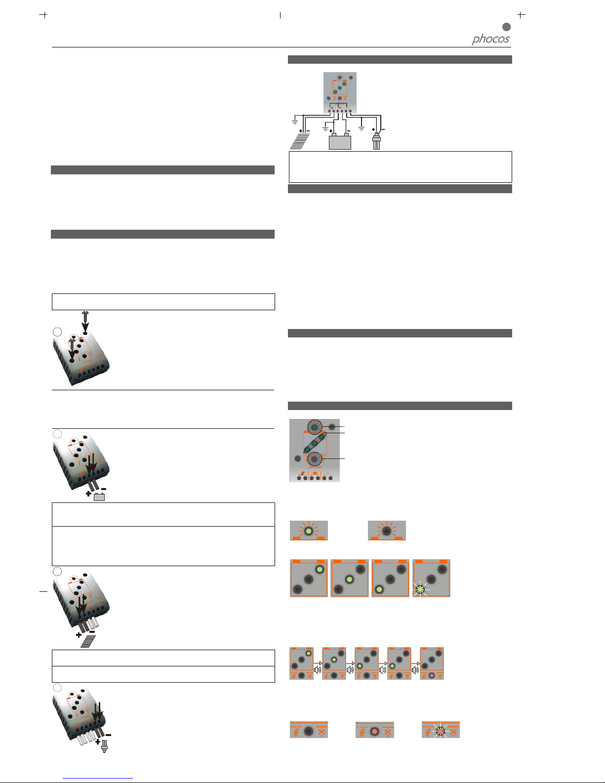
Regolatore di carica solare CML05-2, CML08-2, CML10-2, CML15-2, CML20
Manuale per l'utente, Italiano, Pagina 1
G
entile Cliente,
La ringraziamo per aver acquistato un prodotto Phocos. Con il regolatore CML, lei
dispone di un dispositivo di avanzata tecnologia, sviluppato secondo i più recenti standard tecnici oggi disponibili. È dotato di una serie di straordinarie caratteristiche, quali:
Visualizzazione chiara e leggibile dello stato di carica
Segnale acustico quando cambia lo stato di carica
Disinserimento a bassa tensione regolato in base allo stato di carica o alla tensione
Morsetti del connettore da 16 mm²
Completa protezione elettronica
Questo manuale fornisce raccomandazioni importanti per l'installazione, l'utilizzo e la
programmazione del regolatore ed anche soluzioni concrete nel caso si verificassero
p
roblemi. Nel vostro interesse, vi consigliamo di leggere attentamente questo manuale
e
di attenervi alle raccomandazioni per l'uso e per la sicurezza che troverete nell'ulti-
ma parte di questo.
Descrizione delle funzioni
Il regolatore di carica protegge la batteria dal rischio di sovraccarico da parte
dell'impianto solare e da quello di venir scaricata gravemente da parte dei carichi.
Le caratteristiche di carica comprendono diversi stadi che includono l'adattamento
a
utomatico alla temperatura dell'ambiente.
Il regolatore di carica si regola automaticamente su una tensione impianto di 12 V o
24 V .
Il regolatore di carica dispone di varie funzioni di sicurezza e di visualizzazione.
Montaggio e collegamento
È previsto l'uso del regolatore esclusivamente per interno. Proteggetelo dalla luce
s
olare diretta e ponetelo in un ambiente asciutto. Non installatelo mai in stanze umide
(come i bagni).
Il regolatore misura la temperatura ambientale per determinare la tensione di carica.
Regolatore e batteria devono essere installati nella stessa stanza.
I
l regolatore si scalda quando è in funzione e dovrebbe quindi venir installato esclusi-
vamente su superfici non infiammabili.
N
OTA: seguite le operazioni sottoindicate per collegare il regolatore, onde evitare
e
rrori di installazione.
1
F
issate il regolatore al muro con viti che siano appropriate al
materiale dello stesso. Utilizzate viti con diametro massimo del
gambo di 4 mm e 8 mm della testa, non coniche. Tenete
presente che le viti devono sostenere anche la forza derivante
dal sistema dei cavi.
Assicuratevi che le fessure sui lati del ventilatore non siano
ostruite.
Una placca di montaggio a scorrimento a norma di legge è disp
onibile come accessorio
(CX-DR2). Questo permette di montare il regolatore su un binario standard da 35
mm. a norma di legge. Rimuovete le viti dalla parte posteriore del regolatore ed
avvitate la placca di montaggio con la vite di fissaggio (lunga) sulla parte posteriore del
regolatore.
2
Collegate i cavi che conducono alla batteria con la polarità
corretta. Per evitare tensione sui cavi, collegate innanzitutto il
regolatore, poi la batteria. Attenetevi alla lunghezza del cavo
raccomandata (min. 30 cm. fino ad un massimo approssimativamente di 100 cm.) e alla grandezza del cavo:
CML05: min. 2,5 mm², CLM08: min. 4 mm²
CML10: min. 6 mm², CML15: CML20: min. 10 mm²
Una polarità sbagliata provocherà un suono di avvertimento
permanente.
AVVERTENZA: se la batteria è collegata con polarità invertita, anche i morsetti del
carico presenteranno polarità sbagliata. Non collegare mai carichi in queste condizioni!
NOTA: tenete presenti le raccomandazioni del produttore della vostra batteria. Vi
sconsigliamo vivamente di collegare un fusibile direttamente alla batteria per prevenire
qualsiasi cortocircuito ai cavi della batteria. Il fusibile deve prendere la corrente nominale del regolatore di carica:
CML05: 20A, CML08: 20A, CML10: 30A, CML15: 30A, CML20: 40A
3
Collegate i cavi che conducono all'impianto solare con la
polarità corretta. Per evitare qualsiasi tensione sui cavi, collegate
innanzitutto il regolatore, poi l'impianto solare. Attenetevi alla
grandezza del cavo raccomandata:
CML05: min. 2,5 mm²
CLM08: min. 4 mm²
CML10: min. 6 mm²
CML15, CML20: min. 10 mm²
NOTA: mettete il cavo positivo e quello negativo vicini l'uno all'altro per ridurre al
minimo gli effetti elettromagnetici.
NOTA: i pannelli solari generano tensione non appena esposti alla luce solare. Attene-
tevi, in ogni caso, alle raccomandazioni dei produttori del pannello solare.
4
Collegate i cavi che conducono ai carichi con la polarità
corretta. Per evitare tensione sui cavi, collegate innanzitutto il
cavo al carico, poi al regolatore. Attenetevi alla grandezza del
cavo raccomandata:
CML05: min. 2,5 mm²
CLM08: min. 4 mm²
CML10: min. 6 mm²
CML15, CML20: min. 10 mm²
Messa a terra dell'Impianto solare
Fate attenzione, poiché i morsetti positivi del
regolatore CML sono collegati interna
mente ed
hanno quindi lo stesso potenziale elettri
co. Se è
necessario effettuare una messa a terra, fatelo
s
empre sui cavi positivi.
N
OTA: se il dispositivo è utilizzato in un veicolo che ha il polo negativo della batteria
sul telaio, i carichi collegati al regola
tore non devono essere collegati elettricamente alla
carrozzeria della macchina, altrimenti le funzioni Disinserimento a bassa tensione e
quelle del fusibile elettronico andranno in cortocircuito.
Avviare il Regolatore
A
utoverifica
N
on appena il regolatore riceve corrente, proveniente dalla batteria o dall'impianto
solare, esso avvia una procedura di autoverifica. Poi la visualizzazione cambia su
funzionamento normale.
T
ensione impianto
I
l regolatore si sistema automaticamente su una tensione impianto di 12 V o 24 V.
Non appena la tensione al momento dell'avvio supera 20,0 V, il regolatore lo assume
come un impianto a 24 V.
S
e, all'avvio, la tensione della batteria non si trova all'interno del normale intervallo
o
perativo (da 12 a 15,5 V circa, oppure da 24 a 31 V circa), appare una visualizzazione
di stato, secondo la sezione DESCRIZIONE ERRORE.
T
ipo di batteria
I
l regolatore è preimpostato per operare con batterie al piombo con elettrolito
liquido. Se intendete utilizzare una batteria al piombo con elettrolito solido (tipo 'gel'
o tipo 'lanugine'), potete regolare le caratteristiche di carica (vedere "Impostazioni").
La carica di equalizzazione viene quindi disattivata.
Per qualsiasi dubbio, rivolgetevi al vostro rivenditore.
Raccomandazioni per l'uso
I
l regolatore si scalda durante il normale funzionamento.
Il regolatore non ha bisogno di alcuna manutenzione o servizio di assistenza. Togliete
la polvere con un panno asciutto.
È importante che la batteria venga completamente caricata di frequente (almeno una
volta al mese). In caso contrario, la batteria verrà danneggiata in maniera permanente.
Una batteria può venir caricata completamente solo se non viene utilizzata una
quantità eccessiva di energia in fase di carica. Tenetelo presente, in particolar modo
qualora installiate carichi aggiuntivi.
Funzioni di visualizzazione
Il regolatore è dotato di 5 LED e di un segnale di avvertimento acustico.
Visualizzazione di carica
Visualizzazione dello stato di
carica
Visualizzazione dello stato del
carico
Nel normale funzionamento, il regolatore mostra lo stato di carica della batteria e la
carica proveniente dai pannelli solari. Qualsiasi variazione dello stato di carica (SOC)
ad uno stato inferiore, viene segnalata anche acusticamente.
Visualizzazione di carica
L'impianto solare fornisce elettricità L'impianto solare non fornisce elettricità
Visualizzazione dello stato di carica
>75% 25-75% <25% lampeggia: <10%
La percentuale corrisponde all'energia disponibile fino a Disinserimento a bassa
tensione, relativamente ad una batteria completamente carica.
Segnali acustici
Una variazione dello stato di carica (SOC) ad uno stato inferiore, viene indicata da un
segnale acustico.
1x
3x
5x
25x
I carichi vengono disinseriti approssimativamente 1 minuto dopo una serie di 25
segnali.
Visualizzazione dello stato del carico
In caso di scarica quasi totale, oppure di sovraccarico/cortocircuito del carico, l'output
del carico è spento. Questo è indicato da:
Funzionamento normale Disinserimento a Sovraccarico o
bassa tensione Cortocircuito del carico

Regolatore di carica solare CML05-2, CML08-2, CML10-2, CML15-2, CML20
Manuale per l'utente, Italiano, Pagina 2
Funzione Disinserimento a bassa tensione (LVD)
I
l regolatore dispone di 2 diverse modalità, per prevenire che la batteria venga scarica-
t
a in maniera grave:
1. Stato di carica controllato: Disinserisci a 11,4 V (a corrente di carico nominale)
fino a 11,9 V (a corrente a vuoto). Modalità operativa normale per una buona
protezione della batteria.
2
. Tensione controllata: Disinserimento all'impostazione prestabilita di 11,0 V.
Appropriato se i carichi di derivazione prendono corrente direttamente dalla batteria.
Il regolatore è preimpostato in Modalità 1 alla fabbricazione. Viene descritto di seguito
c
ome cambiare l'impostazione delle modalità.
In caso di dubbio su quale modalità scegliere, consultate il vostro rivenditore, poiché
questa variabile deve essere valutata in base alla batteria utilizzata.
Impostazioni
Il regolatore può venir configurato per speciali operazioni. A questo scopo, aprite il
coperchio del regolatore togliendo le viti dalla parte posteriore.
A
VVERTENZA: il regolatore non deve venir aperto quando è collegato ed è in
funzione!
Quando il regolatore è aperto, sono visibili 3 ponti sulla scheda elettronica:
per cambiare, mettete il ponte su
entrambi i piedini di contatto oppure
solamente su un piedino di contatto:
P
onte chiuso
1
3
2
Ponte
a
perto
C
on questi ponti, si possono configurare le seguenti impostazioni:
Ponte GEL (1) LVD (2) BUZ (3)
Funzione Tipo di batteria
n-
one
Segnale d'allarme
acustico
Impostazione
ponte aperto
Elettrolito liquido
(batteria chiusa)
Stato di carica controllato
Allarme spento
Impostazione
ponte chiuso
GEL (batteria chiusa) Tensione controllata Allarme acceso
Impostazione
operativa
Ponte aperto (elet-
trolito liquido)
Ponte aperto stato di
carica controllato
Ponte chiuso
Allarme acceso
Dopo aver completato l'impostazione, riposizionate il coperchio e fermatelo con le
viti.
Caratteristiche di sicurezza
Il regolatore è protetto da installazioni o utilizzi errati:
Al morsetto del
solare
Al morsetto della
batteria
Al morsetto del carico
collegata con
polarità corretta
Non limitato
Funzionamento
normale
Non limitato
Batteria collegata
con polarità errata
Non limitato
Non limitato.
Avvertimento
acustico
Non limitato
Polarità invertita
Sì, non a tensione
impianto di 24V.
Sì, se solo la batteria
è collegata. Avver-
time
nto acustico
L'output del carico è
protetto. I carichi
possono essere danneggiati.
Cortocircuito Non limitato
Non limitato.
ATTENZIONE: la
batteria deve essere
protetta dal fusibile.
Non limitato
Sovracorrente Nessuna protezione -----------------------
Il regolatore spegne il
morsetto del carico.
Sovraccarico
term
ico
Nessuna protezione
-----------------------
Il regolatore spegne il
morsetto del carico.
Nessun collegamento
Non limitato Non limitato Non limitato
Corrente invertita Non limitato ----------------------- -----------------------
Sovratensione Varistore 56 V, 2,3 J Grandezza 40 V
Il regolatore spegne il
morsetto del carico.
Tensione al di sotto
del valore normale
Funzionamento
normale
Il regolatore spegne
il morsetto del
carico.
Il regolatore spegne il
morsetto del carico.
AVVERTENZA: la combinazione di diverse condizioni di errore può provocare
danni al regolatore. Eliminate sempre l'errore prima di continuare a collegare il
regolatore!
Descrizione errore
Errore
V
isualizza-
z
ione
Causa Soluzione
La batteria è bassa
Il carico si ricollegherà non
a
ppena la batteria sarà
r
icaricata.
Sovracorrente/
C
ortocircuito dei
c
arichi
Spegnere tutti i carichi.
Rimuovere cortocircuito. Il
r
egolatore accenderà il
carico automaticamente al
massimo dopo 1 minuto.
Tensione batteria
troppo alta (>15,5 /
3
1,0 V)
C
ontrollate se altre fonti
sovraccaricano la batteria.
In caso contrario, il
regolatore è danneggiato.
I carichi non
sono alimentati
Cavi della batteria o
fusibile della batteria
d
anneggiati, la
b
atteria presenta alta
resistenza
Controllare cavi della
batteria, fusibili e batteria.
L
a batteria si
s
vuota rapida-
mente
La batteria presenta
bassa capacità
C
ambiare batteria
L
a batteria non
si ricarica
durante il
giorno
solare difettoso o
polarità errata
collegamento difettoso/polarità invertita
Polarità della
batteria errata
S
uono
permanente
L
a batteria è collegata con polarità
invertita
Rimuovere polarità
invertita
Raccomandazioni generali per la sicurezza e per l'uso
Uso previsto
L'uso del regolatore di carica è previsto esclusivamente in impianti fotovoltaici con
tensione nominale di 12 V o 24 V ed esclusivamente in associazione con batterie al
p
iombo aperte o sigillate (VRLA).
Raccomandazioni per la sicurezza
Le batterie immagazzinano una grande quantità di energia. Non cortocircuitare mai
u
na batteria, in nessun caso. Raccomandiamo di collegare un fusibile (il tipo ad effetto lento, in base alla corrente nominale del regolatore) direttamente al morsetto
della batteria.
Le batterie possono produrre gas infiammabili. Evitate di provocare scintille, facendo
uso di fuoco o di altro tipo di fiamma libera. Assicuratevi che la stanza in cui si trova
la batteria sia ventilata.
Evitate di toccare o di cortocircuitare cavi o morsetti. Tenete presente che le
tensioni su morsetti o cavi specifici possono raggiungere il doppio della tensione
della batteria. Utilizzate attrezzi isolati, controllate che il pavimento su cui vi trovate
sia asciutto e fate in modo che le vostre mani siano sempre asciutte.
Tenete i bambini lontani dalle batterie e dal regolatore di carica.
Vi preghiamo di osservare le raccomandazioni per la sicurezza da parte del produt-
tore della batteria. Qualora aveste dubbi, fate riferimento al vostro rivenditore o a
chi vi ha installato il regolatore.
Esclusione di responsabilità
Il produttore non sarà da ritenersi responsabile per danni, specialmente alla batteria,
provocati da un uso diverso da quello previsto o dall'uso menzionato in questo
manuale, oppure qualora le raccomandazioni del produttore della batteria non
vengano rispettate. Il produttore non sarà da ritenersi responsabile qualora siano state
effettuate riparazioni o servizio di assistenza da parte di personale non autorizzato,
l'uso sia stato diverso da quello previsto, l'installazione sia stata effettuata in maniera
errata o l'impianto sia stato progettato male.
Dati tecnici
Tensione nominale 12 / 24 V, riconoscimento automatico
Aumento tensione 14,5 / 29,0 V (25°C), 2 h
Equalizzazione tensione 14,8 / 29,6 V (25°C), 2 h
Stabilizzazione tensione 13,7 / 27,4 V (25°C)
Funzione Disinserimento a
bassa tensione
11,4-11,9 / 22,8-23,8 V controllato per stato di carica
11,0 / 22,0 V controllato per tensione
Tensione ricollegamento
carico
12,8 / 25,6 V
Compensazione temperatura
-4 mV/cell*K
Grandezza massima del
pannello solare
5 / 8 / 10 / 15 / 20 A in base al numero di modello a
50°C
Grandezza massima del
carico
5 / 8 / 10 / 15 / 20 A in base al numero di modello a
50°C
Dimensioni 80 x 100 x 32 mm (largh. x alt. x prof.)
Peso 180 gr.
Grandezza massima del
cavo
16 mm² (AWG #6)
Autoconsumo 4 mA
Intervallo temperatura
ambiente
da -25 a + 50 °C
Classe di protezione IP 20
Soggetto a modifica senza preavviso. Versione: CML041214
Fabbricato in uno dei seguenti paesi: Germania – Cina – Bolivia - India
Phocos AG – Germany www.phocos.com
 Loading...