

PHINX PASRW080-V, PASRW050SB-VTD, PASRW060SB-VTD, PASRW060-V, PASRW080SB-VTD Installation And Instruction Manual
...
Installation and Instruction Manual
Air Source Water Chiller and Heat Pump
Floor heating and Air-con Unit (with Super Heater)
This is for: PASRW050(SB)-V(-TD)
PASRW060(SB)-V(-TD)
PASRW080(SB)-V(-TD)
PASRW100S(B)-V(-TD)
PASRW130S(B)-V(-TD)

CONTENT
1 Preface
1
3 Specification
5
(3) Specification data
6
(4) Unit Dimension
7
8
4 Installation
9
12
5 Usage
7 Appendix
24
18
19
18
22
2 Safety Precaution
2
(1) Mark notes
2
(2) Icon Notes
2
(3) Warning
3
25
26
28
(1) Nomenclature of the heat pump
(2) Appearance and Structure of the unit
5
5
8
9
9
10
10
11
11
12
15
21
21
23
23
10
(1) Application of heat pump
(2) Choose a right heat pump unit
(3) Installation place
(4) Installation method
(5) Water loop connection
(6) Power supply connection
(7) Location of the unit
(8) Transit
(9) Trial Running
(1) The displaying of the wire controller
(2) Installation of remote controller
6 Maintenance
(2) Ordinary malfunctions and solution
(1) Maintenance
(1) Appendix 1
(2) Appendix 2
(3) Appendix 3
(4) Appendix 4
(5) Appendix 5
(6) Appendix 6
(7) Appendix 7
(8) Appendix 8
(4) Attention
4
(3) Symbol meaning
16
(4) Functions associated with the buttons
17
4 Quiet running
High quality and efficient compressor, fan and water pump is used to ensure the lo w
noise level with insulation.
5 Good heat exchange rate
The heat pump unit use special designed heat exchanger to enhance whole efficiency.
The unit must be installed by qualified personnel.
Failure to comply with these recommendations will invalidate the warranty.
2 Nice appearance
The heat pump is designed with beautiful looking. The monobloc one has the water
pump included which is very easy for installation.
3 Flexible installation
The unit has smart structure with compact body, just simple outdoor installation is needed.
This series of heat pump unit owns following features:
1 Advanced controlling
The PC microcomputer based controller is available for the users to review or set the
running parameters of the heat pump. Centralized co ntrolling system can control several
units by PC.
It is vital that the below instructions are adhered to at all times to k eep the warranty.
6 Large working range
This series of heat pump is designed to work under different working conditions as low
as -15 degrees for heating.
Preface

1
The manufacture of this product will not be held responsible if someone is injured or
the unit is damaged, as a result of improper installati on, debugging, unnecessary
maintenance which is not in line with this man ual.
This manual includes all the necessary inf ormation about installation, debugging,
discharging and maintenance. Please re ad this manual carefully before you open or
maintain the unit.
4 Quiet running
High quality and efficient compressor, fan and water pump is used to ensure the lo w
noise level with insulation.
5 Good heat exchange rate
The heat pump unit use special designed heat exchanger to enhance whole efficiency.
The unit must be installed by qualified personnel.
—The unit can only be opened or repaired by qualified installer or an authorised dealer.
—Use genuine standard spare parts only.
—Maintenance and operation must be carrie d out according to the recommended time and
frequency, as stated in this manual.
Failure to comply with these recommendations will invalidate the warranty.
2 Nice appearance
The heat pump is designed with beautiful looking. The monobloc one has the water
pump included which is very easy for installation.
3 Flexible installation
The unit has smart structure with compact body, just simple outdoor installation is needed.
This series of heat pump unit owns following features:
1 Advanced controlling
The PC microcomputer based controller is available for the users to review or s et the
running parameters of the heat pump. Centralized co ntrolling system can control several
units by PC.
It is vital that the below instructions are adhered to at a ll times to keep the warranty.
Air source water chiller and heat pump is a kind o f high efficiency, energy saving and
environment friendly equipment, whic h is mainly used for house warming. It can work with
any kind of indoor unit such fan coil, radiato r, or floor heating pipe, by provide warm or hot
water. One unit of monobloc heat pump can also wo rk with several indoor units.
The air source water heat pump unit is designe d to have heat recovery by using super
heater which can provide hot water for sanit ary purpose.
6 Large working range
This series of heat pump is designed to work under different working conditions as low
as -15 degrees for heating.
In order to provide the customers with high quality, strong reliability and good versatility
product, this heat pump is produced by strict design an d manufacture standards.
Preface

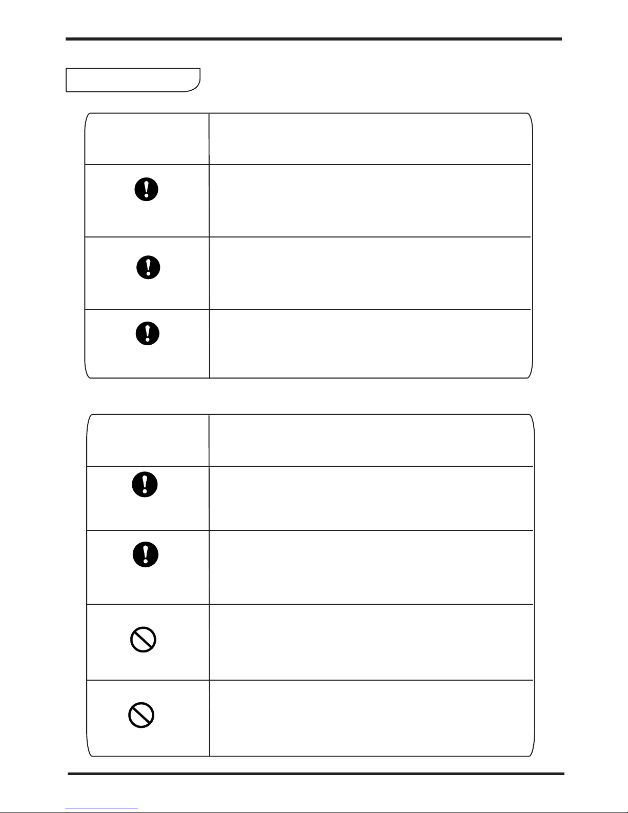
Mark
Icon
Meaning
Meaning
A wrong operation may lead to death or heavy injury on people.
A wrong operation may lead to harm on people or loss of material.
Prohibition. What is prohibited will be nearby this icon
Compulsory implement. The listed action need to be taken.
ATTENTION (include WARNING)
Please pay attention to what is indicated.
Mark Notes
Icon notes
WARNING
ATTENTION
To prevent the users and others from the harm of this unit, and avoid damage
on the unit or other property, and use the heat pump properly, please read this
manual carefully and understand the following information correctly.
Safety Precaution
Safety Precaution

安装前注意事项
The heat pump must be installed by qualified personals,
to avoid improper installation which can lead to water
leakage, electrical shock or fire.
Please make sure that the unit and power connection
have good earthing, otherwise may cause electrical shock.
Installation
Professional installer
is required.
Earthing is required
Warning
Safety Precaution
Meaning
Operation
Meaning
PROHIBITION
Shut off the power
DO NOT put fingers or others into the fans and evaporator
of the unit, otherwise harm may be occurred.
When there is something wrong or strange smell, the power
supply need to be shut off to stop the unit. Continue to run
may cause electrical short or fire.
Move and repair
Entrust
Prohibit
Entrust
When the heat pump need to be moved or installed again,
please entrust dealer or qualified person to carry it out.
Improper installation will lead to water leakage, electrical
shock, injury or fire.
It is prohibited to repair the unit by the user himself, otherwise
electrical shock or fire may be occur.
When the heat pump need to be repaired, please entrust
dealer or qualified person to carry it out. Improper movement
or repair on the unit will lead to water leakage, electrical
shock, injury or fire.
Meaning
32
Switch off
the power
Prohibition
Please switch off the power for clean or maintenance.
It is prohibited to use copper or iron as fuse. The right fuse
must be fixed by electrician for the heat pump.
It is prohibited to spray the flammable gas to the heat pump,
as it may cause fire.
Installation
Operation
Prohibition
安装前注意事项
ATTENTION
Check the
installation basement
Please check the installation basement in a period (one month),
to avoid any decline or damage on the basement, which may
hurt people or damage the unit
Safety Precaution
Meaning
Fix the unit
Installation Place
Need
circuit breaker
The unit CANNOT be installed near the flammable gas.
Once there is any leakage of the gas, fire can be occur.
Make sure that the basement of the heat pump is strong
enough, to avoid any decline or fall down of the unit
Make sure that there is circuit breaker for the unit, lack of
circuit breaker can lead to electrical shock or fire.
Meaning
Specification
1 Nomenclature of the heat pump
4

Specification
2 Appearance and structure of the unit:
1 Nomenclature of the heat pump
4: mode C--cooling only R--heating and cooling D--a ux-electrical heater
3: system loop X--gas loop S--water loop
6: capacity nominated cooling or heating capacity ( 3 figures,horsepower/10)
2: heat source A--air source W--water source
1: P--Product
5: outdoor unit type W--monobloc type F--split type
7: power supply (omit)--single phase power S--thr ee phase power
For example: PASCW060B-V stand for air source water chiller with 6 horsepower
cooling capacity(15kw) and with water pump
8: water pump (omit)-no water pump B--water pump included
9: Appendix V- the shape of condenser
P A S R W 050 S B- V- T D
1 2 3 4 5 6 7 8 9 10 11
Wire
controller
The maximum cable for
the wire controller is 200
metres from the heat pump.
10: water tank (omit)--no water tank T--water tank included
11: Auxiliary electrical heater (omit)--without auxiliary electrical heater
D--with auxiliary electrical heater
5

Specification
Unit Mo del
Cooli ng Ca pacit y
Heati ng Ca pacit y
Cooli ng Po wer Inp ut
Heati ng Po wer Input
Runni ng Cu rrent (Co oli ng/He ati ng)
Power S upp ly
Compr ess or Quantit y
Compr ess or
Fan Qua nti ty
Fan Pow er In put
Fan rot ate s peed
Noise
Wat er Pu mp Inpu t
Wat er he ad
Wat er Co nnect ion
Wat er Fl ow Volum e
Wat er Pr essur e Dro p
Unit Ne t Dim ensio ns( L/W /H)
Unit Sh ipp ing Dim ens ion s(L/W /H)
Net Weight
Shipp ing W eig ht
PASR W
kW
BTU/h
kW
BTU/h
kW
kW
A
V/Ph/ Hz
W
RPM
dB(A)
kW
m
inch
3
m / h
kPa
mm
mm
kg
kg
Cooling: temperature:35℃/24℃,Inter/outlet water temperature:12℃/7℃
Heating: tempe ra tu re :7℃/ 6℃,I nt er /outlet water temperature:30℃/35℃
Ambient
Ambient
(Above information just for your reference , Pl ea se s ub je ct t o na me pl at e on t he u ni t)
050(B )-V( -TD)
11.5
40000
15.0
52000
4.2
3.6
18.3/ 15. 7
230/1 /50
2
Rotar y
1
390×1
900
56
0.2
10
1
2.3
34
060S( B)-V (-TD)
13.5
46000
17.0
58000
4.9
4.1
8.4/7 .1
380/3 /50
1
Scrol l
1
390×1
900
56
0.2
10
1
2.8
34
060(B )-V (-TD)
13.5
46000
17.0
58000
4.7
4.1
20.4/ 17. 8
230/1 /50
2
Rotar y
1
390×1
900
56
0.2
10
1
2.8
34
Unit Mo del
Cooli ng Ca pacit y
Heati ng Ca pacit y
Cooli ng Po wer Inp ut
Heati ng Po wer Input
Runni ng Cu rrent (Co oli ng/He ati ng)
Power S upp ly
Compr ess or Quantit y
Compr ess or
Fan Qua nti ty
Fan Pow er In put
Fan rot ate s peed
Noise
Wat er Pu mp Inpu t
Wat er he ad
Wat er Co nnect ion
Wat er Fl ow Volum e
Wat er Pr essur e Dro p
Unit Ne t Dim ensio ns( L/W /H)
Unit Sh ipp ing Dim ens ion s(L/W /H)
Net Weight
Shipp ing W eig ht
PASR W
kW
BTU/h
kW
BTU/h
kW
kW
A
V/Ph/ Hz
W
RPM
dB(A)
kW
m
inch
3
m / h
kPa
mm
mm
kg
kg
080S( B)- V(-TD)
18.0
61500
23.0
78000
6.4
5.6
11.0 /9.7
380/3 /50
2
Scrol l
2
390×2
900
59
0.75
24
1.5
3.8
36
100S( B)- V(-TD)
22.5
76700
28.0
95500
8.6
6.8
14.8/ 11.7
380/3 /50
2
Scrol l
2
390×2
900
60
0.75
24
1.5
4.6
37
130S( B)- V(-TD)
25.5
87000
35.0
12000 0
10.2
8.5
17.6/ 14. 7
380/3 /50
2
Scrol l
2
390×2
900
60
0.75
24
1.5
5.8
38
080(B )-V (-TD)
18.0
61500
23.0
78000
6.4
5.6
27.8/ 24. 3
230/1 /50
2
Scrol l
2
390×2
900
59
0.75
24
1.5
3.8
36
050S( B)-V (-TD)
11.6
40000
15.0
52000
4.1
3.7
7.1/6 .4
380/3 /50
1
Scrol l
1
390×1
900
56
0.2
10
1
2.3
34
See the d raw ing of the uni ts
see pac kag e label
see nam epl ate
see pac kag e label
See the d raw ing of the uni ts
see pac kag e label
see nam epl ate
see pac kag e label
3. Specification data
Specification
4.Unit Dimension

Specification
Water inlet
Water outlet
Drainage
73
5
4
8
0
985
1015
1
130
3
With water tank
of the units
Without water tank
of the units
3
1
2
5
1
2
4
5
4
5
4
3
2
1
Sanitary hot water outlet
Sanitary hot water inlet
Remark:
7
3
5
48
0
985
1015
1
1
3
0
With water tank
of the units
Without water tank
of the units
Water inlet
Water outlet
Drainage
5
4
3
2
1
Sanitary hot water outlet
Sanitary hot water inlet
Remark:
3
3
1
2
5
1
2
4
5
4
4.Unit Dimension
Model:PASRW050/060(B)-V(-TD)
Model: PASRW050/060S(B)-V(-TD)
735
480
1464
1490
1130
With water tank
of the units
Without water tank
of the units
Water inlet
Water outlet
Drainage
5
4
3
2
1
Sanitary hot water outlet
Sanitary hot water inlet
Remark:
5
4
3
1
2
5
4
3
2
1
Model: PASRW080/100/130S(B)-V(-TD)
76

Installation
1 Application of heat pump
1.1 Only for air-con
WATER COUPLING
AUTOMATIC AIR VENT
CHECK-VALVE FOR WATER
FLEXIBLE CONNECTION FOR WATER
DIRTY DRAI N
WATER THERMOMETER
WATER PRESSURE METER
WATER FILTER
4 Installation method
2 Choose a right heat pump unit
2.1 Based on the local climate condition, co nstruction features and insulation level,
calculate the required cooling(heati ng) capacity per square meter.
2.2 Conclude the total capacity which will b e needed by the construction.
2.3 According to the total capacity needed, c hoose the right model by consulting the heat.
pump features as below:
Heat pump features
Cooling only unit: chilled water outlet tem p. at 5-15 , maximum ambient temp. at 43 .
Heating and Cooling unit:for cooling chilled water outlet temp. at 5-15 ,maximum
ambient temp. at 43 . For heating, warm water inlet temp. at 40-50 , minim um ambient
temp. at -10 .
Unit application
Air source water chiller and heat pump is used fo r house, office, hotel, and so forth, which
need heating or cooling separately, with each area need to be control led.
The unit can be installed on any place outdoor which can carry heavy mac hine such
as terrace, housetop, ground and so on.
3 Installation place
Installation

4 Installation method
The heat pump can be installed onto the concrete basement by expansi on screws, or
onto a steel frame with rubber feet which can be p laced on the ground or housetop.
Make sure that the unit is placed horizontal ly.
2 Choose a right heat pump unit
2.1 Based on the local climate condition, co nstruction features and insulation level,
calculate the required cooling(heati ng) capacity per square meter.
2.2 Conclude the total capacity which will b e needed by the construction.
2.3 According to the total capacity needed, c hoose the right model by consulting the heat.
pump features as below:
Heat pump features
Cooling only unit: chilled water outlet tem p. at 5-15 , maximum ambient temp. at 43 .
Heating and Cooling unit:for cooling chill ed water outlet temp. at 5-15 ,maximum
ambient temp. at 43 . For heating, warm water inlet temp. at 40-50 , minim um ambient
temp. at -10 .
℃ ℃
℃
℃ ℃
℃
Unit application
Air source water chiller and heat pump is used fo r house, office, hotel, and so forth, which
need heating or cooling separately, with each area need to be control led.
There must be enough space around the unit for maintenance.
The place is free from heat radiation and othe r fire flame.
There must be not obstacles near the air inlet a nd outlet of the heat pump.
A place which is free from strong air blowing.
There must be water channel around the heat pu mp to drain the condensing water .
The location must have good ventilation.
The unit can be installed on any place outdoor which can carry heavy mac hine such
as terrace, housetop, ground and so on.
A pall is needed in winter to protect the heat pump from snow.
3 Installation place
Installation
98

5 Water loop connection
Please pay attention to below matters when the water pipe is connected:
Try to reduce the resistance to the water from the piping.
The piping must be clear and free from dirty and b locks. Water leakage test must be
carried out to ensure there is no water leakin g. And then the insulation can be made.
Attention that the pipe must be tested by pressure separately. DO NOT test it together
with the heat pump.
The flow switch is installed inside of the hea t pump, check to ensure that the wiring and
action of the switch is normal and controlle d by the controller.
Try to avoid air stayed inside of the water pipe, and there must be air vent on the top
point of the water loop.
There must be thermometer and pressure met er at the water inlet and outlet, for easy
inspection during running.
There must be expansion tank on the top point of t he water loop, and the water level in
the tank must be at least 0.5 meter higher than the top point of the water loop.
6 Power supply connection
Open the front panel, and open the power supply access.
If the outside water pump is needed, please insert the power supply wire into the wire
access also and connect to the water pump term inals.
The power supply must go through the wire acce ss and be connected to the power
supply terminals in the controlling box. Then connect the 3-sign al wire plugs of the
wire controller and main controller.
If an additional auxiliary heater is need to be controlled by the heat pump controller,
the relay (or power) of the aux-heater must be c onnected to the relevant output of
the controller.
7 Location of the unit
A
B
Air inlet
Air outlet
C
Mai ntena nce
spa ce
Requirement:
A>500mm; B>500mm;
C>1000mm;D>500mm。
ATTENTION
wall
wall
wall
wall
Installation
Inl et wate r
Out let w ate r
Air inlet
D
Installation
9 Trial Running
8 Transit
When the unit need to be hung up during installa tion, a 8
meters cable is needed, and there must be soft material
between the cable and the unit to prevent dama ge to
the heat pump cabinet. (See picture 1)
DO NOT touch the heat exchanger of the heat pump with fingers or other objects!
10 11

Installation
Inspection before trial running
Check the indoor unit, and make sure that the pipe connection is right and the relevant
valves are open .
Check the heat pump unit including all of the sc rews and parts of the heat pump to see if
they are in good order. When power on, review the i ndicator on the controller to see if
there is any failure indication. The gas gauge can be connected to the check valve to
see the high pressure(or low pressure) of th e system during trial running.
Check the water loop, to ensure that the water inside of th e expansion tank is enough, the
water supply is good, the water loop is full of wa ter and without any air. Also make sure
there is good insulation for the water pipe.
Check the electrical wiring. Make sure tha t the power voltage is normal, the screws are
fastened, the wiring is made in line with the di agram, and the earthing is connected.
Trial running
Start the heat pump by press " " key on the controller. Check whether the water
pump is running, if it runs normally there wil l be 0.2 MPa on the water pressure meter.
When the water pump runs for 1 minutes, the compressor wi ll start. Hear whether there is
strange sound from the compressor. If abnormal sound occurs please stop the unit and
check the compressor. If the compressor runs well please look for the pressure meter
of the refrigerant.
9 Trial Running
Then check whether the power input and runni ng current is in line with the manual. If not
please stop and check.
Review whether the outlet water temperat ure is stable.
The parameters of the controller are set by the factory, it is not allowed to change then
by user himself.
Adjust the valves on the water loop, to make sure that the ho t(cool) water supply to each
door is good and meet the requirement of heati ng(or cooling).
8 Transit
When the unit need to be hung up during installa tion, a 8
meters cable is needed, and there must be soft material
between the cable and the unit to prevent dama ge to
the heat pump cabinet. (See picture 1)
WARNING
DO NOT touch the heat exchanger of the heat pump with fingers or other objects!
Picture 1
or
Usage
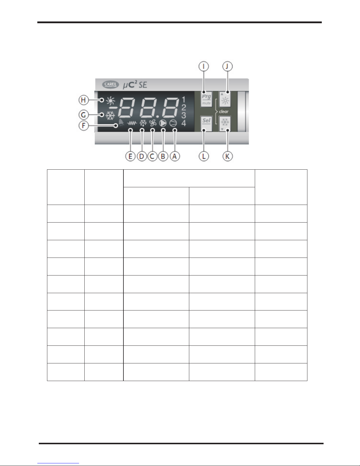
5.1 The displaying of the wire controller
Symbol
Colour
Meaning
Reference
refrigerant
circuit
1;2
3;4
A
B
C
D
E
F
G
H
Amber
Amber
Amber
Amber
Amber
Amber
Amber
Amber
Amber
Red
With LED ON With LED flashing
Compressor 1and/or
2ON
Compressor 3and/or
4ON
At least one
compressor ON
Pump ON
Condenser fan ON
Defrost active
Heater ON
Alarm active
Heat pump mode
Chiller mode
Start up request
Start up request
Start up request
Defrost request
Heat pump mode
request
Chiller mode request
1
2
1/2
1/2
1/2
1/2
1/2
1/2
1/2
1/2
Usage
2 Functions associated with the buttons
12

Usage
2 Functions associated with the buttons
Button
Unit status
Button press
I
L
I+L
J
K
J+K
L+J
Loading default values
Go up a sub-group inside the programming
area, until exiting (saving changes to EEPROM)
In the event of alarms, mute the buzzer
(if present) and deactivate the alarm relay
Access the direct parameters
Select item inside the programming area and
display value of direct parameters/conirm the
changes to the parameters
Program parameters afters entering password
Select top item inside the programming area
Increase value
Switch from standby to chiller mode (P6=1) and
vice versa
Provides immediate access to the condenser and
evaporator pressure and temperature probes and
DTE, DTC1-2
Select bottom item inside the programming area
Decrease value
Switch from standby to heat pump mode (P6=1)
and vice versa
Provides immediate access to the condenser
and evaporator pressure and temperature probes
and DTE, DTC1-2
Manual alarm reset
Mmediately reset the hour counter (inside the
programming area)
Force manual defrost on both circuits
Press at power ON
Press once
Press once
Press for 5s
Press once
Press for 5s
press once or press
and hold
press once or press
and hold
Press for 5s
Press once
press once or press
and hold
press once or press
and hold
Press for 5s
Press once
Press for 5s
Press for 5s
Press for 5s
13

Usage
3 Programming and saving the parameters
1
If you press“ ”,the unit will be heating mode;
If you press“ ”,the unit will be cooling mode;
[1]Start or stop unit
press“ ” lasts 3 seconds to start or stop unit, the
LED display as following:
or
[2]Check the setting data and amend the setting
2) press“ ” to go into parameter group.
1
1) press“ ” to go into data setting.
3)use“ ”and“ ”to select the
parameter group and then press“ ”.
4)use“ ”and“ ”to select the
parameter and then press“ ”.
5)after making the changes to the parameter,
press“ ”to confirm or “ ”to cancel the
changes.
6)Press“ ”to return to the previous menu
to save the modiications, press“ ”repeatedly
until reaching the main menu
1
Usage
5.2 Installation of remote controller
RJ12
Power supply
14

Usage
5.2 Installation of remote controller
(1)Connection
Telephone cable
Max.l.=40m
RJ12
Power supply
G0 G
G0
G
N F
24Vac 17VA
Fuse 250mA
Max.l.=250m
(min.cross-section
1.5mm2/AWG16)
RS485
twisted pair + shield
Rx/Tx+, Rx/Tx-, Gnd
Insert 120 ohm
terminal resistor
between Tx/Rx+
and Tx/Rx- for lines
longer than 20 m
To install the remote terminal, no
configuration is required on the UC2,
as the terminal works with any serial
address set for parameter H10.
Check, however, that is fitted with the
serial interface the Uc2 FCSER00000
.When first switched on the display
will show the. firmware version of the Uc2
After around 4 s the main screen will be
displayed, with the symbols that represent
he status of the Uc2.
1
15

Usage
Usage
In the event where the RS485 connection
is not performed correctly or the controller
is off, the terminal will clear the display and
show the message“OFFLINE”
Pressing the “Up”+“Down”+“Sel”
buttons together for more than 6 seconds
displays the“INFO”screen containing
information on the UC2 system and on the
communication.
Pressing the“Prg”button returns to the
main screen.
5.3 Symbol meaning
Symbol
Meaning
ON
Flashing
Refrigerant circuit
involved
1,2
3,4
Alarm button
red LED
Compressor 1
and/or 2 ON
Start request
1
2
Start request
Compressor 3
and/or 4 ON
At least one
compressor ON
1 and/or 2
1 and/or 2
1 and/or 2
1 and/or 2
1 and/or 2
1 and/or 2
1 and/or 2
1 and 2
1 and 2
Pump ON
Start request
Condenser fan ON
Start request
Defrost active
defrost request
Heater ON
Start request
Alarm active
EEPROM alarm
Alarm active
Warning relay
activated
Alarm relay active
Heat pump mode
(P6=1)
Chiller mode
(P6=1)
Season changeover
reques
Season changeover
reques
5.4 Functions associated with the buttons
16

Usage
5.4 Functions associated with the buttons
Press for 5 s
Button Button operationUnit status
Switch off buzzer or alarm relay,
if alarm active
Press once
Enter parameter programming mode
after entering password
Return to higher subgroup inside the
programming environment until
exiting, saving to EEPROM
Press once
Manual reset of alarms that are no
longer active
Press once
Select higher item inside the
programming environmen
Switch from standby to heat pump
mode (P6= 1) and vice-versa
Press once or
hold
Press for 5 s
Access direct parameters:selection
(as for button on Uc2)
Select item inside the programming
environment and display direct
parameter values/confirm the changes
to the parameter
Press for 5 s
Press once
Select lower item inside the
programming environmen
Switch from standby to chiller mode
(P6= 1) and vice-versa
+
Immediately reset the hour counter
(inside the programming environment)
Start manual defrost on both circuits
Display the terminal Info screen
Press once or
hold
Press for 5 s
Press for 5 s
Press for 5 s
Press for 6 s
17

1、Maintenance
Check the water supply and air vent frequently, to avoid lack of water or air in the water loop.
Clean the water filter in a certain period to keep good water quality. Lack of water and dirty
water can damage the unit. The heat pump will start the water pump per 72 hours when it is
not running, to avoid freezing.
Keep the unit in a place which is dry and clean, and h as good ventilation. Clean the heat
exchanger in 1 or 2 month and keep good heat excha nge rate and save energy.
Check each part of the unit and the pressure of the system. Replace the failure part if there
is any, and recharge the refrigerant if it is needed.
If the heat pump is not used for a long time, please drain out al l the water in the unit and
seal the unit to keep it good. Please drain the water from th e lowest point of the heat
exchanger to avoid freezing in winter. Water recharge and full inspection on the heat
pump is needed before it is restarted.
Check the power supply and the electrical sy stem, mak e sure the electrical components are
good, the wiring is well. If there is any part failed with wr ong action or smell, please replace
in time.
The water loop of the heat pump MUST be protected from freezing in winter time.Please
pay attention to below suggestions.Nonobservance on below suggestion will invalid the
warranty for the heat pump.
(1) Please do not shut off the power supply to the heat pump in winter. When the ai r
temperature is below 0 ℃, if the inlet water temperature is above 2 ℃ and b elow 4℃,
the water pump will start for freezing protect, if the inlet water is lower than 2 ℃, the
heat pump will run for heating.
(2) Use anti-freezing liquid (glycol water)
1) look for below table for the volume of the glycol water
2) the glycol water can be added into the system from the expansion ta nk of the water loop.
Note: if the glycol water is too much, the water flow and water pump will be influenced
and the heat exchange rate will be decreased. This table is for reference, please
use anti-freezing water according to the real condition of the local climate.
Please drain out the water in the super heater of the heat pu mp unit in winter, when the
super heater is not used.
50
-33
0.946
0.966
1.178
1.308
40
-22
0.961
0.976
1.121
1.263
30
-14
0.972
0.986
1.074
1.181
20
-8
0.982
0.992
1.040
1.129
10
-3
0.991
0.996
1.013
1.070
Glycol percentage (%)
ambient temp. (℃)
cooling/heating capacity fluctuati on
power input fluctuation
water flow fluctuation
water drop fluctuation
Maintenance
2.Ordinary malfunctions and solution
Maintenance
18 19

1) According to failure code of the controller,we can judge
and solute the failure.
2.Ordinary malfunctions and solution
Maintenance
malfunction
display
Water inlet temp.
Sensor failure
Evaporator sensor
failure
Anti freezing
under cooling mode
E1
E2
E3
tC1
Reason
The sensor is open
or short circuit
Check or change the sensor
resolution
Water flow rate
is not enough
Ambient temp. too low
Water outlet temp.
Sensor failure
The sensor is open
or short circuit
Check or change the sensor
The sensor is open
or short circuit
Check or change the sensor
Check the water flow volume,or
water system is jammed or not
The antifreezing
protection in winter
High pressure
protect
Check through each pressure
switch and return circuit
High pressure
switch action
Normal working
Flow switch failure
No water/little water
in water system.
Check the water flow volume,
water pump is failure or not
Low pressure
protect
Low pressure
switch action
Check through each pressure
switch and return circuit
Exhaust
temperature protect
HP1
LP1
FL
A1
A1
Exhaust temperature
is too high
Check through each temp.
switch and return circuit

2)、Look over and clear the failure according to below information.
Failure
Possible causes for the failure
Solutions
Heat pump
cannot
be starte d
1 Wrong p ower supp ly
2 power sup ply cable l oose
3 circuit b reaker op en
1 shut off the power a nd check po wer suppl y;
2 check pow er cable an d make righ t connect io n
3 check for t he cause an d replace t he fuse or
circuit b reaker
Wat er pump is
running w ith
high nois e or
without w ater
1 lack of wat er in the pip ing
2 much air in t he water lo op
3 water vav les close d
4 dirt and bl ock on the wa ter filte r
1 check the w ater supp ly and char ge water
to the pipi ng;
2 dischar ge the air in t he water lo op;
3 open the va lves in wat er loop;
4 clean the w ater filt er.
Heat pump
capacit y is low,
compres sor
do not stop
1 lack of ref rigeran t;
2 bad insul ation on wa ter pipe;
3 low heat ex change ra te on air sid e
exchang er;
4 lack of wat er flow
1 check for t he gas leak age and rec harge the
refrige rant;
2 make good i nsulati on on water p ipe;
3 clean the a ir side hea t exchang er;
4 clean the w ater filt er
High comp ressor
exhaust
1 too much re frigera nt
2 low heat ex change ra te on air sid e
exchang er
1 dischar ge the redu ndant gas
2 clean the a ir side hea t exchang er
Low press ure
problem
of the syst em
1 lack of gas
2 block on fi lter or cap illary
3 lack of wat er flow
1 check the g as leakag e and recha rge freon ;
2 replace f ilter or ca pillary ;
3 clean the w ater filt er and disc harge the a ir in
water loo p.
Compres sor do
not run
1 power sup ply failu re
2 compres sor conta ctor brok en
3 power cab le loose
4 protect ion on comp ressor
5 wrong set ting on ret urn water t emp.
6 lack of wat er flow
1 check off the powe r supply;
2 replace c ompress or contac tor;
3 tighten t he power ca ble;
4 check the c ompress or exhaus t temp.;
5 reset the r eturn wat er temp.;
6 clean the w ater filt er and disc harge the a ir i n
water loo p.
High nois e of
compres sor
1 liquid re frigera nt goes int o compres so r
2 compres sor failu re
1 bad evapo ration, c heck the ca use for bad
evapora tion and ge t rid of this ;
2 use new com pressor ;
Fan do not ru n
1 failure o n fan relay
2 fan motor b roken
1 replace t he fan rela y;
2 replace f an motor.
The compr essor
runs but he at
pump has no t
heating o r
cooling c apacity
1 no gas in the h eat pump;
2 heat exch anger bro ken;
3 compres sor failu re.
1 check sys tem leaka ge and rech arge refr ig erant ;
2 find out th e cause and r eplace th e heat
exchang er;
3 replace c ompress or.
Low outle t water
tempera ture
1 low water f low rate;
2 low setti ng for the de sired wat er temp.;
1 clean the w ater filt er and disc harge the a ir in
water loo p.
2 reset the d esired wa ter tempe rature.
Low water f low
protect ion
1 lack of wat er in the sys tem;
2 failure o n flow swit ch
1 clean the w ater filt er and disc harge the a ir in
water loo p.
2 replace t he flow swi tch.
Maintenance
Appendix 1 Install sketch map
Appendix
20

Especial installation( expandable water tank)
Appendix 1 Install sketch map
Appendix
Remark
1 main unit
2 fan coil
3 rubber flexible connection
4 thermometer
5 manometer
6 Y type filter
8 ball valve
10 bypass valve
1/2'
Technical request:
1.Each connection must be connected tightly and have no leakage.
2.the arrowhead orientation of automatic filled- water
must accord with water supply.
3.The pressure of automatic filled-water has been
set,and please do not remove screw.
autom ati c
fill- wat er
valve
Press ure
leaka ge
valve
2
1 4
1 5
1 3
1 7
Installation request:
1 The factory only offers main unit (1)in the legend, and the other modules
which are indispensable fittings, are provided by users or installation company.
2 The unit which of code contains the letter "B" ,has water pump inside and need
not install water pump outside (16)
3 Automatic ventilation(15)is installed on the top point of the water system。
4 The quantity proportion of two-way valve(13)and three-way valve(14)is
referred to the technical regulation, and there is three-way valve installed on the
farthest place of water system.
5 The ball valve (17) is used when it is swashed, filled water in the water system
and so on.
1
3
4
5
1 0
1 2
1 8
1 6
2 0
6
1 1
1 9
Conne ct supp ly pi pe
1/2'
inlet
outlet
8
11 drain valve
12 filter
13 two-way valve
14 three-way valve
15 automatic ventilation
16 water pump
17 ball valve
18 ball valve
19 expandable water tank
20 automatically filled-water
21

Appendix 2:
The installation explanation of automatic filled-water
1 When automatic filled-water valve is installed,the arrowhead orientation of inlet water must
accord with the orientation of valve ;
2 Automatic filled-water has been adjusted in advance to 1.5bar;
3 If readjust the pressure of inlet water,please operate as follows:
* open the screw cap(C);
* If reduce the pressure of water supply,pease unscrew the pressure to adjust the screw(B);
* If increese the pressure of waer supply,please screw down the pressure to adjust the screw (B)
4 When the system need fill water at first,wrest the handle(A) of filled-water.Then the handle(A)
can return(close) when the system is full of water.
5 Automatic filled-water Valve need clean in a periodic time and then you must close the tap,
unscrew the plug(D),remove the inside filter net.Please assemble them again after cleaning.
NOTICE: There are two connections for water pressure meter in the central section of
automatic filled-water,where the water pressure meter can be connected directly
and display the set pressure.The screw cap(C) must be tweaked after adjusting
the filled-water pressure.
B
C
1/4'
D
A
1/2'
Appendix
Appendix 3:
The installation explanation of the leakage pressure valve.
Appendix
Appendix 4:The way of assistant heat source connection
Unit provides the connection of assistant heat source which ca n not be only for gas-fired
boiler,but also for electronic boiler or warm-net pipe for city accordingly.
The way to the connection is as follows:
22

Appendix 3:
The installation explanation of the leakage pressure valve.
1 The action pressure of leakage pressure valve 'is more than 3bar(valve is open),
but the pressure can not be adjusted.
2 The valve will open automatically to make sure that the water loop of air-con system
is safe when the water pressure in the backwater side is higher than t he set pressure.
Appendix
Appendix 4:The way of assistant heat source connection
Unit provides the connection of assistant heat source which ca n not be only for gas-fired
boiler,but also for electronic boiler or wa rm-net pipe for city accordingly.
The way to the connection is as follows:
2)water chiller and heat pump+assistant el ectronic boiler
electro nic boile r
inlet
cable
water chiller and heat pump
gas-fir ed boiler
inlet
outlet
1) w ater chiller and heat pump+assistant gas-fired boiler
Three -wa y val ve
control w ire
outle t
water chiller and heat pump
inlet
cable
outle t
inlet
outlet
outlet
inlet
23

Appendix5、 The unit's parameter
Please set according the below table:
Appendix
Par
Description
Limits
Unit
R01
R02
R03
R04
12
2
40
2
℃
℃
℃
℃
Cooling set-point
Cooling differential
Heating set-point
Heating differential
Appendix
Appendix 6、Compensate temperature chart
Heating mode:
Cooling mode:
24

Appendix
15 20 25 30 35 40
45
50
55
22.1(20 )
19.6(17 .5)
17.1(15 )
14.6(12 .5)
12.1(10 )
9.6(7.5 )
7.1(5)
4.6(2.5 )
2.1(0)
0
2.5
5
A2
TgA2=-0.5
When the parameter set :
R01=20 R02=2 R03=30 R04=2
R17=-0.5 R18=20 R19=15 R20=20 R31=-0.8,
The compensate graphs in the heating and cooling mode are as follows:
-5
0
5 10 15 20
47.8(50 )
43.8(46 )
39.8(42 )
35.8(38 )
31.8(34 )
27.8(30 )
0
4
5
A1
TgA1=-0.8=R31
Appendix 6、Compensate temperature chart
Heating mode:
starting(stopping) temp.( C)
Ambient temp.( C)
Cooling mode:
Ambient temp.( C)
starting(stopping) temp.( C)
R19
R20
R03
R01
25

Appendix
Connections explanation:
1
2
3
4
No.
Symbol
Meaning
System1 mangtic valve outlet(220-230VAC)
System 2 economizer outlet temp.failure(input)
7
8
9
10
11
12
13
14
15
5
6
Ambient temp.(input)
RO02
RO04
RO03
RO01
AI03 GND
AI04 GND
AI05 GND
AI06 GND
AI07 GND
AI08 GND
AI09 GND
System 2 exhaust temp.(input)
System 1 exhaust temp.(input)
System 2 economizer inlet temp.failure(input)
System 1 economizer inlet temp.failure(input)
System 1 economizer outlet temp.failure(input)
Wire controller
System 2 economizer outlet temp.failure(input)
16
17
18
19
Ambient temp.(input)
NET GND 12V
DI01 GND
AI01 GND
AI02 GND
AI03 GND
AI04 GND
AI05 GND
AI06 GND
AI07 GND
AI08 GND
AI09 GND
System 2 exhaust temp.(input)
System 1 exhaust temp.(input)
System 2 economizer inlet temp.failure(input)
System 1 economizer inlet temp.failure(input)
System 1 economizer outlet temp.failure(input)
System 2 anti-freeze temp.(input)
System 1 anti-freeze temp.(input)
Mode/conmunication
System2 mangtic valve outlet(220-230VAC)
System1 alert outlet(220-230VAC)
System2 alert outlet(220-230VAC)
CC01
CC02
CC03
CC04
System1 mangtic valve inlet(220-230VAC)
System2 mangtic valve inlet(220-230VAC)
System1 alert inlet(220-230VAC)
System2 alert inlet(220-230VAC)
9
10
11
12
13
14
15
CN2
BHB10
CN3
RLY1RLY2RLY3RLY4
CN5
CN6
12V
NET
GND
DI01
AI01
AI02
AI03
AI04
AI05
AI06
AI07
AI08
CT1 CT2
CN4
GND
GND
GND
GND
GND
GND
GND
GND
GND
CC01
AI09
GND
CC02 RO01 R O02RO03RO04 C C03 CC0 4
Appendix 7、Connection of PCB illustration
2.SYSB malfunction Table
System 2 ec onomize r
outlet te mp.fail ure
System 1 an ti-free ze protec tion
System 2 an ti-free ze protec tion
Ambient t emp.sen sor failu re
Communi cation fa ilure
System 1 ex haust tem p.failu re
System 2 ex haust tem p.failu re
System 1 an ti-free ze temp.f ailure
System 2 an ti-free ze temp.f ailure
System 1 ec onomize r
inlet tem p.failu re
System 2 ec onomize r
inlet tem p.failu re
System 1 ec onomize r
outlet te mp.fail ure
System 1 cu rrent pro tection
System 2 cu rrent pro tection
System 1 ex haust hig h
temp.pr otectio n
System 2 ex haust hig h
temp.pr otectio n
26

2.SYSB malfunction Table
The common failure cause and solution.
System 2 ec onomize r
outlet te mp.fail ure
System 1 an ti-free ze protec tion
System 2 an ti-free ze protec tion
Malfunction
Ambient t emp.sen sor failu re
Communi cation fa ilure
System 1 ex haust tem p.failu re
System 2 ex haust tem p.failu re
System 1 an ti-free ze temp.f ailure
System 2 an ti-free ze temp.f ailure
System 1 ec onomize r
inlet tem p.failu re
System 2 ec onomize r
inlet tem p.failu re
System 1 ec onomize r
outlet te mp.fail ure
P202
P29
Display
P04
E08
P181
P281
E171
E271
P101
P201
P102
Wat er flow vol ume not eno ugh
Canse
Communi cation fa ilure bet ween
remote wi re contro ller and ma in board
The senso r is open or sh ort circu it
Solution
Check the w ire conne ction bet ween
remote wi re contro ller and ma in board
Check or ch ange the se nsor
Check the f low volum e,water
system is j ammed or no t
System 1 cu rrent pro tection
E151
Current t hrough co mpresso r too heavy
Check thr ough the po wer suppl y for
compres sor or shor t circuit
E251
Current t hrough co mpresso r too heavy
Wat er flow vol ume not eno ugh
Check the f low volum e,water
system is j ammed or no t
The senso r is open or sh ort circu it
Check or ch ange the se nsor
The senso r is open or sh ort circu it
Check or ch ange the se nsor
The senso r is open or sh ort circu it
Check or ch ange the se nsor
The senso r is open or sh ort circu it
Check or ch ange the se nsor
The senso r is open or sh ort circu it
Check or ch ange the se nsor
The senso r is open or sh ort circu it
Check or ch ange the se nsor
The senso r is open or sh ort circu it
Check or ch ange the se nsor
The senso r is open or sh ort circu it
Check or ch ange the se nsor
System 2 cu rrent pro tection
Check thr ough the po wer suppl y for
compres sor or shor t circuit
P19
P182
Compres sor exhau st temp.t oo high
System 1 ex haust hig h
temp.pr otectio n
Check thr ough the re frigera nt system
P282
System 2 ex haust hig h
temp.pr otectio n
Compres sor exhau st temp.t oo high Check thr ough the re frigera nt system
Appendix
27

Appendix
Appendix 8
1. The unit can only be repaired by qualified installer centre personnel or an authorised
dealer.(for Europe market)
2. This appliance is not intended for use by persons (including children) wit h reduced physical
sensory or mental capabilities, or lack of experien ce and knowledge, unless they have been
given supervision or instruction concerning use of the appliance by a person responsible for
their safety. (for Europe market)
Children should be supervised to ensure that they do not play with the appliance.
3. Please make sure that the unit and power connection have good earthing, otherwise may
cause electrical shock.
4. If the supply cord is damaged, it must be replaced by the manufactu rer or our service agent
or similarly qualified person in order to avoid a hazard.
5. Directive 2002/96/EC (WEEE):
The symbol depicting a crossed-out waste bin that is underneath the appliance indicates
that this product, at the end of its useful life, must be handled sepa rately from domestic
waste, must be taken to a recycling centre for electric and electr onic devices or handed
back to the dealer when purchasing an equivalent appliance.
6. Directive 2002/95/EC (RoHs): This product is compliant with directive 2002/95 /EC (RoHs)
concerning restrictions for the use of harmful substances in e lectric and electronic devices.
7. The unit CANNOT be installed near the flammable gas. Once there is any leakage of the gas
, fire can be occur.
8. Make sure that there is circuit breaker for the unit, lack of circu it breaker can lead to
electrical shock or fire.
9. The heat pump located inside the unit is equipped with an over-load protecti on system. It
does not allow for the unit to start for at least 3 minutes from a previous stoppage.
10. The unit can only be repaired by the qualified personnel of an installer cent er or an
authorized dealer. (for North America market)
11. Installation must be performed in accordance with the NEC/CEC by authorized perso n only.
(for North America market)
12. USE SUPPLY WIRES SUI TABLE FOR 75℃.
13. Caution: Single wall heat exchanger, no t suitable for potable water connection.
(1) Caution & Warning
Appendix
(2) Cable specification
Nameplate
maximum
current
1. Single phase unit
2. Three phase unit
When the unit will be installed at outdoor, please use the cable which can against UV.
28

Appendix
(2) Cable specification
13~25A
25~30A
30~40A
40~55A
55~70A
Phase line
2
2×1.5mm
2
2×4mm
2
2×6mm
2
2×10mm
2
2×16mm
2
2×25mm
2
1.5mm
2
4mm
2
6mm
2
10
mm
2
16
mm
2
25
mm
MCB
20A
40A
40A
63A
80A
100A
Creepage protector
30mA less than 0.1 sec
Signal line
2
×
n 0.5mm
Nameplate
maximum
current
Earth line
No more
than 13A
30mA less than 0.1 sec
30mA less than 0.1 sec
30mA less than 0.1 sec
30mA less than 0.1 sec
30mA less than 0.1 sec
13~25A
25~30A
30~40A
40~55A
55~70A
Phase line
2
3×1.5mm
2
3×4mm
2
3×6mm
2
3×10mm
2
3×16mm
2
3
×
25mm
2
1.5mm
2
4mm
2
6mm
2
10mm
MCB
20A
40A
40A
63A
80A
100A
Creepage protector
Signal line
2
×
n 0.5mm
Nameplate
maximum
current
Earth line
No more
than 13A
30mA less than 0.1 sec
30mA less than 0.1 sec
30mA less than 0.1 sec
30mA less than 0.1 sec
30mA less than 0.1 sec
30mA less than 0.1 sec
2
1.5mm
2
4mm
2
4mm
2
4mm
2
4mm
2
4mm
Neutral line
1. Single phase unit
2. Three phase unit
When the unit will be installed at outdoor, please use the cable which can against UV.
2
16mm
2
25mm
29

code:20 090713- 0003
 Loading...