

Page 1
All parts of this document are the property of Saeco International Group.
All rights reserved. This document and all the information herein is provided without liability deriving from any errors or omissions. Furthermore, no part may be reproduced, used or
collected, except where express authorisation has been provided in writing or through a contractual agreement.
Published by Saeco International Group Subject to modi cation EN 4219 400 00014
Service
Co ee Machine
Intelia
Table of contents Page
1. Introduction
1.1. Documentation required 1
1.2. Tools and equipment required 1
1.3. Material 1
1.4. Safety warnings 1
1.5
Service Policy
2
1.6.1. External machine parts 3
1.6.2. Internal machine parts 4
2. Technical speci cations
2.1. Technical speci cations 1
2.2 Speci cation for the measurement of the co ee products temperature
2
2.3.
Machine parameters and performance
3
3. User instructions
3.1.
Intelia Cappuccino customer and programming menu
1
3.2.
Intelia Latte customer and programming menu 3
3.3.
Intelia Focus and Class customer and programming menu 6
3.4
Intuita customer and programming menu
8
3.5
Operation, cleaning and maintenance
10
4. Operating logic
4.1. Water circuit 1
4.2. Co ee cycle 3
4.3. Single microswitch 4
4.4. Temperature sensor 4
4.5. Co ee grinder 5
2012-Sept-07
Table of contents Page
4.6
Low bean level detection, dose quantity adjustment,
co ee grinder blocked
4.7. Dose self-learning (SAS) 6
4.8. Water level detection (water tank) 7
4.9. Descaling request 7
4.10. Water lter 8
4.11
Intelia Cappuccino milk carafe
8
5. Troubleshooting
5.1.1. Intelia Cappuccino test mode 1
5.1.2. Intelia Focus and Class Test mode 6
5.1.3. Intelia Latte test mode 11
5.1.4 Intuita test mode 16
5.2. Error messages 22
6. Standard checks
6.1. Repair schedule 1
6.2. Service schedule 1
6.3. Final test 2
7. Disassembly
7.1. Intelia Cappuccino outer Shell 1
7.2. Intellia Class and Focus outer Shell 2
7.3. Co ee grinder 2
7.4. Grinder blades 3
7.5. Co ee grinder adjustment 4
7.6 Intelia Cappuccino three-way solenoid valve 4
7.7 Intelia Class and Focus two-way solenoid valve 5
7.8 Intelia Cappuccino carafe tting body 5
7.9 Pump 6
Service Manual
Rev. 03 December 2012
Page 2

Saeco International Group
Rev. 03
INTELIA
Table of contents Page
7.10. Flow-meter
6
7.11. Power board
6
7.12. Water sensor control board
6
7.13. Gear motor
7
7.14. Boiler
9
7.15. Dispenser assembly
9
7.16. Valve disassembly
9
7.17. Control board and display
10
7.18. Fitting and removing Oetiker clamps
11
8. Notes
9. Water circuit diagram
10 Electrical diagram
Page 3
Saeco International Group Rev. 03 INTELIA
Page 4
INTELIA 01 INTRODUCTION
Saeco International Group Rev. 03 Page / 05
1.1 Documentation required
The following documentation is needed for repair procedures:
• Instruction booklet for specifi c model
• Technical documentation for specifi c model (diagrams, exploded view, sympton cure and
service manual)
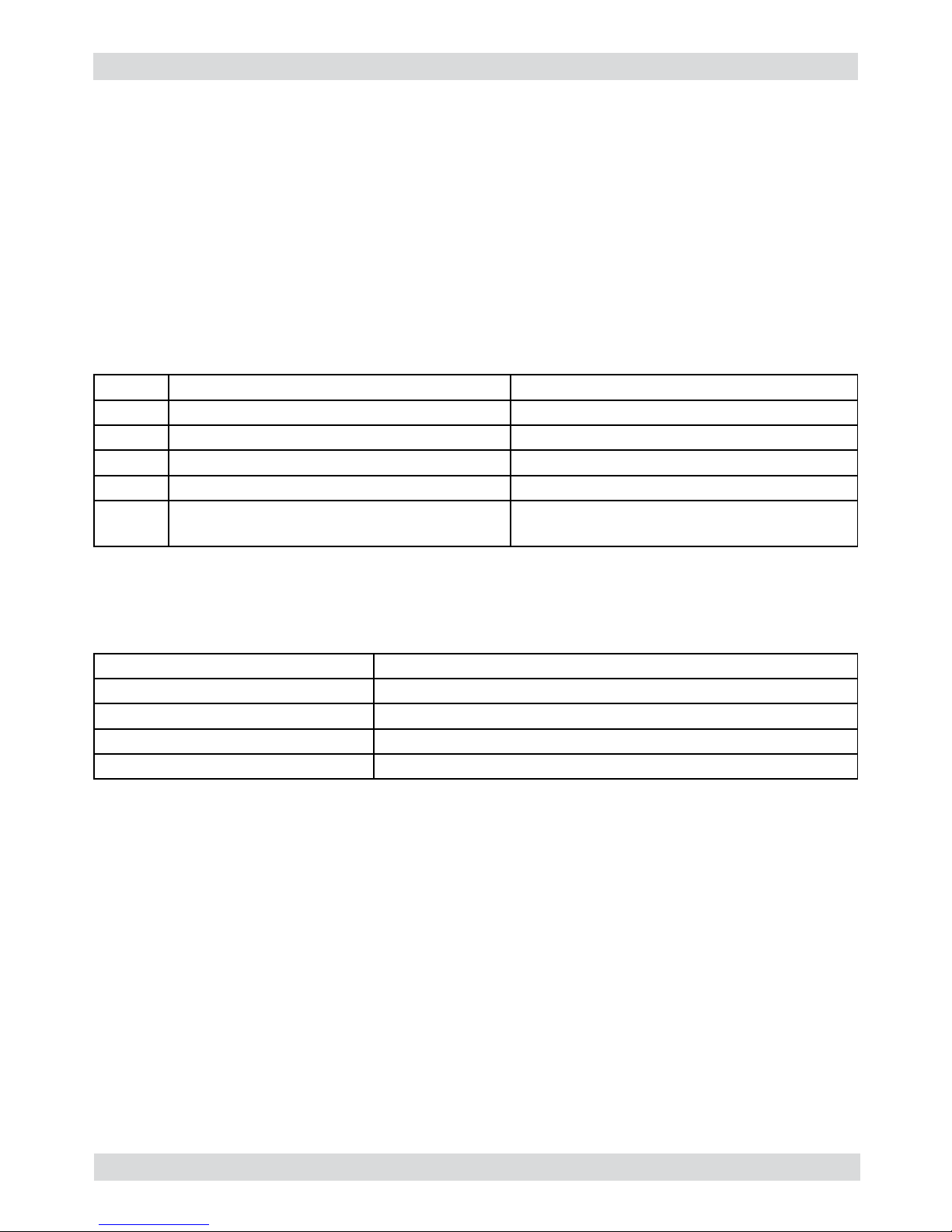
1.2 Tools and equipment required
As well as the standard equipment, the following is required:
Qty. Description Notes
1 Screwdriver Torx T 8 - T 10 - T 20
1 Pliers for Oetiker clamps
1 CC -A - Vdc tester
1 Digital thermometer Scale limit > 150°C
1 SSC (Saeco Service Center) Programmer
(for programming and diagnostics mode)
1.3 Material
Description Notes
Thermal paste Heating element > 200°C
Descaler Saeco descaler
Grease solvent Personal choice
Silicone grease Safe to use with food
1.4 Safety warnings
We recommend you consult the technical manual of the machine before performing any maintenance work.
Observe all applicable standards relating to the repair of electrical appliances.
Always disconnect the power plug from the mains before beginning repair work.
Simply turning off the main machine power switch is not an adequate safety precaution.
This domestic appliance is rated as insulation class I.
On completion of the repair work, insulation and dielectric rigidity tests must be performed.
01
Page 5
INTELIA 01 INTRODUCTION
Saeco International Group Rev. 03 Page / 05
02
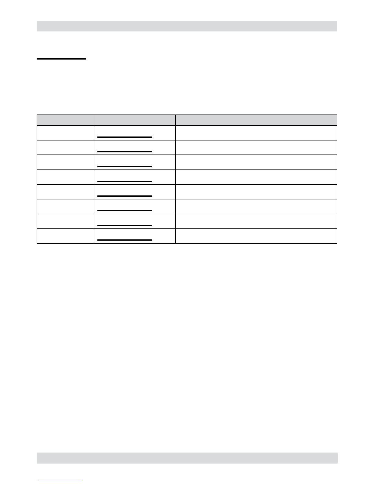
1.5 Service POLICY grid as used for coffee machine
Components Assembly use Single components available
COFFEE
GRINDER
Only for OOW repairs
YES, to consult the specifi c exploded-view of the machine or of the
Coffee Grinder on website
BREWING UNIT Only for OOW repairs
YES, to consult the specifi c exploded-view of the machine or of the
Brewing unit on website
BOILER Only for OOW repairs
YES, to consult the specifi c exploded-view of the machine on web-
site
GEAR
MOTOR
Only for OOW repairs
YES, to consult the specifi c exploded-view of the machine on web-
site
FILTER
HOLDER
Only for OOW repairs
YES, to consult the specifi c exploded-view of the machine on web-
site
MILK
CARAFE
Only for OOW repairs
YES, to consult the specifi c exploded-view of the machine on web-
site
THERMAL
CARAFE
Only for OOW repairs
YES, to consult the specifi c exploded-view of the Thermal Carafe on
website
MILK ISLAND Only for OOW repairs
YES, to consult the specifi c exploded-view of the Milk Island on
website
List of principal assembly present in all our coffee machines
For IN WARRANTY repairs is mandatory to use the single components (not the assembly) available in the exploded views of the
coffee machines or of the specifi c components. If you fi nd the information “SEE THE EXPLODED VIEW E........” in the assembly
description fi eld, it means that the single components of the assembly are available in the other pages of the exploded view. It’s
possible to use the assembly only if there is a specifi c Symptom Cure that include this possibility or when the single components
are not available for the order.
Page 6
INTELIA 01 INTRODUCTION
Saeco International Group Rev. 03 Page / 05
03
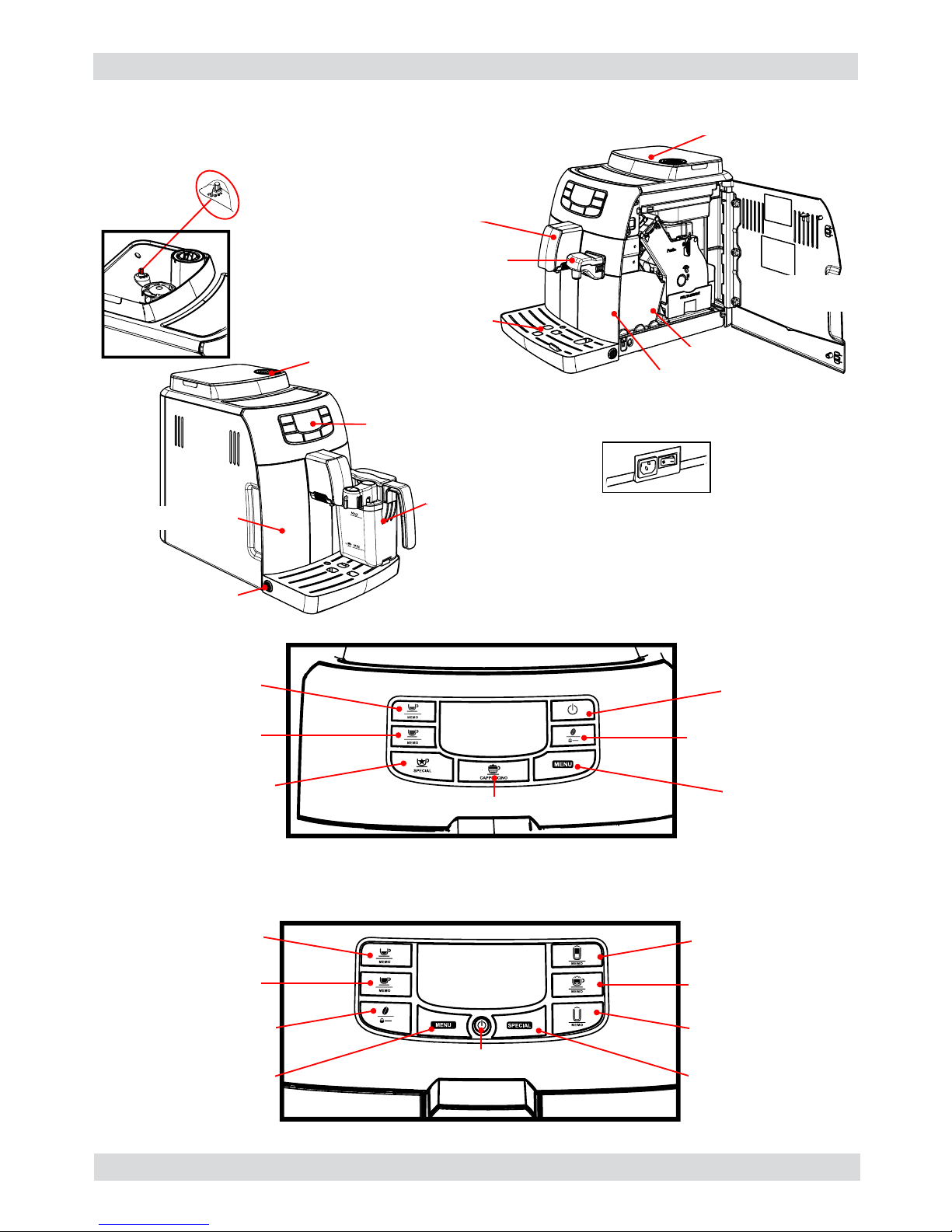
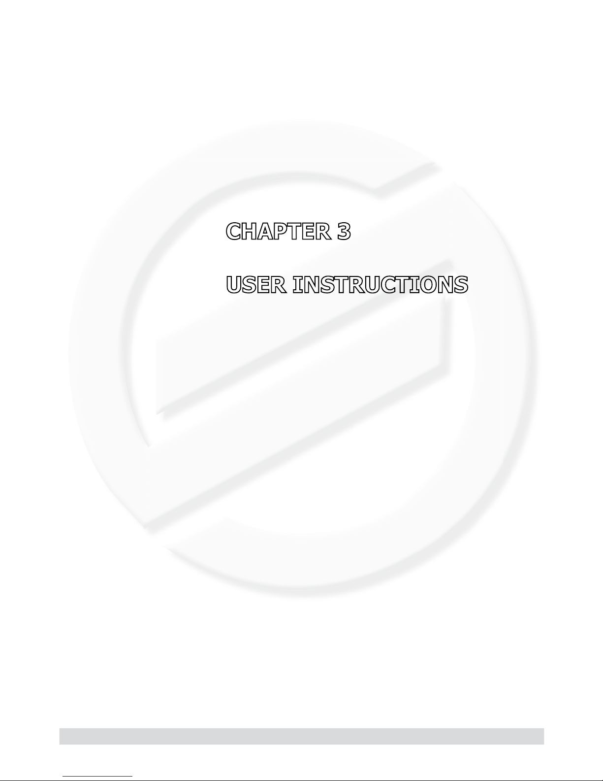
1.6.1 External machine parts
Intelia Cappuccino
Intelia Latte
Grinding
adjustment
Control
panel
Milk carafe
Pre-ground coffee
compartment
Water tank
Drip tray release
button
Display
Espresso coffee brew
button
Latte Macchiato brew
button
Long espresso brew
button
Cappuccino brew
button
“MENU” button
Special beverages
selection button
SON/OFF button
“Aroma” - Pre-ground
coffee button
Hot Milk brew button
Display
cappuccino button
ON/OFF button
Espresso dispensing
button
Long espresso
dispensing button
Hot water/steam
selection button
MENU
button
Aroma / Pre-ground
button
Power cable socket and
main switch
Coffee bean hopper
with lid
Dreg drawer
Water dispenser
(removable)
Coffee dispenser
Brewing unit
Drip
tray+grille
Service
hatch
Page 7
INTELIA 01 INTRODUCTION
Saeco International Group Rev. 03 Page / 05
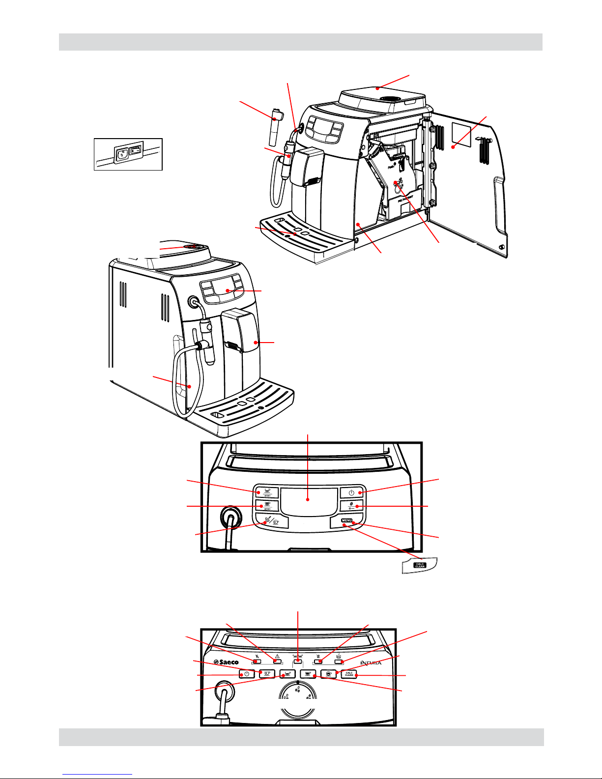
04
Coffee bean
hopper with lid
Hot water/steam
dispensing pipe
Pannarello
(Intelia Focus)
Cappuccino valve
(Intelia Class)
Dreg drawer
Service hatch
Brewing unit
Drip
tray+grille
Intuita
“Coffee grounds
drawer” light
“No water” light
ON/OFF button
Hot water dispensing button
Descaling button
Cappuccino brewing / Steam
dispensing button
Long espresso brew button
“Aroma” selector switch
Espresso coffee brew button
“No coffee” light
“Double coffee” light
“Warning” light
Display
ON/OFF button
Espresso dispensing
button
Long espresso
dispensing button
Hot water/steam
selection button
MENU button
Descaling button
Intelia Focus
Aroma / Pre-ground
button
Intelia Class e Focus
Power cable socket and
main switch
Control
panel
Coffee
dispenser
Water tank
Pre-ground coffee
compartment
Page 8
INTELIA 01 INTRODUCTION
Saeco International Group Rev. 03 Page / 05
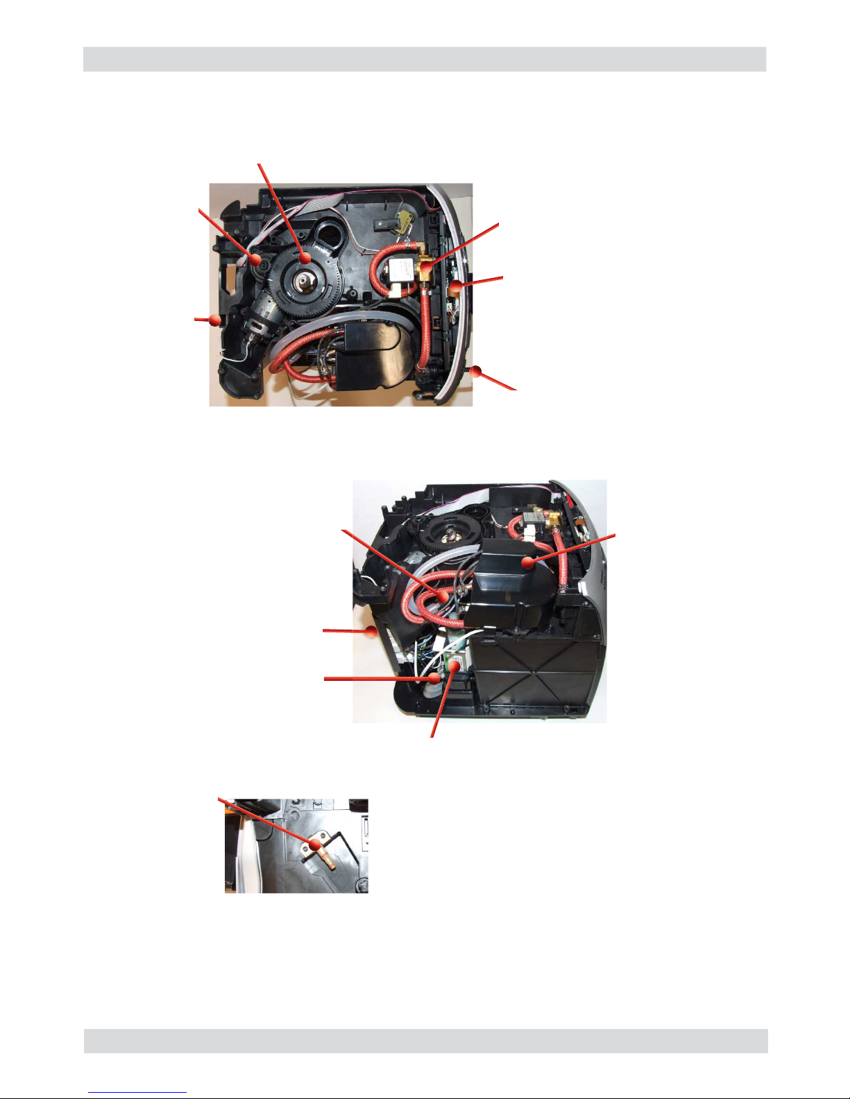
1.6.2 Internal machine parts
05
Boiler pin
Pump
Flow-meter
Power cable connector
Safety valve
Boiler cover and
boiler
Power board
Grinding
adjustment insert
Steam pipe
KYB Interface card
2-way solenoid valve
Coffee grinder
Page 9
Saeco International Group Rev. 03 INTELIA
Page 10
INTELIA 02 TECHNICAL SPECIFICATIONS
Saeco International Group Rev. 03 Page / 04
2.1. Technical specifi cations
Power supply and output: 240 V~ 50 Hz 1850 W - 230 V~ 50/60 Hz 1850 W
Temperature monitoring: (NTC) variable resistor sensor - transmits the value to the
electronic card
Safety system:
2 thermostats at 190°C one shot
Coffee heat exchanger output:
Stainless steel
(230 V~) 1900 W
for coffee, hot water and steam dispensing
Steam heat exchanger output:
Stainless steel
As above
Gear motor: 2 rotation directions; power supply 24VC
Pump: Ulka Type EP5/S GW approx. 13-15 bar with reciprocating
piston and thermal switch 100°C 48 W, 230V, 50 Hz, 120V,
60Hz 100V, 50/60 Hz
Overpressure valve: Opening at approx. 16-18 bar
Water fi lter: In tank
Coffee grinder: Direct current motor with fl at ceramic grinder blades
Automatic dosage: Dose adjustment controlled by the electronic system
Power consumption: During heating phase- approx. 5.6 A
Dimensions: W x H x D in mm: 256x340x440
Weight: 9 kg
Water tank capacity: 1.5 l
Coffee bean hopper capacity: 300 g. of coffee beans
Dreg drawer capacity: 10
Heat exchanger capacity: 10 (11 if after 9 dregs you dispense a double espresso)
Water circuit fi lling time: Approx. 15 sec Max. on fi rst fi lling cycle
Heating time: Approx. 45 sec.
Grinding time: Approx. 8-10 sec.
01
Page 11
INTELIA 02 TECHNICAL SPECIFICATIONS
Saeco International Group Rev. 03 Page / 04
02
2.2. Specifi cation for the measurement of the coffee products temperature.
The temperature is infl uenced by the fl ow from the dispenser and stratifi cation of temperatures in
the glass. In order to consider these phenomena and to introduce measures that allow comparisons in controlled conditions, below guidelines must be followed:
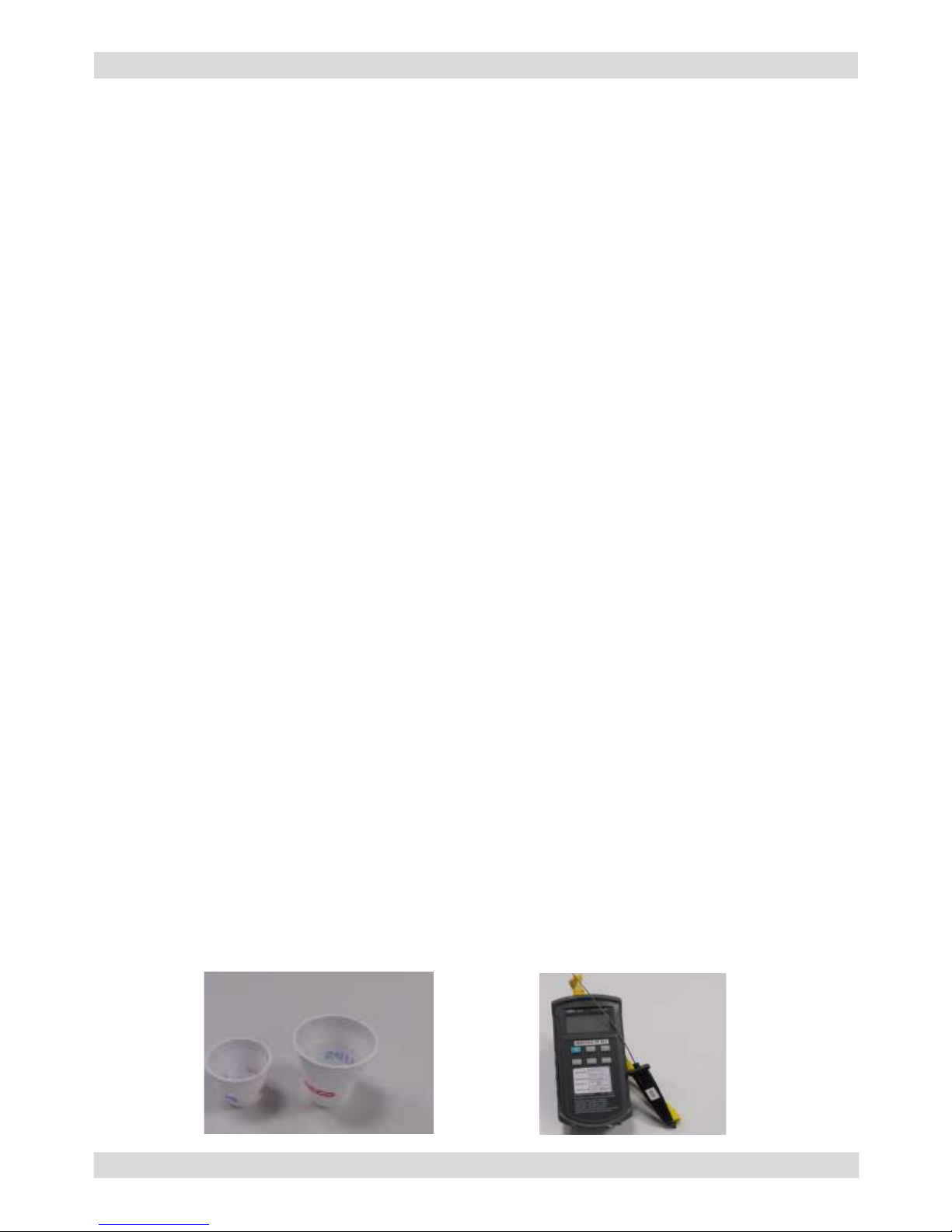
Conditions:
a) Water temperature in tank: 23°C (+/-2°C).
b) It must be used a plastic cup (see picture N°1).
c) It must be used a thermocouple thermometer (e.g. type K - see picture N°2).
d) The coffee machine is tested without any change of parameters or calibrations, which may
affect the temperature of products, so the measurement of temperature must be done with
machine in default factory setting.
Procedure:
1. The temperature must be measured in the cup, immediately after dispensing. Cup has to be
placed on a non-metal surface using a thermocouple thermometer.
2. The temperature in the cup is measured by immersing the probe of the thermometer up to
touch the bottom.The probe then must be moved in a circular motion for 5/6 rotations. At the
of the rotations, stop in the center of the cup.
3. The highest temperature measured during the rotations is the value we are searching for, and
that must be reported;
4. Test measurement: from end of dispensing to the end of rotations must be completed within 12
seconds.
Limits of acceptability
The acceptance limits are divided by features and products and are the following:
Espresso Coffee Italy Q.ty 25/40 gr.
Temperature of 1st product 69°C ≤ 85°C
Temperature of 2nd product 72°C ≤ 85°C
Coffee Q.ty 70/120 gr.
Temperature of 1st product 69°C ≤ 85°C
Temperature of 2nd product 72°C ≤ 85°C
Picture 1
Picture 2
Page 12
INTELIA 02 TECHNICAL SPECIFICATIONS
Saeco International Group Rev. 03 Page / 04
2.3. Machine parameters and performance
PRODUCT
QUANTITY
Minimum
quantity
(Puls.)
Default
quantity
(Puls.)
Maximum
quantity
(Puls.)
User
programmable
Programm. by
Production /
Service
Espresso 50 165 600 Yes No
Long coffee 70 440 600 Yes No
Pre-ground No
Hot water Continues until the water supply has been exhausted (capacitive sensor)
Steam
pannarello
(frother)
Continues until the water supply has been exhausted (capacitive sensor)
RINSE Initial rinse Final rinse
When performed When the machine is switched
on and the boiler temperature is
≤ 50°C
When the machine is switched off
electronically, manually or auto-
matically after 30', if at least one
coffee has been dispensed, be-
fore switching off
No. of pulses 180 80
Stopping option Yes, by pressing any key Yes, by pressing any key
User disable option No No
Production/Service de-
partment disable option
No No
No. of pulses user adjust-
ment option
No No
No. of pulses Production/
Service department ad-
justment option
No No
Pulse range
(Min. – Max.)
No No
03
Descaling cycle frequency
Hard-
ness
Water hardness Without water fi lter With water fi lter
1 Soft (up to 7°dH) 240 litres (480,000 pulses) 480 litres (960,000 pulses)
2 Medium (7° - 14°dH) 120 litres (240,000 pulses) 240 litres (480,000 pulses)
3 Hard (15° - 21°dH) 60 litres (120,000 pulses) 120 litres (240,000 pulses)
4 Very hard (over 21°dH) 30 litres (60,000 pulses) 60 litres (120,000 pulses)
The default water hardness level is 4. Each litre of water corresponds to approximately
2,000 pulses.
Page 13
INTELIA 02 TECHNICAL SPECIFICATIONS
Saeco International Group Rev. 03 Page / 04
WATER TANK Description
Water reserve (pulses) with water fi lter 200
Water reserve (pulses) with no water fi lter 200
Water reserve modifi able by Production/Service
departments
No
"Fill tank" alarm Yes
"No tray" alarm Yes (Fill tank)
Water mains No
DREG DRAWER Description and values
Time-out for dreg drawer
5 sec.
Reset dreg counter
Dreg emptying alarm, if the dreg drawer is
removed for more than 5 seconds.
STANDBY Description and values
Inlet time (default) 30 minutes
Inlet time programmed by Production/Serv-
ice
Yes
Boiler temperature during Standby Boiler OFF
04
Page 14
Saeco International Group Rev. 03 INTELIA
Page 15
INTELIA 03 USER INSTRUCTIONS
Saeco International Group Rev. 03 Page / 10
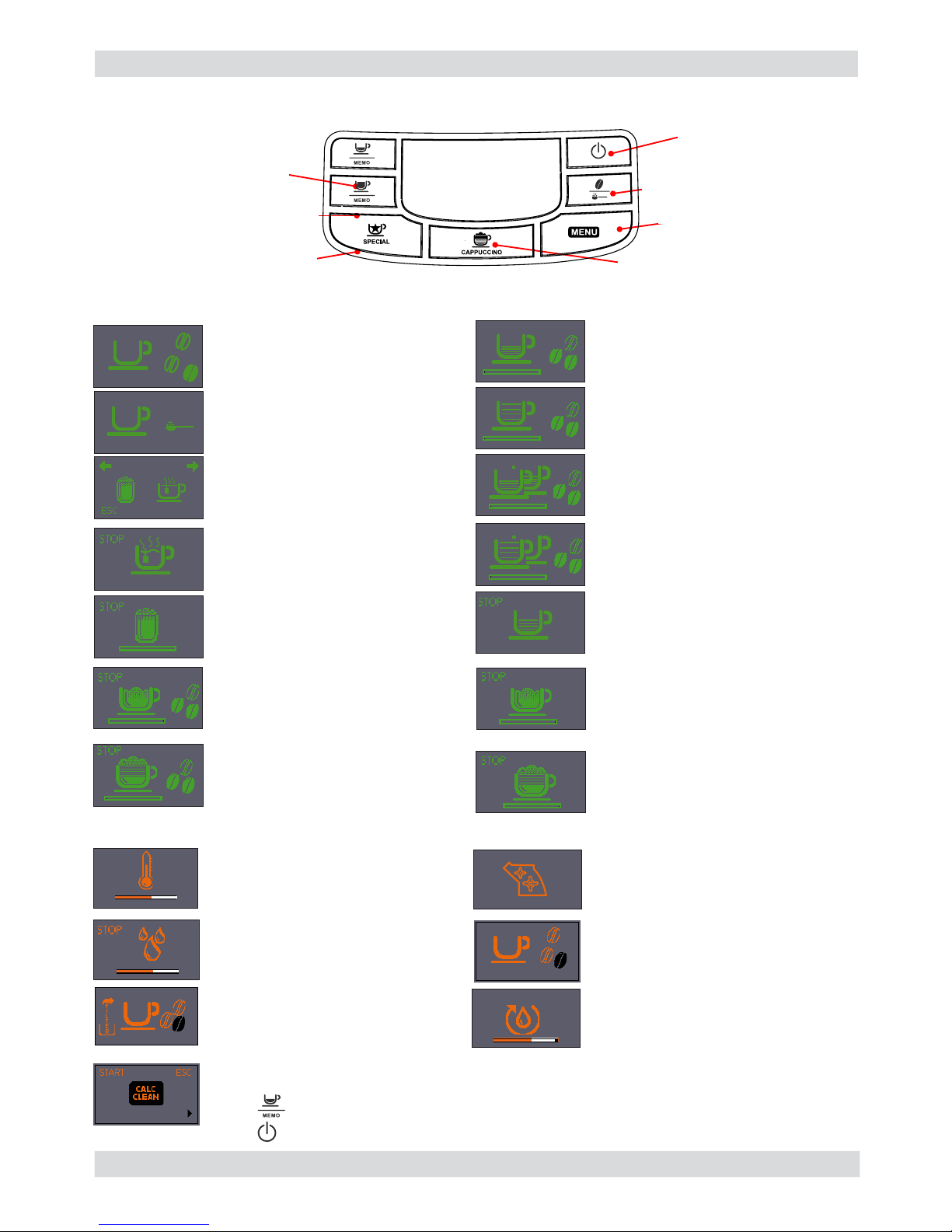
3.1. Intelia Cappuccino customer and programming menu
01
If this screen appears after you switch the machine on, it means that you must run
a descaling cycle.
Press “
” to access the descaling menu and consult the relative paragraph.
Press “ ” to continue using the machine.
Notice signals (
ORANGE)
Machine at correct temperature
- for coffee bean dispensing
- for hot water dispensing
Machine at correct temperature
- for ground bean dispensing
(pre-ground)
Hot water or hot milk selection
Hot water dispensing
Dispensing hot milk
Machine dispensing
1 espresso
Machine dispensing
2 espresso
Machine dispensing
1 coffee
Machine dispensing
2 coffees
The machine is being programmed
with the coffee cup fi ll level
Machine in pre-heating phase
for coffee, hot water and steam
dispensing
The appliance is rinsing, wait
until end of operation
The machine signals that the
“INTENZA+” fi lter must be
replaced
Brewing unit resetting during
appliance reset
Fill the coffee bean container and
start the dispensing cycle
Proceed to load the circuit
ON/OFF button
espresso dispensing
button
Long espresso
dispensing button
special beverages
selection button
cappuccino dispensing button
button MENU
Aroma button / Pre-ground
button
Machine dispensing milk during
the preparation of cappuccino
Machine dispensing coffee during
the preparation of cappuccino
The machine is being programmed
with the amount of milk to be
dispensed to prepare cappuccino
The machine is being programmed
with the amount of coffee to be
dispensed to prepare cappuccino
MEMO
MEMO
MEMO
Machine ready signals (GREEN)
Page 16
INTELIA 03 USER INSTRUCTIONS
Saeco International Group Rev. 03 Page / 10
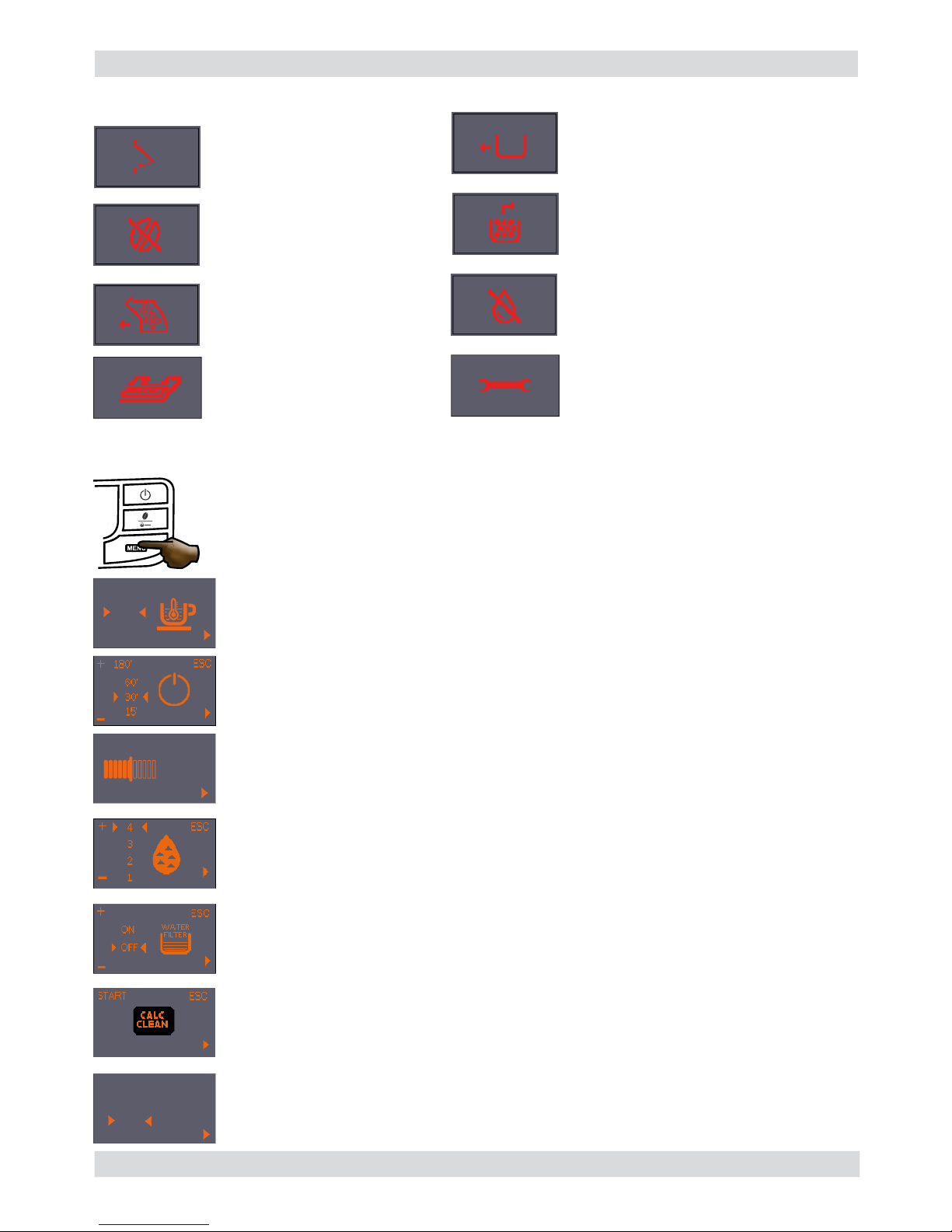
02
Alarm signals (RED)
MENU (commands and programming)
Close the service door.
No beans inside the coffee
container.
After fi lling the container, the
cycle can be restarted.
The Brewing Unit must be
inserted in the machine.
Insert the dreg drawer.
Empty the dreg drawer and the drip
tray.
Fill water tank.
Insert the drip tray as far as it
will go.
You can access the programming menu only when the machine is on.
Press the menu button to access programming.
Coffee temperature:
This function allows the coffee dispensing temperature to be adjusted.
Timer (stand-by)
This function lets you adjust the time for switching to Stand By after the last
dispensing.
Contrast
This function lets you adjust the display contrast for better viewing of the
messages.
“INTENZA+” water fi lter
This function lets you manage the “INTENZA+” water fi lter.
For details see the paragraph concerning the fi lter management.
Descaling Cycle
This function lets you execute a descaling cycle.
Factory settings
This function allows the factory values to be reset.
Water hardness
This function lets you adjust the water hardness so that machine maintenance is
managed better:
1 = very soft water 2= soft water 3 = hard water 4 = very hard water
Switch the machine off, wait for
30 seconds and switch it back on
again. Repeat 2 or 3 times.
If the machine does NOT start, contact
the service center.
ESC
-
+
Display
contrast
ESC
-
+
MAX
MED
MIN
ESC
-
+
YES
NO
DEFAULT
SETTINGS
Page 17
INTELIA 03 USER INSTRUCTIONS
Saeco International Group Rev. 03 Page / 10
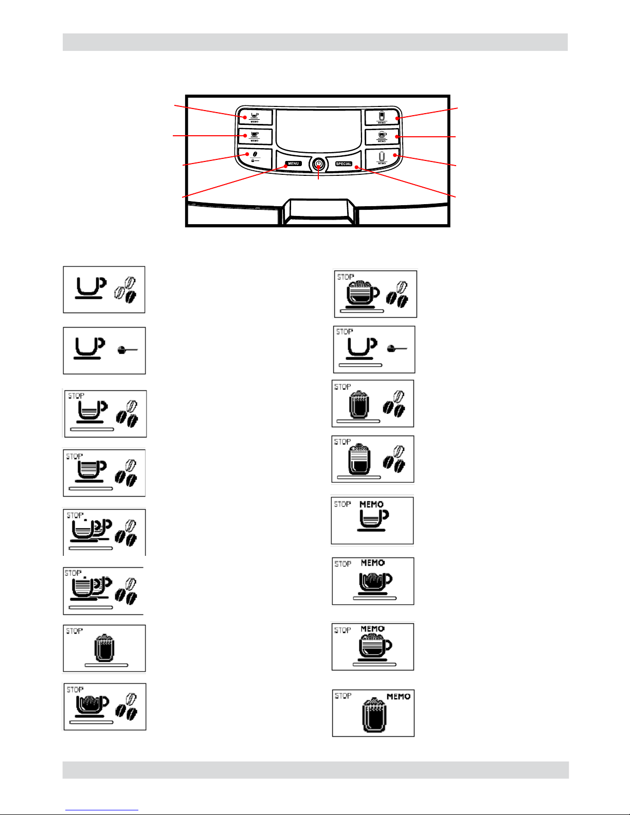
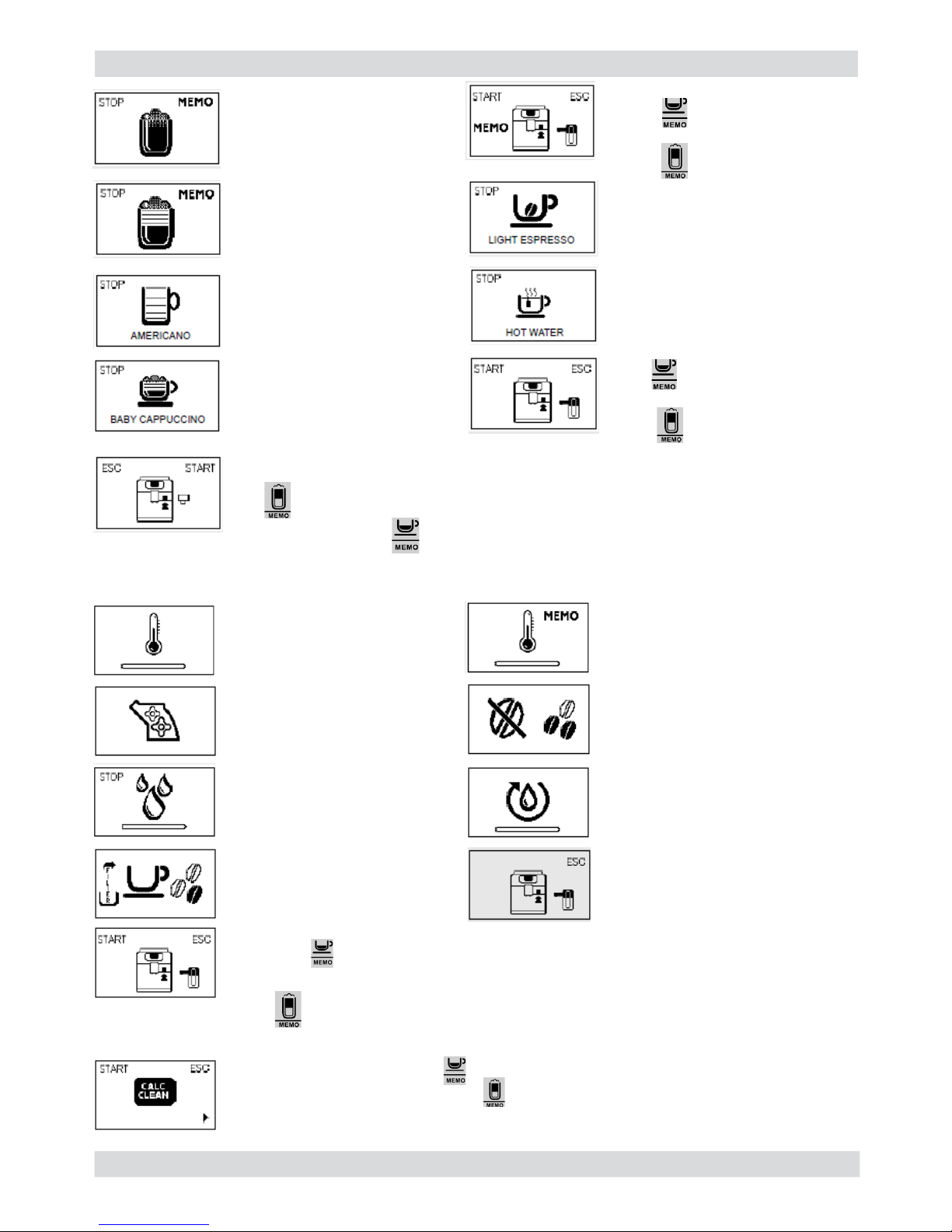
3.2. Intelia Latte customer and programming menu
Ready signals (Green Colour)
Display
Espresso coffee brew
button
Latte Macchiato brew
button
Long espresso brew
button
Cappuccino brew
button
“MENU” button
Special beverages
selection button
SON/OFF button
“Aroma” - Pre-ground
coffee button
Hot Milk brew button
The machine is ready to brew
coff ee from coff ee beans and
to dispense
The machine is ready for brewing
coff ee by using preground
coffee.
The machine is brewing 1 cup
of espresso coffee.
The machine is brewing 1 cup
of long espresso.
The machine is brewing 2
cups of espresso coffee.
The machine is brewing 2
cups of long espresso.
Hot milk brewing.
Milk dispensing phase during
cappuccino preparation.
Coffee brewing phase during
cappuccino preparation.
The machine is brewing 1
cup of espresso coffee by
using ground coffee.
Milk dispensing phase during
the preparation of the Latte
Macchiato.
Coffee brewing phase during
the preparation of the Latte
Macchiato.
The machine is programming
the amount of milk to be
dispensed in order to prepare
a cappuccino.
The machine is programming
the amount of coffee to be
brewed in order to prepare a
cappuccino.
The machine is programming
the amount of milk to be
dispensed in order to prepare
a hot milk.
The machine is programming
the amount of coffee to be
brewed.
03
Page 18
INTELIA 03 USER INSTRUCTIONS
Saeco International Group Rev. 03 Page / 10
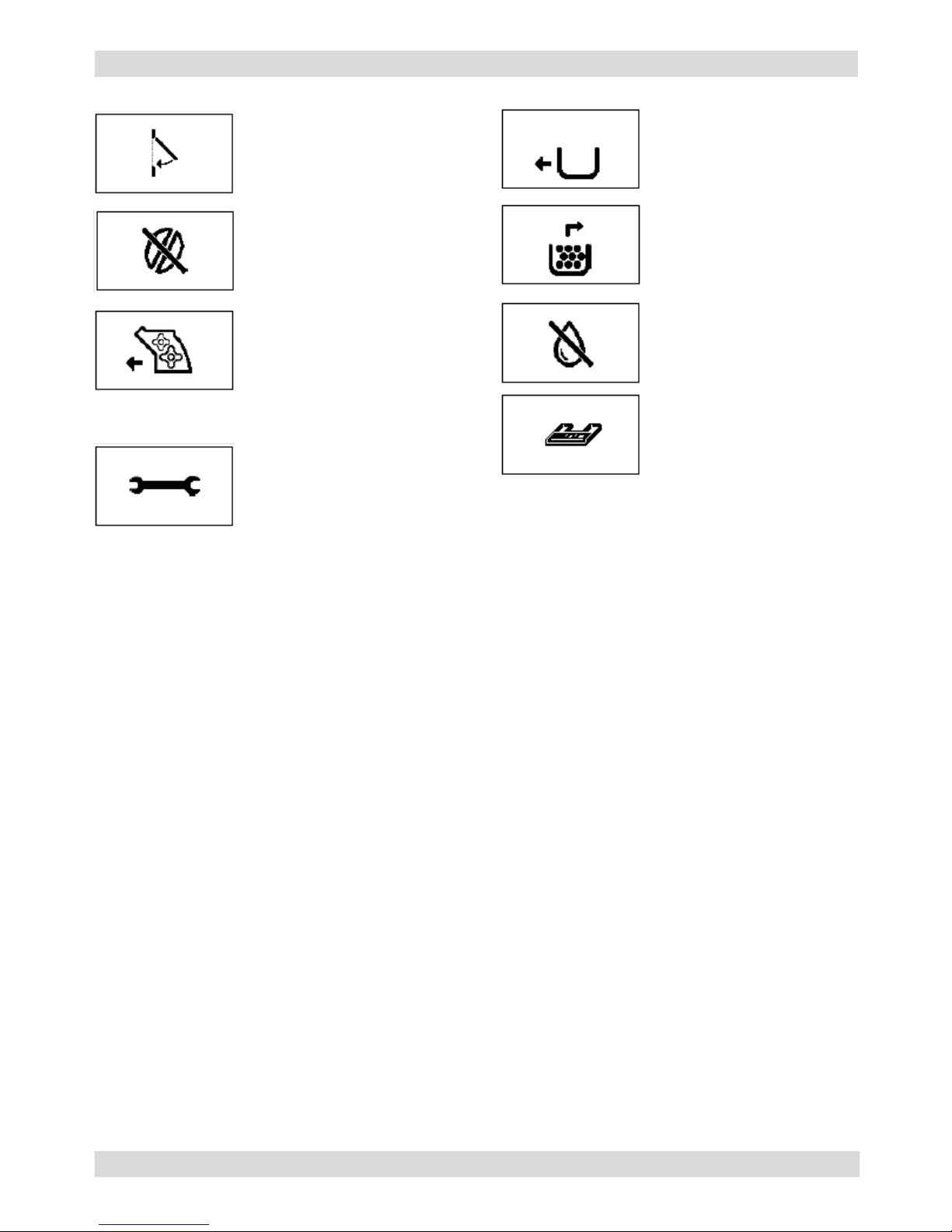
Warning signals (Yellow Colour)
The machine is programming
the amount of milk to be
dispensed in order to prepare
a Latte Macchiato.
The machine is programming
the amount of coffee to be
brewed in order to prepare a
Latte Macchiato.
Brewing of a cup of
“AMERICANO”.
The machine is warming up
to brew coffee and other
products and to dispense hot
water.
The machine is warming up to
brew a product that is currently
being programmed.
The machine reminds you to
insert the carafe before going on
with the descaling cycle.
Prime the circuit.
The Brew Group is being
reset due to machine reset.
The machine is performing
the rinse cycle.
Wait until the machine stops
the operation.
The machine needs the
“INTENZA+”
fi lter to be replaced.
Brewing of a cup of
“BABY CAPPUCCINO”.
Brewing of a cup of
“LIGHT ESPRESSO”.
Hot water dispensing.
Insert the water dispensing
spout and press the
“ “button to start the
dispensing. Press “ “ to
exit.
Press” “ to exit.
If this page is displayed after starting the machine, this means that the descaling
cycle is needed. Press the “ “ button to enter the descaling menu and refer to
the relevant section. Press the “ “ button to go on using the machine. Please
bear in mind that failure to descale your machine will prevent it from working
properly. Repair is not covered by warranty.
Insert the milk carafe and
press the “ “ button to
clean the carafe.
Insert the milk carafe and press
the “ “ button to start the
brewing and save.
Press “ “ to exit.
Insert the milk carafe and press
the “ “ button to start the
brewing.
Press” “ to exit.
04
Page 19
INTELIA 03 USER INSTRUCTIONS
Saeco International Group Rev. 03 Page / 10
05
Warning signals (Read Colour)
Close the service door
No coffee beans in the coffee
bean hopper. After refi lling
the hopper, the cycle can be
restarted.
Insert the coffee grounds
drawer.
Empty the coffee grounds
drawer and the liquid
recovery tray.
Insert the drip tray until it
locks into place.
Fill the water tank.
The Brew Group must be
inserted into the machine.
Turn off the machine. After 30
seconds, turn it on again. Try
this 2 or 3 times.
If the machine does not start,
contact the consumer care
help line at the phone number
listed on the last page of
this document.
Page 20
INTELIA 03 USER INSTRUCTIONS
Saeco International Group Rev. 03 Page / 10
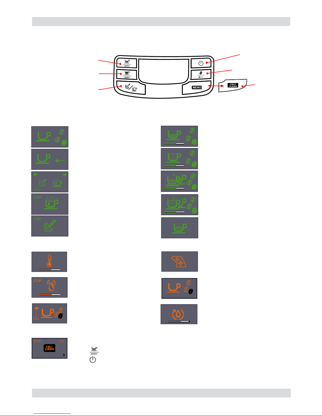
3.3. Intelia Focus and Class customer and programming menu
MEMO
06
ON/OFF button
espresso dispensing
button
Long espresso
dispensing button
Hot water/steam
selection button
Descaling button
(Focus)
Aroma / Pre-ground button
If this screen appears after you switch the machine on, it means that you must
execute a descaling cycle.
Press “
” to access the descaling menu and consult the relative paragraph.
Press “
” to continue using the machine.
Notice signals (ORANGE)
Machine at correct temperature
- for coffee bean dispensing
- for hot water dispensing
Machine at correct temperature
- for pre-ground coffee dispensing
Hot water /steam selection
Water dispense pipe (spout)
Steam/water dispensing
Machine in phase for dispensing
1 cup of espresso
Machine in phase for dispensing
2 cups of espresso
Machine in phase for dispensing
1 cup of espresso
Machine in phase for dispensing
2 cups of espresso
The machine is being programmed
with the coffee cup fi ll level
Machine in pre-heating phase
for coffee, hot water and steam
dispensing
The appliance is rinsing - wait
until end of operation
The machine signals that the
“INTENZA+” fi lter must be
replaced
Brewing unit resetting during
appliance reset
Fill the coffee bean container and
start the dispensing cycle
Proceed to load the circuit
Machine ready signals (
GREEN)
Page 21

INTELIA 03 USER INSTRUCTIONS
Saeco International Group Rev. 03 Page / 10
07
ESC
-
+
Display
contrast
ESC
-
+
MAX
MED
MIN
ESC
-
+
YES
NO
DEFAULT
SETTINGS
Alarm signals (
RED)
MENU (commands and programming)
Close the service door.
No beans inside the coffee
container.
After fi lling the container, the
cycle can be restarted.
The Brewing Unit must be
inserted in the machine.
Insert the dreg drawer.
Empty the dreg drawer and the
drip tray.
Fill water tank.
Switch the machine off, wait for 30 seconds. Repeat 2 or 3 times.
If the machine does NOT start, remove brewing unit, clean it, grease it and re-insert.
If the problem persist contact the service center.
The programming menu can be accessed only when the machine is switched on
Press the menu button to access the programming menu
Coffee temperature (only Class)
This function allows the coffee dispensing temperature to be adjusted.
Timer (stand-by) (only Class)
This function lets you adjust the time for switching to Stand By after the last
dispensing.
Contrast (only Class)
This function lets you adjust the display contrast for better viewing of the
messages.
“INTENZA+” water fi lter (Focus and Class)
This function lets you manage the “INTENZA+” water fi lter.
For details see the paragraph concerning the fi lter management.
Descaling Cycle (Focus and Class)
This function lets you execute a descaling cycle.
Factory settings (only Class)
This function allows the factory values to be reset.
Water hardness (Focus and Class)
This function lets you adjust the water hardness so that machine maintenance is
managed better:
1 = very soft water 2= soft water 3 = hard water 4 = very hard water
Page 22
INTELIA 03 USER INSTRUCTIONS
Saeco International Group Rev. 03 Page / 10
08
“Coffee grounds
drawer” light
“No water” light
ON/OFF button
Hot water dispensing button
Descaling button
Cappuccino brewing / Steam
dispensing button
Long espresso brew button
“Aroma” selector switch
Espresso coffee brew button
“No coffee” light
“Double coffee” light
“Warning” light
3.4. Intuita customer and programming menu
BLINKING
Machine in Stand-by.
BLINKING
The machine is performing
the rinse cycle.
BLINKING
The machine is in the
warm-up phase.
STEADY ON
The machine is ready
for use.
STEADY ON
Hot water is being
dispensed.
STEADY ON
The machine is brewing 2
cups of espresso coffee.
STEADY ON
The machine is brewing 1
cup of coffee.
STEADY ON
The machine is brewing 2
cups of coffee.
BLINKING
The machine is reprogramming
the amount of coffee necessary to
brew a cup of espresso coffee.
BLINKING
The machine is reprogramming
the amount of coffee necessary to
brew a cup of coffee.
STEADY ON
Steam is being dispensed.
STEADY ON
The machine is brewing
1 cup of espresso coffee.
STEADY ON
The machine needs a descaling cycle.
Please bear in mind that failure to descale your machine will prevent it from working
properly. Repair is not covered by warranty.
Page 23
INTELIA 03 USER INSTRUCTIONS
Saeco International Group Rev. 03 Page / 10
BLINKING
Prime the circuit.
BLINKING
Insert the coff ee grounds
drawer.
BLINKING
Close the service door. The Brew
Group must be inserted into the
machine.
FAST BLINKING
Empty the coffee grounds
drawer and the liquid recovery
tray.
STEADY ON
No coff ee beans in the coffee bean
hopper. After refi lling the hopper,
the cycle can be restarted.
STEADY ON
Fill the water tank.
BLINKING
Turn off the coffee machine. After 30 seconds, turn it on again. Try this 2 or 3 times.
If the machine does not start, contact the consumer care help line at the phone
number listed on the last page of this document.
Alarm signals
09
Page 24
INTELIA 03 USER INSTRUCTIONS
Saeco International Group Rev. 03 Page / 10
CLEANING AND TECHNICAL SERVICING
A Empty the dregs drawer When indicated
B Empty the drip tray As necessary
C Clean the water tank Weekly
D Clean the coffee bean hopper As necessary
E Clean the casing As necessary
F
Clean the brewing unit Every time the coffee bean hopper is fi lled or weekly
Lubricate the brewing unit After 500 dispensing cycles or when the grease is no
longer present on the brewing unit
Clean the unit housing Weekly
H Descaling When indicated
Descaling cycle frequency
Hardness Water hardness Without water fi lter With water fi lter
1 Soft (up to 7°dH) 240 litres (480,000 pulses) 480 litres (960,000 pulses)
2 Medium (7° - 14°dH) 120 litres (240,000 pulses) 240 litres (480,000 pulses)
3 Hard (15° - 21°dH) 60 litres (120,000 pulses) 120 litres (240,000 pulses)
4 Very hard
(over 21°dH)
30 litres (60,000 pulses) 60 litres (120,000 pulses)
The default water hardness level is 3. Each litre of water corresponds to approximately 2,000 pulses
3.5. Operation, cleaning and maintenance
Operating the machine
1 Fill water tank
2 Fill the coffee bean hopper
3 Switch on the appliance
4
Press the button to start the
appliance
5 Heating When the heating phase begins, wait for it to fi nish
6 Rinse Carry out a rinse cycle for the internal circuits
7 Machine ready The machine is ready to dispense beverages
10
Page 25

Saeco International Group Rev. 03 INTELIA
Page 26

INTELIA 04 OPERATING LOGIC
Saeco International Group Rev. 03 Page / 08
4.1. Water circuit
01
Milk carafe
Compensation valve water outlet
Flow-meter
1900 W boiler
Water
Hot water /steam
Compensation valve water outlet
Pump
Water tank
• Traditional water system
• Flow meter – Amount of coffee dispensed
into the cup
• Reciprocating piston type pump
(13 - 15 bar)
• Compensation valve
(opening pressure 16 - 18 bar)
• Boiler – 1900 W
• Two-way solenoid valve
Three-way solenoid valve
Intelia Cappuccino
Brewing unit
Three-way
solenoid valve
Page 27

INTELIA 04 OPERATING LOGIC
Saeco International Group Rev. 03 Page / 08
Steam pipe
Compensation valve water outlet
Flow-meter
1900 W boiler
Water
Hot water /steam
Two-way solenoid valve
Pompa
Water tank
Brewing unit
• Traditional water system
• Flow meter – Amount of coffee dis-
pensed into the cup
• Reciprocating piston type pump
(13 - 15 bar)
• Compensation valve
(opening pressure 16 - 18 bar)
• Boiler – 1900 W
• Two-way solenoid valve
Intelia Focus e Class
02
Page 28

INTELIA 04 OPERATING LOGIC
Saeco International Group Rev. 03 Page / 08
Notes: * Only with Pre-brewing
4.2. Coffee cycle
Switching on
When the machine is switched on, the gear motor repositions itself as follows:
- It acts on microswitch 1 (see following chapter).
- The gear motor changes its rotation direction and moves upwards again by approx. 1-2 mm.
- The boiler begins to heat the water for approx. 45 sec., at full power, in order to reach the
optimal temperature. The temperature will then remain at a constant level.
Coffee cycle
1. The coffee grinder starts the grinding process (controlled by pulses generated by a sensor).
2. The gear motor (brewing unit) moves to the brewing position.
3. Preliminary dispensing phase (short pump activity, short pause).
4. Product dispensing (the pump operation period is defi ned by the amount of product dis-
pensed).
5. The gear motor moves to its home position (the dregs are expelled automatically).
Main switch ON START STOP
Time
Coffee grinder
Heating
Pump
Brewing unit gear
motor
Status Heating Ready Coffee cycle
Pulses
(Dosage)
Pump operation (fl ow
meter pulses) in
accordance with the
amount of product
selected.
approx.
45 sec.
*
03
Single microswitch gear motor
Status
Microswitch
OFF
ON
Page 29

INTELIA 04 OPERATING LOGIC
Saeco International Group Rev. 03 Page / 08
An NTC is used as a temperature sensor; in the event of overheating this reduces boiler
element power consumption.
The electronic system detects the current boiler temperature from the drop in voltage of the
sensor and adjusts it accordingly.
Heating element values and corresponding temperatures: see table.
4.4. Temperature sensor (adjustment)
Temp. (°C) R nom (kΩ) ΔR (+/- %)
20 61.465 8.6
50 17.599 5.9
75 7.214 4.1
80 6.121 3.7
85 5.213 3.4
90 4.459 3.1
100 3.3 2.5
125 1.653 3.9
150 0.893 5.1
4.3. Single microswitch
The gear motor is powered by a direct current motor that engages with the smaller
double toothed wheel using a worm screw.
The unit is mounted on the axle of the large
gear wheel and when a coffee is requested, it
moves from the standby position to the dispensing position, and then back to the standby position again.
- Standby position: 1
- Dispensing position: 2
2
1
04
Page 30

INTELIA 04 OPERATING LOGIC
Saeco International Group Rev. 03 Page / 08
4.5. Coffee grinder
2
3
4
5
6
1
4.6. Low bean level detection, dose quantity adjustment, coffee grinder
blocked
Without beans n=100%
With beans n=100%
Without beans n=50%
With beans n=50%
The coffee grinder is driven by a direct current motor (1) using a worm screw helicoidal wheel
transmission (2).
The worm screw (2) drives a plastic gear wheel (3), which turns the lower grinder (4) and the
increment pin (5)
There are two magnets (6) in the gear wheel; at every rotation these induce two pulses to a Hall
sensor, which in turn transmits them to the electronic system.
No coffee
A low coffee bean level is detected by the Hall sensor,
after variations in the pulse frequency (with or without
coffee).
If there are no coffee beans (operation while empty),
the number of rotations – and therefore the number of
pulses – will be greater.
t1 = no coffee indication
If, however, there are coffee beans, the number of
rotations will be lower due to the force created by the
grinding.
t2 = no indication
t3 and t4 = this measurement is performed at the end
of each grinding process
Dose quantity adjustment
The dose quantity is adjusted in accordance with the
pulses detected (number of rotations proportional to the
selected fl avor – mild, medium or strong).
Coffee grinder blockage
If the coffee grinder becomes blocked for any reason,
pulses will no longer be transmitted to the electronic
system and the grinder will come to a stop.
05
Page 31

INTELIA 04 OPERATING LOGIC
Saeco International Group Rev. 03 Page / 08
4.7. Dose self-learning (SAS)
06
The aim of this function is to automatically regulate the average dose of ground coffee (SELFLEARNING); this takes place with an algorithm based on three pieces of data that the machine
receives via the card:
1. Number of coffee grinder pulses during the grinding cycle.
2. Max. average value of the power consumed by the gear motor during the coffee brewing cycle.
3. Aroma selected by the user.
The algorithm compares the maximum average value of the power consumed by the gear motor
with the value listed in the table for the selected aroma, in order to calculate the new grinding
pulse value for the next coffee produced.
If the power consumption value is less than the minimum current value, the grinding pulses will
be increased by 2.
If the power consumption value is greater than the maximum current value, the grinding pulses
will be decreased by 4.
If the power consumption value falls within the “over-torque” interval, the product will be dispensed and the grinding pulses will be decreased by 10.
If the power consumption value falls within the “abort cycle” interval, the dreg will be expelled
and the grinding pulses will be decreased by 10.
If the “pre-ground” fl avour is selected by the user, no modifi cation will be made.
This guarantees that, regardless of the coffee type used, the grinding level setting
and the wear on the grinders, the ground coffee dose always remains constant.
Important:
For perfect operation, machine adjustment should take place in the area of the fi elds
highlighted in green (A, B, C). When the type or brand of coffee is changed, there may be
variations in the size of the beans and their stickiness or roasting level. This leads to variations
in power consumption (mA), with resulting excessive or insuffi cient doses (until the necessary
adjustments have been made to compensate for this change).
Caution: In the case of excessive dosage, powder may be expelled into the dreg
drawer. This is not a fault, but can occur during preliminary operation or after a
service.
Setting/Status
Power consumption
in mA
Pulses corrected in the next grinding process
In the event of absorp-
tion above the range
In the event of absorp-
tion below the range
A Mild aroma 200 - 300 mA - 4 +2
B Medium Aroma 301 - 450 mA - 4 +2
C Strong Aroma 451 - 600 mA - 4 +2
D Over-limit 601 - 800 mA - 4
E Overwork 801 - 1000 mA - 10
F Dreg expulsion > 1000 mA - 10
Page 32

INTELIA 04 OPERATING LOGIC
Saeco International Group Rev. 03 Page / 08
4.8. Water level detection (water tank)
“Water low” message (water reserve)
Function:
The water level is monitored by a capacitative sensor, located one
third of the way up the water tank wall.
If the electronics assembly detects, by means of the sensor,
that the amount of water in the tank has dropped below the
above mentioned level, a water reserve remains available for
the dispensing process underway (this will cover 200 fl ow meter
pulses).
The product dispensing process will then come to an end.
If a dispensing cycle ends after the sensor has been triggered (in
the reserve) then the display “Water low” continues to be displayed
during the following dispensing cycle.
200 puls.
Sensor
Water tank
07
“Descaling” – message with water fi lter
inserted
(appliances with display only)
The water hardness is set on the basis of the
regional water hardness analysis
(1, 2, 3, 4).
Filter off:
If the function is turned o the electronics
assembly monitors the fl ow meter pulses,
recording one pulse each turn.
Filter on:
If the function is turned on the electronics
assembly monitors the fl ow meter pulses,
recording one pulse every two turns.
“Change water fi lter” message
The electronics assembly uses the fl ow meter
impulses to keep track of the amount of water
which has fl owed through; after the specifi ed
amount (set in accordance with the water
hardness level), the “Replace fi lter” message
appears.
4.9. Descaling request
360°
1 rev
Number of pulses
Filter
on
Filter
off
Flow meter pulses
Page 33

INTELIA 04 OPERATING LOGIC
Saeco International Group Rev. 03 Page / 08
Water fi lter
Function:
• Reduced limescale deposits which take longer to
form.
• Improved water quality.
• Improved taste due to the ideal water hardness.
Life span / descaling performance:
• - 10 ° dH
• 60 litres
• 2 months
To achieve the best possible operating mode consistency
over the total life span, the water is channelled using
a 3-stage bypass (A, B, C) depending on the degree of
hardness. See small image.
Bypass
4.10. Water fi lter
08
1) Steam input
2) Cappuccino maker
3) Bring the cappuccino maker into dispensing position before
inserting the carafe in its seat
4) Milk tank
4.11. Intelia Cappuccino milk carafe
The steam passes through the pipe
creating a sucking effect that pulls
the milk upwards
The milk is heated by the steam
and taken towards the emulsion
chamber where it is mixed with air
and transformed into foam
Emulsifi ed milk
Emulsion chamber
Steam
Steam
Emulsifi ed
milk
Carafe
Milk
Milk
1
2
4 3
Page 34

Saeco International Group Rev. 03 INTELIA
Page 35

INTELIA 05 TROUBLESHOOTING
Saeco International Group Rev. 03 Page / 22
5.1.1. Intelia Cappuccino test mode
Entry into Test Mode results in a screen divided into sections, as illustrated in the diagram below.
Firmware Software version
Operational check – keys
Operational check microswitches and sensors
Shows the version of the fi rmware loaded and the internal checksum (it
gives univocal traceability)
Initial status
Initial status.
The letter next to it changes from N to Y when only one button is pressed.
By pressing buttons 1, 3, 4, 6 the display color changes from GREEN to RED.
By pressing buttons 2, 5 and 7 the display color changes from GREEN to
YELLOW.
Button 4 must be pressed at the end only once, since pressing it moves on to
the next page.
ERROR condition:
The letters do not change from N to Y or are always Y, in this case check the fl at communication
cable with the Control Board/Power Board, if it does not change color check the cable JP4 too.
Insert full water tank
The TANK-H20 indicator must change from “N” to “Y”
ERROR Condition:
If the indication does not change, check the capacitive sensor and relative wiring
(JP23).
01
To enter Test Mode
1. Hold down the buttons Espresso
and Menu.
2. Turn on the main switch at the
rear of the machine
1
2
Press STAND_BY “ ” to move to the next screen
Insert the dreg drawer
The DREG indicator must change from “N” to “Y”
ERROR Condition:
If the indication does not change, check the microswitch on the dreg drawer
and relative wiring (JP16).
Press STAND_BY “ ” to move to the next screen
Page 36

INTELIA 05 TROUBLESHOOTING
Saeco International Group Rev. 03 Page / 22
02
Close the side door (the dreg drawer must already be in position)
The DOOR indicator must change from “N” to “Y”
ERROR condition:
If the indication does not change, check the Microswitch on the hatch and
relative wiring (JP14), make sure that the dreg drawer is correctly in position.
Insert the brewing unit
The BU-P indicator must change from “N” to “Y”
ERROR Condition:
If the indication does not change, check the brewing unit microswitch and
relative wiring (JP16).
Insert the dreg drawer
The TRAY indicator must change from “N” to “Y”
ERROR Condition:
If the indication does not change, check the brewing unit microswitch and
relative wiring (JP4).
Insert the Carafe
The CARAFE indicator must change from “N” to “Y”
ERROR Condition:
If the indication does not change, check the brewing unit microswitch and
relative wiring (JP25).
Insert the Water Coupling
The TAP indicator must change from “N” to “Y”
ERROR Condition:
If the indication does not change, check the brewing unit microswitch and
relative wiring (JP25).
Initial status
Operational check - milk inputs
Press STAND_BY “ ” to move to the next screen
The COM indicator must be left on USCP.
Press STAND_BY “ ” to move to the next screen
Operational check – brewing unit
Initial status
Page 37

INTELIA 05 TROUBLESHOOTING
Saeco International Group Rev. 03 Page / 22
03
Press the ESPRESSO button to move the unit to Work position. When
the unit is in position, the WORK indication changes from “N” to “Y”, the
absorption current must be less than 200mA without the brewing unit on,
and less than 300mA with the brewing unit on.
The WORK indicator remains permanently on “N”
ERROR condition:
The WORK indicator changes, and remains permanently on “N”, while the
backlight changes from green to red; check the microswitch, unit motor
(this may be blocked) and lastly the wiring JP16 and JP14.
ERROR condition:
(without brewing unit):
If the absorbed current exceeds 200 mA the display turns red, check the
gears on the motor and the motor housing in its seat.
ERROR condition:
(with brewing unit):
If the absorbed current exceeds 300 mA the display turns red, check the
brewing unit, the gears on the motor and the motor housing in its seat.
Press the COFFEE button to shift the unit into Home position. When the
unit reaches HOME position the indication changes from “N” to “Y”, the
absorption current must be less than 200mA without the unit or less than
300 mA with the unit on.
The HOME indicator remains permanently on “N”
ERROR condition:
The HOME indicator changes, and remains permanently on “N”, while the
display changes from green to red; check the microswitch, unit motor (this
may be blocked) and lastly the wiring JP16 and JP14.
ERROR condition:
(without brewing unit):
If the absorbed current exceeds 200 mA the display turns red, check the
gears on the motor and the motor housing in its seat.
ERROR condition:
(with brewing unit):
If the absorbed current exceeds 300 mA the display turns red, check the
brewing unit, the gears on the motor and the motor housing in its seat.
Press STAND_BY “ ” to move to the next screen
Page 38

INTELIA 05 TROUBLESHOOTING
Saeco International Group Rev. 03 Page / 22
Operational check - coffee grinder and boiler
Initial Status
If the following screen appears it means that the dreg drawer is not
correctly inserted, or that the side door is not completely closed. The
screen will disappear only after the drawer has been inserted or the door
closed.
Press the ESPRESSO button to activate solenoid valve EV1 (2-way, normally
closed).
The solenoid valve is activated and the indication to the right of EV1
changes from “OFF” to “ON”.
Press the COFFEE button to activate solenoid valve EV2 (3-way, normally
open).
The solenoid valve is activated and the indication to the right of EV2
changes from “OFF” to “ON”.
Press the AROMA button to activate solenoid valve EV2 (3-way, normally
open).
The water is dispensed from the steam pipe. IMP indicates an increasing
number of pulses. L/H must be between 10 and 18.
ERROR:
The pulses remain at 0, the display turns red, this means there is an error
in the water circuit. If water is coming out of the coupling,it means there is
an error in the fl ow meter or in its wiring in the Control Board/Power Board
(JP5). If no water is coming out, check the pump, the connected water
circuit, or the pump wiring (JP24).
Initial status
Press Aroma to switch on the grinder
The coffee grinder starts to spin and the number of pulses is indicated by
the number circled in red, the other numbers have no signifi cance for this
test.
04
Press STAND_BY “ ” to move to the next screen
Operational check - solenoid valves and pump
Page 39

INTELIA 05 TROUBLESHOOTING
Saeco International Group Rev. 03 Page / 22
05
ERROR:
If the number remains 0, the display turns red, and the motor is running, the problem lies in the Hall sensors, or their wiring, or in the Control
Board/Power Board input (JP2). If the motor does not run, the problem
may lie in the chain (JP8), the coffee grinder wiring or the actual coffee
grinder.
Temperature control
The circled number expresses the boiler temperature in degrees centigrade.
ERROR:
If the HEATER indicator shows the word “SHORT”, this means that the
NTC temperature sensor is in short circuit and the display turns from
green to red. In this case, check the wiring of the NTC or the Control
Board/Power Board (JP13).
ERROR:
If the HEATER indicator shows the word “OPEN”, this means that the
NTC temperature sensor is disconnected, the display turns from green
to red.
In this case, check the continuity of the NTC wiring and check the connection to the Control Board/Power Board (JP13).
Press the COFFEE button to activate the Boiler
The indicator changes from “OFF” to “ON” and shortly after the temperature indicator should start to increase, and any ammeter at the technician’s disposal on the counter must display an absorption of approximately 8 Ampere with 230 volt.
ERROR:
If the temperature is not absorbed check the boiler resistor, relative wiring
and the connection to the Control Board/Power Board input (JP19), also
check the wiring on the NTC (JP13).
If the temperature goes above 125°C then the display turns yellow and
an alarm message appears on the display.
Above this temperature the boiler is always off, avoiding the risk of dangerously high temperatures.
Page 40

INTELIA 05 TROUBLESHOOTING
Saeco International Group Rev. 03 Page / 22
5.1.2. Intelia Focus and Class Test mode
1
2
06
Entry into Test Mode results in a screen divided into sections, as illustrated in the diagram below.
To enter Test Mode
1. Hold down the Espresso and
Menu buttons.
2. Switch on the main switch at
the back of the machine.
Firmware Software version
Operational check – keys
Operational check microswitches and sensors
Shows the version of the fi rmware loaded for Focus and Class.
Initial status
Initial status.
The letter next to it changes from N to Y only when a button is pressed.
By pressing buttons 1, 3, 4, 6 the display color changes from GREEN to RED.
By pressing buttons 2, 5, the display color changes from GREEN to YELLOW.
Button 4 must be pressed at the end only once as when pressed it moves to
the next page.
ERROR condition:
The letters do not change from N to Y or are always Y, in this case check the fl at communication
cable with the power board -Power JP21, if it does not change color check the cable JP4 between
the board and the display.
If you insert a full drip tray the TANK-H20 indicator must change from “N” to “Y”.
ERROR condition:
If the indication does not change, check the capacitive sensor and relative wiring
(JP23).
Press STAND_BY “ ” to move to the next screen
Press STAND_BY “ ” to move to the next screen
Page 41

INTELIA 05 TROUBLESHOOTING
Saeco International Group Rev. 03 Page / 22
Insert grounds drawer
The DREG indicator must change from “N” to “Y”
ERROR condition:
If the indication does not change, check the microswitch on the dreg drawer
and relative wiring (JP16).
Close the side hatch (the dreg drawer must be inserted)
The DOOR indicator must change from “N” to “Y”
ERROR condition:
If the indication does not change, check the Microswitch on the hatch and
relative wiring (JP14), make sure that the dreg drawer is correctly in position.
Insert the brewing unit
The BU-P indicator must change from “N” to “Y”
(this step takes 2-3 sec)
ERROR condition:
If the indication does not change, check the brewing unit microswitch and
relative wiring (JP16)
07
When the unit is in position, the WORK indication changes from “N” to “Y”,
the absorption current must be less than 200mA without the brewing unit
on, and less than 300mA with the brewing unit on.
ERROR condition:
The WORK indicator always stays on “N”
ERROR:
The WORK indicator changes, and remains permanently on “N”, while the
display changes from green to red; check the microswitch, the motor of the
gear motor (this may be blocked) and the wiring JP16.
ERROR (without brewing unit):
If the absorbed current exceeds 200 mA the display turns red, check the
gears on the gear motor and the motor housing in its seat.
Initial status
IMPORTANT: This check can only be carried out with the dreg drawer in and
the side hatch closed
Press the espresso button to move the brewing unit to the “WORK” position
Operational check – brewing unit
Press STAND_BY “ ” to move to the next screen
ERROR (with brewing unit):
If the absorbed current exceeds 300 mA the display turns red, check the
brewing unit, the gears on the gear motor and the motor housing in its seat.
Page 42

INTELIA 05 TROUBLESHOOTING
Saeco International Group Rev. 03 Page / 22
08
When the unit reaches the HOME position the indicator changes from “N” to
“Y”, the absorbed current, without the brewing unit, must be less than 200,
and with the brewing unit less than 300 mA
ERROR condition:
The HOME indicator always stays on “N”
ERROR:
The HOME indicator changes, and remains permanently on “N”, while the
display changes from green to red; check the microswitch, unit motor (this
may be blocked) and the wiring JP16.
ERROR (without brewing unit):
If the absorbed current exceeds 200 mA the display turns red, check the
gears on the gear motor and the motor housing in its seat.
Initial status
Press the espresso button to activate the solenoid valve
Press the aroma button to activate the pump
Press the espresso button to move the brewing unit to the “HOME” position
Operational check - solenoid valve and pump
ERROR (with brewing unit):
If the absorbed current exceeds 300 mA the display turns red, check the
brewing unit, the gears on the gear motor and the motor housing in its seat.
If the dreg drawer is in position and the side hatch closed, the EV cannot be
done. If it is not in the right position, a warning message is shown on the
display, which turns yellow.
The indication next to EV1 changes from “OFF” to “ON”.
You can hear the “click” of the solenoid valve.
The water is dispensed from the steam pipe IMP indicates an increasing
number of pulses. L/H must be between 10 and 18.
ERROR: The back-lit green display changes to red and the pulse remains
0 even if water comes out of the steam pipe, check the wiring on the fl ow
meter (JP5). If water does not come out of the steam pipe, check the pump
and the pump wiring (JP24).
Press STAND_BY “ ” to move to the next screen
ERROR: If L / H is 0 or very low, the solenoid valve does not open. Check the
solenoid valve and the wiring (JP3).
Page 43

INTELIA 05 TROUBLESHOOTING
Saeco International Group Rev. 03 Page / 22
09
Operational check - coffee grinder and boiler
Initial Status
Press STAND_BY “ ” to move to the next screen
Press the aroma button to activate the coffee grinder
Temperature control
Press the espresso button to activate the boiler
The coffee grinder starts to spin and the number of pulses is indicated by the
number circled in red, the other numbers have no signifi cance for this test.
ERROR:
If the number remains 0, the display changes to red, and the motor runs, the
problem lies in the Hall sensors, or their wiring, or in the CPU/POWER input
(JP2). If the motor does not run, the problem may lie in the chain (JP8), the
coffee grinder wiring or the actual coffee grinder.
The circled number expresses the boiler temperature in degrees centigrade.
ERROR:
If the HEATER indicator shows the word “SHORT”, this means that the NTC
temperature sensor is in short circuit. The display changes from green to red:
in this case check the wiring on the NTC or the CPU/POWER inlet (JP13).
ERROR:
If the HEATER indicator displays the word “OPEN”, this means that the NTC
temperature sensor is disconnected; the display changes from green to red;
in this case check the continuity of the NTC wiring, and check the connection
to the CPU/POWER in (JP13).
The indicator changes from “OFF” to “ON” and shortly after the temperature
indicator should start to increase, and the ammeter on the counter must display an absorption of approximately 8 Ampere with 230 volt.
There is a further check to carry out if the temperature goes above 125°C
then the display changes to yellow and an alarm message appears on the
display. Above this temperature the boiler is always off, avoiding the risk of
dangerously high temperatures.
ERROR:
If the temperature is not absorbed check the boiler resistor, relative wiring
and the connection to the CPU/POWER in (JP19), also check the wiring on the
NTC (JP13).
Page 44

INTELIA 05 TROUBLESHOOTING
Saeco International Group Rev. 03 Page / 22
SteamOut
This procedure is carried out whenever you need to completely empty the residual water from
the boiler.
It is recommended to carry out the SteamOut when the machine is used in places
where the temperature could freeze the water inside the machine
When the machine is switched on the procedure starts; the display changes
to yellow and the word “ON” indicates that the procedure is running.
During the procedure the 2-way solenoid valve remains open and the
steam is discharged.
Caution!!!
If the dreg drawer is not fully in, the machine will ask you to insert it, this
must be done otherwise the 2- and 3-way solenoid valves are not powered.
Caution!!!
If the side hatch opens, the machine warns you to close it, the hatch must
be closed otherwise the 2- and 3-way solenoid valves will not be powered.
When the procedure is completed, the message “COMPLETE” appears on
the display, the solenoid valves close automatically and the machine may
be switched off.
To enter Test Mode
1. Hold down the Espresso and
Menu buttons
2. Switch on the main switch at
the back of the machine
1
2
10
Page 45

INTELIA 05 TROUBLESHOOTING
Saeco International Group Rev. 03 Page / 22
5.1.3. Test Mode Intelia latte
B
11
To enter Test Mode
A) Hold down the Espresso and Milk buttons.
B) Switch on the main switch at the back of the machine.
Firmware Software version
Operational check – keys
Shows the version of the fi rmware loaded.
Initial status
The letter next to it changes from N to Y only when a button is pressed.
By pressing buttons 1, the display color changes from GREEN to RED.
By pressing buttons 2, the display color changes from GREEN to YELLOW.
By pressing buttons 3,4,5,6,7,8,9, the display color is GREEN.
Button 4 must be pressed at the end only once as when pressed it moves to
the next page.
ERROR condition:
The letters do not change from N to Y or are always Y, in this case check the fl at communication
cable with the power board -Power JP21, if it does not change color check the cable JP4 between
the board and the display.
Press STAND_BY “ ” to move to the next screen
Press STAND_BY “ ” to move to the next screen
ESPRESSO
LONG COFFEE
SPECIAL
MILK
CAPPUCCINO
LATTE
MACCHIATO
MENU
AROMA
SELECTION
A
Insert the brewing unit
The BU-P indicator must change from “N” to “Y”
(this step takes 2-3 sec)
ERROR condition:
If the indication does not change, check the brewing unit microswitch and
relative wiring (JP16)
Page 46

INTELIA 05 TROUBLESHOOTING
Saeco International Group Rev. 03 Page / 22
Insert grounds drawer
The DREG indicator must change from “N” to “Y”
ERROR condition:
If the indication does not change, check the microswitch on the dreg drawer
and relative wiring (JP16).
Close the side hatch (the dreg drawer must be inserted)
The DOOR indicator must change from “N” to “Y”
ERROR condition:
If the indication does not change, check the Microswitch on the hatch and
relative wiring (JP14), make sure that the dreg drawer is correctly in position.
Insert the brewing unit
The BU-P indicator must change from “N” to “Y”
(this step takes 2-3 sec)
ERROR condition:
If the indication does not change, check the brewing unit microswitch and
relative wiring (JP16)
Insert the brewing unit
The TRAY indicator must change from “N” to “Y”
ERROR condition:
If the indication does not change, check the brewing unit microswitch and
relative wiring (JP04)
NOT USED
Press STAND_BY “ ” to move to the next screen
Operational check - microswitches and sensors
Operational check - impuls Milk
Initial status
If you insert a full drip tray the TANK-H20 indicator must change from “N” to
“Y”.
ERROR condition:
If the indication does not change, check the capacitive sensor and relative wiring (JP23).
12
Page 47

INTELIA 05 TROUBLESHOOTING
Saeco International Group Rev. 03 Page / 22
Operational check – brewing unit
When the unit is in position, the WORK indication changes from “N” to “Y”,
the absorption current must be less than 200mA without the brewing unit
on, and less than 300mA with the brewing unit on.
ERROR condition:
The WORK indicator always stays on “N”
ERROR:
The WORK indicator changes, and remains permanently on “N”, while the
display changes from green to red; check the microswitch, the motor of the
gear motor (this may be blocked) and the wiring JP16.
ERROR (without brewing unit):
If the absorbed current exceeds 200 mA the display turns red, check the
gears on the gear motor and the motor housing in its seat.
Initial status
IMPORTANT: This check can only be carried out with the dreg drawer in
and the side hatch closed
Press the espresso button to move the brewing unit to the “WORK” position
ERROR (with brewing unit):
If the absorbed current exceeds 300 mA the display turns red, check the
brewing unit, the gears on the gear motor and the motor housing in its
seat.
When the unit reaches the HOME position the indicator changes from “N”
to “Y”, the absorbed current, without the brewing unit, must be less than
200, and with the brewing unit less than 300 mA
ERROR condition:
The HOME indicator always stays on “N”
ERROR:
The HOME indicator changes, and remains permanently on “N”, while the
display changes from green to red; check the microswitch, unit motor (this
may be blocked) and the wiring JP16.
ERROR (without brewing unit):
If the absorbed current exceeds 200 mA the display turns red, check the
gears on the gear motor and the motor housing in its seat.
Press the coffee button to move the brewing unit to the “HOME” position
ERROR (with brewing unit):
If the absorbed current exceeds 300 mA the display turns red, check the
brewing unit, the gears on the gear motor and the motor housing in its
seat.
Press STAND_BY “ ” to move to the next screen
13
Page 48

INTELIA 05 TROUBLESHOOTING
Saeco International Group Rev. 03 Page / 22
Initial status
Press the espresso button to activate the solenoid valve
Press the coffee button to activate the solenoid valve
Press the aroma button to activate the pump
Operational check - solenoid valve and pump
If the dreg drawer is in position and the side hatch closed, the EV cannot
be done. If it is not in the right position, a warning message is shown on
the display, which turns yellow.
The indication next to EV1 changes from “OFF” to “ON”.
You can hear the “click” of the solenoid valve.
The indication next to EV2 changes from “OFF” to “ON”.
You can hear the “click” of the solenoid valve.
ERROR: The back-lit green display changes to red and the pulse remains
0 even if water comes out of the steam pipe, check the wiring on the fl ow
meter (JP5). If water does not come out of the steam pipe, check the pump
and the pump wiring (JP24).
The water is dispensed from the steam pipe IMP indicates an increasing
number of pulses. L/H must be between 10 and 18.
Press STAND_BY “ ” to move to the next screen
14
Page 49

INTELIA 05 TROUBLESHOOTING
Saeco International Group Rev. 03 Page / 22
Operational check - coffee grinder and boiler
Initial Status
Press the aroma button to activate the coffee grinder
Temperature control
Press the coffee button to activate the boiler
The coffee grinder starts to spin and the number of pulses is indicated by the
number circled in red, the other numbers have no signifi cance for this test.
ERROR:
If the number remains 0, the display changes to red, and the motor runs, the
problem lies in the Hall sensors, or their wiring, or in the CPU/POWER input
(JP2). If the motor does not run, the problem may lie in the chain (JP8), the
coffee grinder wiring or the actual coffee grinder.
The circled number expresses the boiler temperature in degrees centigrade.
ERROR:
If the HEATER indicator shows the word “SHORT”, this means that the NTC
temperature sensor is in short circuit. The display changes from green to red:
in this case check the wiring on the NTC or the CPU/POWER inlet (JP13).
ERROR:
If the HEATER indicator displays the word “OPEN”, this means that the NTC
temperature sensor is disconnected; the display changes from green to red;
in this case check the continuity of the NTC wiring, and check the connection
to the CPU/POWER in (JP13).
The indicator changes from “OFF” to “ON” and shortly after the temperature
indicator should start to increase, and the ammeter on the counter must display an absorption of approximately 8 Ampere with 230 volt.
There is a further check to carry out if the temperature goes above 125°C
then the display changes to yellow and an alarm message appears on the
display. Above this temperature the boiler is always off, avoiding the risk of
dangerously high temperatures.
ERROR:
If the temperature is not absorbed check the boiler resistor, relative wiring
and the connection to the CPU/POWER in (JP19), also check the wiring on the
NTC (JP13).
15
Page 50

INTELIA 05 TROUBLESHOOTING
Saeco International Group Rev. 03 Page / 22
To enter Test Mode
The machine enters in test mode by pushing the ESPRESSO and COFFEE buttons and then turning ON the AC power.
As long as the buttons are pressed the machine shows LED Double Service fl ashing.
When the buttons are released the machine passes to the fi rst level of the test.
Level 0: The machine tests the LED:
a)Turn ON every LED
b)Turn OFF every LED
c)Sequence turn ON every LED
Level 1: The machine tests the buttons:
a)Button Hot Water
b)Button Espresso
c)Button Coffee
d)Button Steam
e)Button Calc Clean
Level 2: The machine tests the other input signals:
a)Capacitive sensor in water tank
b)Switch door close / open
c)Switch brewing unit presence
d)Switch dump box presence
Level 3: The machine tests the aroma trimmer:
a)Aroma position 1 bean
b)Aroma position 2 beans
c)Aroma position 3 beans
Level 4: The machine tests the water circuit:
a)EV
b)Pump (plus fl ux meter)
c)Brewing unit moves to work
d)Brewing unit moves to home
Level 5: The machine tests the coffee powder circuit:
a)Heater (plus NTC sensor)
b)Grinder (plus rotation pick up)
There are 6 different level, in each level the coffee-machine can execute different commands
16
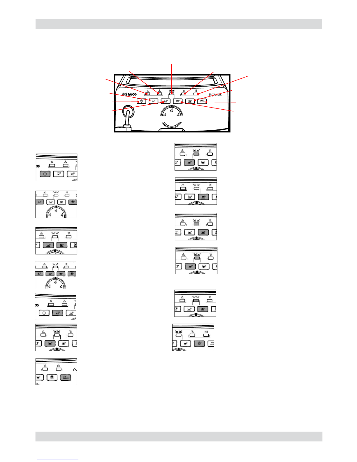
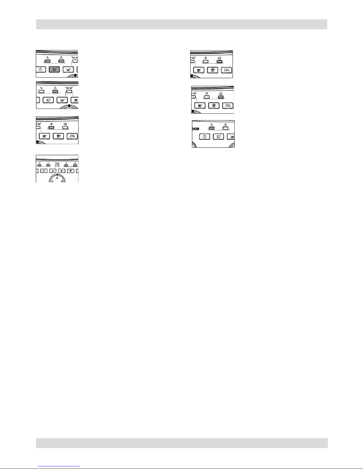
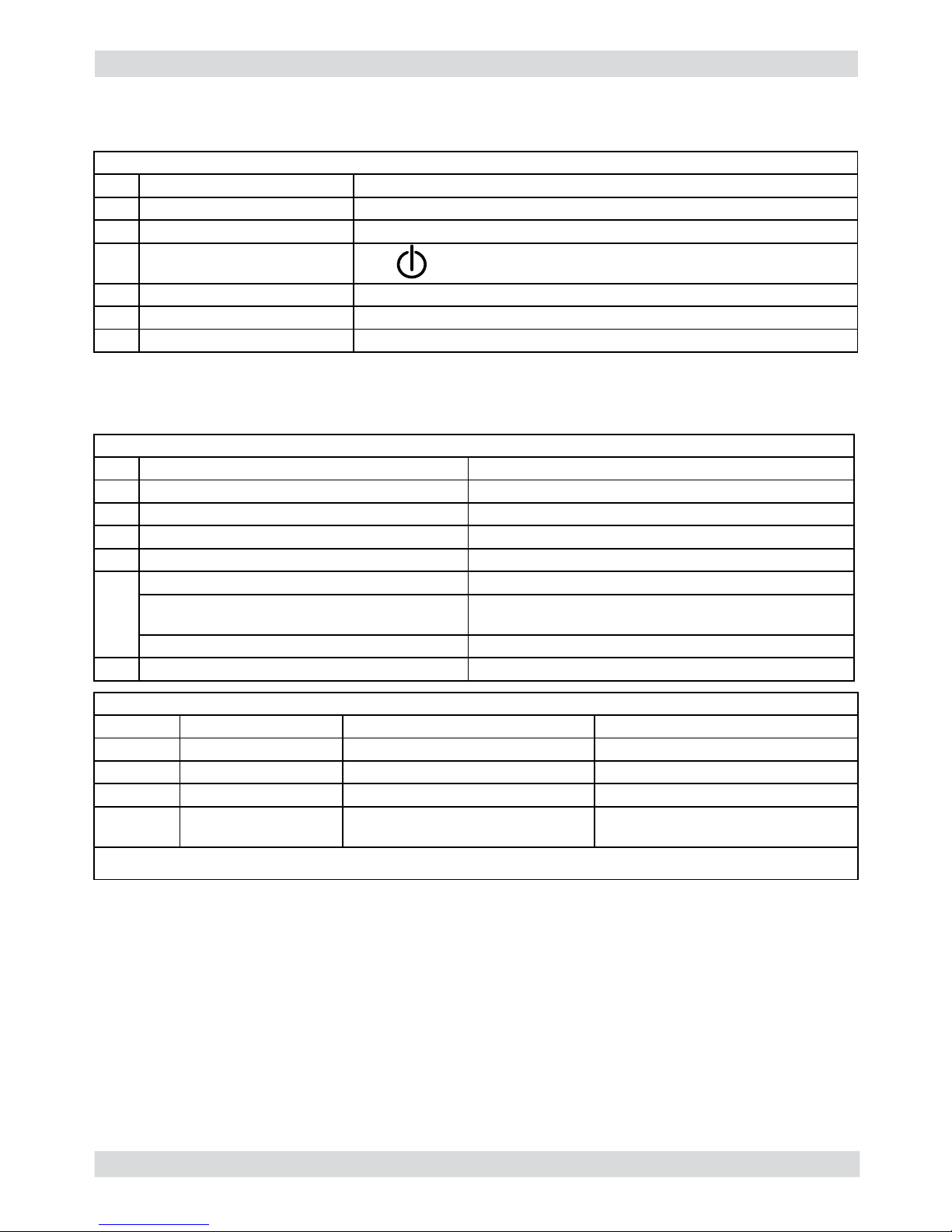
5.1.4. Intuita
Page 51

INTELIA 05 TROUBLESHOOTING
Saeco International Group Rev. 03 Page / 22
The user can switch the level by pressing the ON/OFF button, the machine shows the level of
the test:
a) Level 1: LED No Water
b) Level 2: LED No Water, LED Error
c) Level 3: LED No Water, LED Error, LED Double
d) Level 4 : LED No Water, LED Error, LED Double, LED No Beans
e) Level 5 : LED No Water, LED Error, LED Double, LED No Beans, LED Dump Box
TEST MODE Level 0
Pressing botton ON/OFF
TEST MODE Level 1
Pressing botton ON/OFF
TEST MODE Level 2
Pressing botton ON/OFF
TEST MODE Level 3
Pressing botton ON/OFF
TEST MODE Level 4
Pressing botton ON/OFF
TEST MODE Level 5
Pressing botton ON/OFF
TEST MODE Level 0
Pressing botton ON/OFF
17
Page 52

INTELIA 05 TROUBLESHOOTING
Saeco International Group Rev. 03 Page / 22
Level 0 (LED)
Description :
Verify keyboard LED
Action :
LED ON/OFF always blink during the test.
The others LED blink once, then only one LED is ON starting from No Water, Error, Double, No
Beans, Dump Box, Calc Clean, Steam, Coffee, Espresso, Hot Water.
The sequence is always repeated.
Note
LED COLOR
No Water RED
Error RED
Double GREEN
No Beans RED
Dump Box RED
Calc Clean YELLOW
Steam GREEN
Coffee GREEN
Espresso GREEN
Hot Water GREEN
ON/OFF RED
Pressing ON/OFF button moves to next level
On ERROR verify:
Cable connection
Power supply
Driver 74HC595 presence and welding
Driver 74HC595 orientation
LED presence and welding
LED orientation
Polarization resistor presence and welding
Level 1 (Buttons) [LED No Water ON]
Description:
Verify the keyboard buttons (each button has a rear LED)
Action:
Pressing the button where the rear LED is ON changes the LED OFF, follow the moving LED
If you are not able to turn the LED OFF detects an error condition over the button switch
Start condition
All LED are OFF
Pressing ON/OFF button moves to next level
On ERROR verify:
Cable connection
Power supply
Push button presence and welding
18
Page 53

INTELIA 05 TROUBLESHOOTING
Saeco International Group Rev. 03 Page / 22
Level 2 (switch) [LED No Water + Error ON]
Description:
Verify the security switch connection
Action:
Mechanical move the switch and verify the relative electrical feedback
Start condition (no water tank, no BU, no dump box, door open)
All LED are blinking (because every switch is OFF)
Closing every switch turns ON the LED
Switch LED
Water presence hot water
BU presence espresso
Door open coffee
Dump box steam
Press ON/OFF button moves to next level
On ERROR verify:
Cable connection
Power supply
Level 3 (Aroma trimmer) [LED No Water + Error + Double ON]
Description:
Verify the aroma trimmer
Action:
Rotate aroma trimmer, 3 position 3 LED
Start condition none
Aroma LED
1 bean hot water
2 beans hot water + espresso
3 beans hot water + espresso + coffee
Press ON/OFF button moves to next level
On ERROR verify:
Cable connection
Power supply
19
Page 54

INTELIA 05 TROUBLESHOOTING
Saeco International Group Rev. 03 Page / 22
Level 4 (Water Circuit) [LED No Water + Error + Double + No Beans ON]
Description:
Verify the water circuit component: fl ux meter, pump, electro valve, brewing unit
Action:
Turn on and off actuators along water and coffee beverage circuit.
LED ON/OFF Hot water Espresso Coffee Steam Calc clean
OK OFF OFF OFF OFF OFF OFF
LED ON/OFF Hot water Espresso Coffee Steam Calc clean
OK ON
LED ON/OFF Hot water Espresso Coffee Steam Calc clean
OK OFF
LED ON/OFF Hot water Espresso Coffee Steam Calc clean
During the test BLINK OFF
OK ON OFF
Work position not reached ON ON
Overcurrent (with or without BU) ON BLINK
LED ON/OFF Hot water Espresso Coffee Steam Calc clean
During test BLINK OFF
OK ON OFF
Home position not reached ON ON
Overcurrent (with or without BU) ON BLINK
LED ON/OFF Hot water Espresso Coffee Steam Calc clean
During the test BLINK OFF
OK ON OFF
ERROR (no fl ux meter feedback) ON ON
Press one time Hot Water button to open electro valve
Start condition (water tank full, BU, dump box, door closed)
Press one time Hot Water button to close electro valve
Move BU to work position. Press Coffee button to move BU to work position
Move BU to home position. Press Steam button to move BU to home position
Press Epresso button to turn on pump
LED ON/OFF Hot water Espresso Coffee Steam Calc clean
OK BLINK BLINK
Press ON/OFF button moves to next level
On ERROR verify:
Cable connection
Power supply
Move BU to rest position. Press Calc Clean button to move BU to rest position
20
Page 55

INTELIA 05 TROUBLESHOOTING
Saeco International Group Rev. 03 Page / 22
LED ON/OFF Hot water Espresso Coffee Steam Calc clean
OK OFF OFF OFF OFF OFF OFF
Start condition (water tank full, BU, dump box, door close)
LED ON/OFF Hot water Espresso Coffee Steam Calc clean
During the test BLINK OFF
OK ON OFF
ERROR NTC open or short circuit ON ON
LED ON/OFF Hot water Espresso Coffee Steam Calc clean
OK CURRENT SENSE > 1 A ON OFF
Heater already hot BLINK
ERROR CURRENT SENSE > 1 A ON OFF
LED ON/OFF Hot water Espresso Coffee Steam Calc clean
During the test BLINK OFF
OK ON OFF
No grinder rotation ON ON
Press ON/OFF button moves to next level (level 0)
On ERROR verify:
Cable connection
Power supply
Press once Hot Water button to check heater NTC sensor
Press Espresso button to check heater power on (you need current sense / measure)
Press Coffee button to check grinder rotation
Level 5 (Grinder & Heater)
[LED No Water + Error + Double + No Beans + Dump Box ON]
Description:
Verify temperature increase in the heater and grinder rotation
Action:
Turn on and off actuators
21
Page 56

INTELIA 05 TROUBLESHOOTING
Saeco International Group Rev. 03 Page / 22
ERROR
CODES
DESCRIPTION
01
The coffee grinder is blocked (grinder blades jammed or sensor not
reading properly)
03
The brewing unit is blocked in work position (microswitch not released
in up position after 3", torque error trying to move down, descent time
out exceeded)
04
The brewing unit is blocked in home position (microswitch not released
in down position after 3", torque error trying to move up, ascent time
out exceeded)
05
Water circuit / fl ow meter problems (water circuit blocked or no fl ow
meter signal)
10
Boiler temperature sensor short circuited
11
Boiler temperature sensor open circuit
14
The boiler temperature has exceeded the maximum allowed value
(165°c)
15
The boiler temperature has not increased by x°C in y sec (boiler power
supply disconnected, incorrect boiler fi tted must be a 1300W boiler, par-
tial power supply to boiler, cut out thermostat tripped)
19
Mains voltage trouble
5.2. Error codes
22
Page 57

Saeco International Group Rev. 03 INTELIA
Page 58

INTELIA 06 STANDARD CHECKS
Saeco International Group Rev. 03 Page / 02
01
Action
1 Visual inspection (transport damage)
2 Machine data check (rating plate)
3 Operational check / problem analysis
4 Opening machine
5 Visual inspection
6 Operational tests
7 Repairing the faults encountered
8 Checking any modifi cations (view Symptom Cure, new software, etc.)
9 Service activities in accordance with the operating schedule
10 Internal cleaning
11 Operational test while the appliance is open
12 Assembly
13 Final inspection test
14 Draining the circuit (in winter)
15 External cleaning
16 Lubricating the brewing unit with suitable grease
17 Insulation test HG 701 (dielectric)
18 Documentation
S Replacement P Cleaning
ES Visual inspection TR Noise test
D Descaling R Adjustment
Component Action Support/tool
Water fi lter P/S
Water tank lip seal S
Boiler pin O-ring S
Brewing unit ES/P Grease solvent / Grease
Hoses, attachments and Oetiker clamps ES
Pump ES/TR
Gear motor ES/TR
Coffee grinder P/R Vacuum cleaner / brush
Water circuit D Saeco descaler
Hot water/steam valve ES/S
6.2. Service schedule
6.1. Repair schedule
Page 59

INTELIA 06 STANDARD CHECKS
Saeco International Group Rev. 03 Page / 02
02
Test Procedure
Support/
tool
Standard Tolerance
Espresso
2-3 Espressos for
adjustment purposes
Measuring
scoop
Same amount 15%
Coffee
2-3 Coffees for
adjustment purposes
Measuring
scoop
Same amount 15%
Noise Standard
Amount of
cream
Blow into the cup until
the cream separates
The cream should
come together
again to form a
complete layer
Cream colour Hazel brown
Temperature
Reading taken while
dispensing
Thermometer 84 ˚C ± 4 ˚C
Grinding level
Check the grain size of
the ground coffee
Hot water Dispense water
Steam Dispense steam
Dreg drawer
missing
indication
Remove the dreg drawer
Dreg drawer
missing indication
Low bean level
indication
Start brewing a coffee
while the coffee bean
hopper is empty
Low bean level
indication
6.3. Final test
Page 60

Saeco International Group Rev. 03 INTELIA
Page 61

INTELIA 07 DISASSEMBLY
Saeco International Group Rev. 03 Page / 11
7.1. Intelia Cappuccino outer Shell
Remove the water tank, coffee container cover, drip tray, dreg drawer,
brewing unit, carafe or hot water
dispenser.
Unscrew the screws shown
and remove the fi nger
protection.
Lift the top cover. Unscrew the screws shown
and slide out the left side
body.
Loosen the screws as illustrated, slide out the rear body and the sound insulating cover of the
coffee grinder.
01
Slide out the hatch.
Page 62

INTELIA 07 DISASSEMBLY
Saeco International Group Rev. 03 Page / 11
7.2. Intellia Class and Focus outer Shell
Remove the water tank, coffee container cover, drip tray, dreg drawer,
brewing unit, cappuccino maker or
pannarello.
Unscrew the marked
screws and remove
the fi nger protection.
Raise the top
cover.
Loosen the screws as illustrated
and remove the left side body.
Loosen the screws as illustrated, slide out the rear body and the sound insulating cover of the
coffee grinder.
7.3. Coffee grinder
Loosen the screws as illustrated and remove the sound
insulating cover. Raise the coffee grinder and remove
the connections.
When reassembling the coffee grinder,
make sure the spring is repositioned
correctly (see photo).
Slide out the hatch.
02
Page 63

INTELIA 07 DISASSEMBLY
Saeco International Group Rev. 03 Page / 11
03
To extract the top support of the appliance, press
on the grinding adjustment spindle (A) and turn the
support anticlockwise until it unhooks.
Turn the grinder blades anticlockwise out of the support.
Turn the grinder blades clockwise out of the support. The
bayonet connections can be accessed from the rear.
For a standard adjustment, both markings must be
aligned.
7.4. Grinder blades
A
B
Page 64

INTELIA 07 DISASSEMBLY
Saeco International Group Rev. 03 Page / 11
04
The grinding adjustment can be set by the user (only with the coffee grinder in operation) by
pressing and turning (only by one click at a time) the insert inside the coffee bean hopper with the
aid of the wrench supplied.
1) Loosen the screws holding the front plate to the upper plate
2) Remove the front plate, pressing it in the center and pulling the side walls outward
3) Remove the board support assembly
4) Loosen the screws holding the solenoid valve to the upper plate
5) Disconnect all electrical and water circuit connections
Adjustment by a service center
7.5. Coffee grinder adjustment
7.6. Intelia Cappuccino three-way solenoid valve
+
-
+
-
C
1
2
3
4
4
5
To adjust grinding further, the engineer can work directly on the coffee
grinder by pressing and turning the ring nut (C) shown. (clockwise + to
increase the particle size of the coffee and anticlockwise - to decrease it).
If there are any remains of coffee powder between the two grinding
blades it is recommended to tighten by max. two marks at a time.
Lastly, move the arrow (A) on the adjustment knob to the center of the
adjustment dots on the cover (B).
Page 65

INTELIA 07 DISASSEMBLY
Saeco International Group Rev. 03 Page / 11
1) Loosen the screws holding the front plate to the upper plate.
2) Remove the card support assembly.
3) Loosen the screws holding the solenoid valve to the upper plate.
4) Disconnect all electrical and water circuit connections.
7.7. Intelia Class and Focus two-way solenoid valve
2
3
4
1
1) Loosen the screws holding the front cover of the carafe fi tting body and release it from its seat
2) Loosen the screws as illustrated
3) Remove carafe presence sensors
4) Remove carafe fi tting Tefl on pipe
7.8. Intelia Cappuccino carafe fi tting body
05
1
3
2
2
2
3
3
4
Page 66

INTELIA 07 DISASSEMBLY
Saeco International Group Rev. 03 Page / 11
7.9. Pump
7.10. Flow-meter
Lift the fl ow meter out of the casing assembly and
remove the electrical and water circuit connections.
Loosen the screws as
illustrated, slide out the
electrical connection and
remove the card guard.
Slide the card off the
support and disconnect the
electrical connections.
Disconnect the water circuit connections (A) and
electrical connections (B), loosen the safety valve
(C) and slide the pump off the brackets (D).
06
7.11. Control board
A
B
D
D
C
A
A
7.12. Water sensor control board
Slide the card off the
support.
Slide out the pipe
connecting the fl ow
meter to the pump.
Loosen the screw as illustrated and
remove the capacitive sensor glued to
the seat.
Page 67

INTELIA 07 DISASSEMBLY
Saeco International Group Rev. 03 Page / 11
7.13. Gear motor
Only for Intelia Cappuccino remove the plug body along with pitcher
Unscrew the screws (highlighted) and
release the milk jug plug body assembly
Unscrew the screws in the front cover and lift
it off the milk jug plug body from the place
07
Unscrew the screws as illustrated and remove the front panel to
access the screws which fi x the dispenser cover into place.
Slide out the fork as illustrated.
Unscrew the screws shown and
remove the fi nger protection.
Lift the top cover.
Unscrew the screws shown
and slide out the left side
body.
Page 68

INTELIA 07 DISASSEMBLY
Saeco International Group Rev. 03 Page / 11
08
Loosen the screws as illustrated and
remove the gear motor cover.
The following are located inside the compartment protected by the casing:
- Electric motor (A) with gears (B) and (C) for transmission and timing of the dispenser.
- Dreg drawer presence sensor (D).
- Brewing unit present microswitch (E).
- Microswitch (F) detecting brewing unit home and
work positions.
- Remove the gear (C) that meshes with the motor
transmission shaft.
- Remove the large gear (B).
- Remove the motor (A), complete with transmission
shaft.
Loosen the screws as illustrated and
remove the boiler pin (A).
Replace the gear (B), making sure that the imprint of
the arrow is aligned with the opening containing the
pin (P).
When replacing the motor and the transmission shaft,
make sure the guide runners (L) are in the right position.
Grease the shaft thoroughly and evenly.
A
B
D
E
F
C
H
L
B
P
A
Page 69

INTELIA 07 DISASSEMBLY
Saeco International Group Rev. 03 Page / 11
09
7.15. Dispenser assembly
7.16. Valve disassembly
7.14. Boiler
Unscrew the marked screw and disconnect the
electrical and water circuit connections.
Loosen the screws as illustrated and remove the front panel to
access the screws which fi x the dispenser cover into place.
Press the hooks as illustrated and slide out the dispenser assembly.
Slide out the fork as illustrated.
Release the boiler cover
and take it off.
Loosen the screws as illustrated and remove the front panel to
access the screws which fi x the dispenser cover into place
Loosen the screws as
illustrated and remove the
boiler pin (A)
A
Page 70

INTELIA 07 DISASSEMBLY
Saeco International Group Rev. 03 Page / 11
7.17. Control board and display
Loosen the screws as illustrated
and remove the front panel.
Disconnect the electrical connections
and unhook the card support.
Loosen the screws as
illustrated.
Remove the frame from
the keypad and the
display.
Remove the electrical connections between the card and the
display and release the card from the support.
Loosen the screws as
illustrated.
10
Loosen the screws as illustrated and release the insert in the bottom of the body to obtain easy
access for valve disassembly
Loosen the screws as illustrated,
remove the hydraulic connections
and take out the valve
Page 71

INTELIA 07 DISASSEMBLY
Saeco International Group Rev. 03 Page / 11
Use a suitable pair of pliers to remove the
clamp (as illustrated).
Tighten the clamp as illustrated.
1) Boiler connection.
2) Other connections.
7.18. Fitting and removing Oetiker clamps
11
Page 72

Saeco International Group Rev. 03 INTELIA
Page 73

INTELIA 08 NOTES
Saeco International Group Rev. 03 Page / 01
01
Page 74

Saeco International Group Rev. 03 INTELIA
Page 75

INTELIA 09 WATER CIRCUIT DIAGRAM
Saeco International Group Rev. 03 Page / 01
01
Flow meter
Turbina
Water tank
Serbatoio
acqua
Silicone tube
Tubo silicone
Silicone tube
Tubo silicone
Silicone tube
Tubo silicone
Silicone tube
Tubo silicone
Assy Solenoid valve
Assieme Elettrovalvole
4 bar Valve
Valvola 4 bar
Water drain
Scarico acqua
Water drain
Scarico acqua
Pump
Pompa
Boiler
Caldaia
Jug
connection
Safety valve
Valvola di sicurezza
Intelia Cappuccino
Silicone tube
Tubo silicone
Silicone tube
Tubo silicone
Tefl on tube
Tubo Tefl on
Silicone tube
Tubo silicone
Silicone tube
Tubo silicone
Silicone tube
Tubo silicone
Brew unit
Gruppo caffè
Boiler pin
Perno caldaia
Page 76

INTELIA 09 WATER CIRCUIT DIAGRAM
Saeco International Group Rev. 03 Page / 01
02
Flow meter
Turbina
Water tank
Serbatoio
acqua
Silicone tube
Tubo silicone
Silicone tube
Tubo silicone
Silicone tube
Tubo silicone
Silicone tube
Tubo silicone
Silicone tube
Tubo silicone
Silicone tube
Tubo silicone
2 way Solenoid valve
Elettrovalvola a due vie
Silicone tube
Tubo silicone
4 bar Valve
Valvola 4 bar
Water drain
Scarico acqua
Boiler pin
Perno caldaia
Brew unit
Gruppo caffè
Pump
Pompa
Boiler
Caldaia
Steam pipe
Tubo vapore
Safety valve
Valvola di sicurezza
Intelia Focus and Class
Page 77

Saeco International Group Rev. 03 INTELIA
Page 78

INTELIA 10 WIRING DIAGRAM
Saeco International Group Rev. 03 Page / 01
01
Intelia Focus and Class
 Loading...