

Page 1
Service Manual
Revision 01 December 2012
All parts of this document are the property of Saeco International Group.
All rights reserved. This document and all the information herein is provided without liability deriving from any errors or omissions. Furthermore, no part may be reproduced,
used or collected, except where express authorisation has been provided in writing or through a contractual agreement.
Published by Saeco International Group Subject to modifi cation EN 4219 400 00012
Service
Co ee Machine
RI 9933
Gaggia Unica
Table of contents Page
1. Introduction
1.1. Documentation required 1
1.2. Tools and equipment required 1
1.3. Material 1
1.4. Safety warnings 1
1.5
Service POLICY 2
1.6.1. External machine parts 3
1.6.2. Internal machine parts 4
2. Technical specifi cations
2.1. Technical specifi cations 1
2.2 Specifi cation for the measurement of the coffee
products temperature.
2
2.3. Machine parameters and performance 3
3. User instructions
3.1. Customer and programming menu 1
3.2. Machine indications 2
3.3. Operation, cleaning and maintenance 3
4. Operating logic
4.1. Water circuit 1
4.2. Coffee cycle 2
4.3. Single microswitch 3
4.4. Temperature sensor 3
4.5. Coffee grinder 4
4.6. Low bean level detection, dose quantity adjustment,
coffee grinder blocked
4
Table of contents Page
4.7. Dose self-learning (SAS) 5
4.8. Water level detection (water tank) 6
4.9. Water level detection (drip tray) 6
4.10. Descaling request 7
4.11. Water fi lter 7
5. Troubleshooting
5.1. Test mode 1
5.2. Error messages 3
6. Standard checks
6.1. Repair schedule 1
6.2. Service schedule 1
6.3. Final test 2
7. Disassembly
7.1. Outer elements 1
7.2. Coffee grinder 1
7.3. Grinder blades 2
7.4. Coffee grinder adjustment 3
7.5. Pump 4
7.6 Turbine 4
7.7 Power card 4
7.8 Caldaia 4
7.9 Gearmotor 5
2011-June-08
Page 2

Saeco International Group Rev. 01 GAGGIA UNICA
Table of contents Page
7.10. Cock card and hot water/steam cock 6
7.11. Dispenser assembly 6
7.12. CPU and display card 6
7.13. Fitting and removing Oetiker clamps 7
8. Notes
9. Water circuit diagram
10 Electrical diagram
Page 3
Saeco International Group Rev. 01 GAGGIA UNICA
Page 4
GAGGIA UNICA 01 INTRODUCTION
Saeco International Group Rev. 01 Page / 04
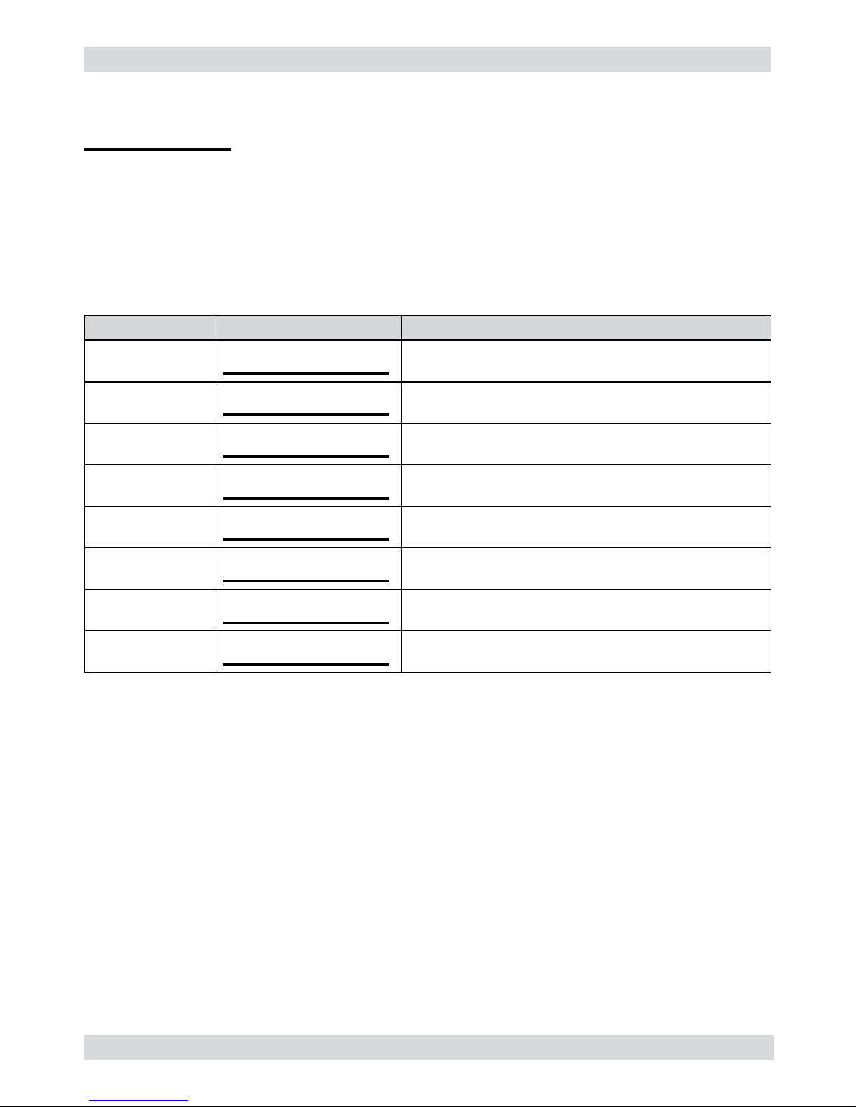
1.1 Documentation required
The following documentation is needed for repair procedures:
• Instruction booklet for specifi c model
• Technical documentation for specifi c model (diagrams, exploded drawings)
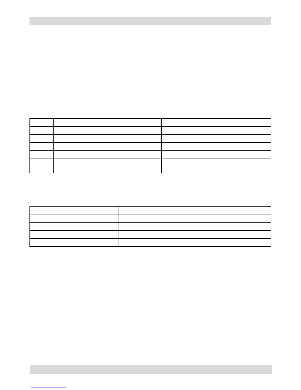
1.2 Tools and equipment required
As well as the standard equipment, the following is required:
Qty. Description Notes
1 Screwdriver Torx T 8 - T 10 - T 20
1 Pliers for Oetiker clamps
1 CC -A - Vdc tester
1 Digital thermometer Scale limit > 150°C
1 SSC (Saeco Service Center) Programmer
(for programming and diagnostics mode)
1.3 Material
Description Notes
Thermal paste Heating element > 200°C
Descaler Saeco descaler
Grease solvent Personal choice
Silicone grease Safe to use with food
1.4 Safety warnings
We recommend you consult the technical manual of the machine before performing any
maintenance work.
Observe all applicable standards relating to the repair of electrical appliances.
Always disconnect the power plug from the mains before beginning repair work.
Simply turning off the main machine power switch is not an adequate safety precaution.
This domestic appliance is rated as insulation class I.
On completion of the repair work, insulation and dielectric rigidity tests must be performed.
01
Page 5
GAGGIA UNICA 01 INTRODUCTION
Saeco International Group Rev. 01 Page / 04
02
Components Assembly use Single components available
COFFEE
GRINDER
Only for OOW repairs
YES, to consult the specifi c exploded-view of the
machine or of the Coffee Grinder on website
BREWING
UNIT
Only for OOW repairs
YES, to consult the specifi c exploded-view of the
machine or of the Brewing unit on website
BOILER Only for OOW repairs
YES, to consult the specifi c exploded-view of the
machine on website
GEAR
MOTOR
Only for OOW repairs
YES, to consult the specifi c exploded-view of the
machine on website
FILTER
HOLDER
Only for OOW repairs
YES, to consult the specifi c exploded-view of the
machine on website
MILK
CARAFE
Only for OOW repairs
YES, to consult the specifi c exploded-view of the
machine on website
THERMAL
CARAFE
Only for OOW repairs
YES, to consult the specifi c exploded-view of the
Thermal Carafe on website
MILK ISLAND Only for OOW repairs
YES, to consult the specifi c exploded-view of the
Milk Island on website
1.5 Service POLICY grid as used for coffee machine
List of principal assembly present in all our coffee machines
For IN WARRANTY repairs is mandatory to use the single components (not the assembly) avai-
lable in the exploded views of the coffee machines or of the specifi c components. If you fi nd the
information “SEE THE EXPLODED VIEW E........” in the assembly description fi eld, it means that
the single components of the assembly are available in the other pages of the exploded view. It’s
possible to use the assembly only if there is a specifi c Symptom Cure that include this possibility
or when the single components are not available for the order.
Page 6
GAGGIA UNICA 01 INTRODUCTION
Saeco International Group Rev. 01 Page / 04
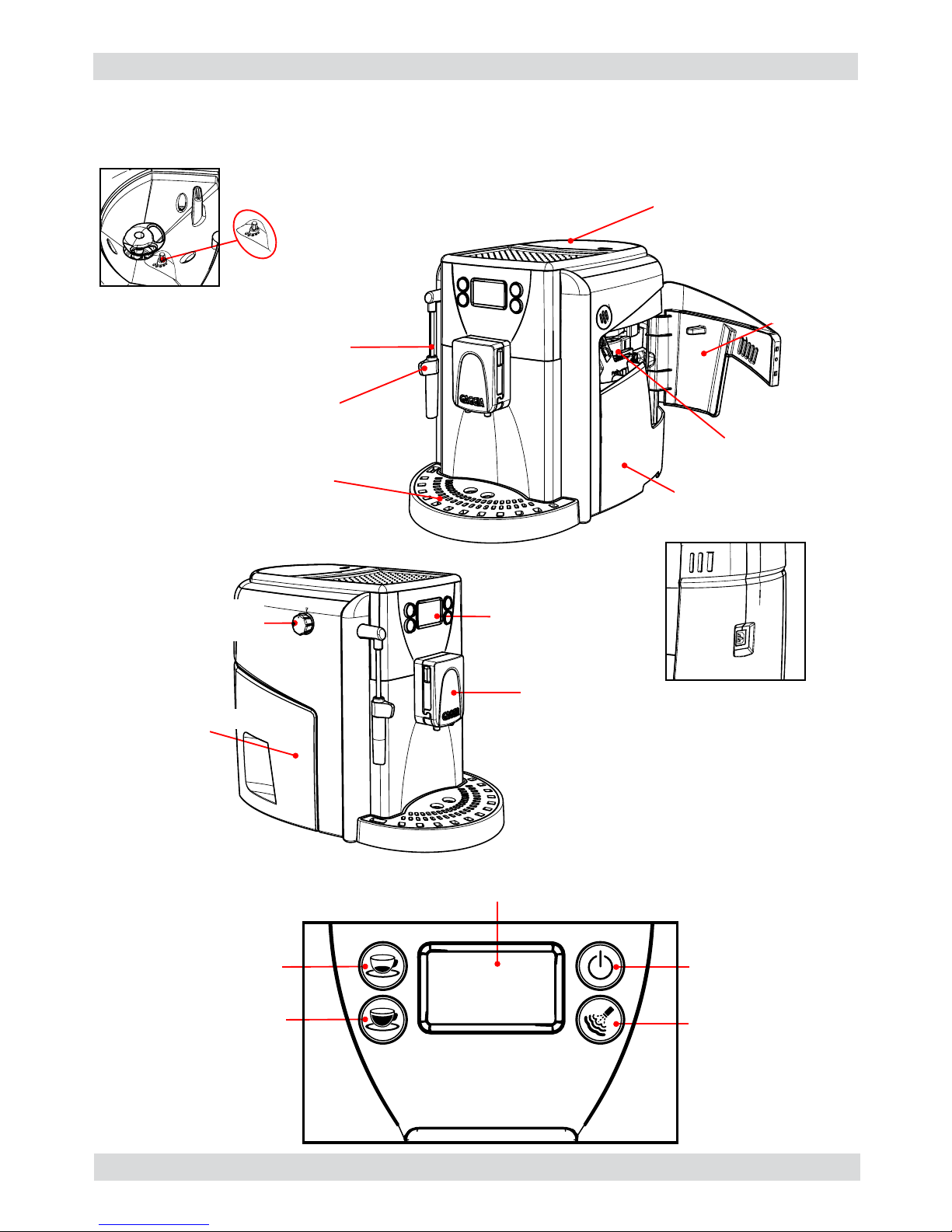
1.6.1 External machine parts
03
Drip
tray+grille
Coffee bean hopper
with lid
Hot water/steam
dispensing pipe
Dispensing pipe
protection
Brewing unit
Dreg drawer
Power supply socket
Grinding
adjustment
Water tank
Control panel
Coffee
dispenser
Service
hatch
Hot water/steam
dispensing knob
LED display
Espresso
dispensing button
ON/OFF button
steam selection
button
Long coffee
dispensing button
Page 7
GAGGIA UNICA 01 INTRODUCTION
Saeco International Group Rev. 01 Page / 04
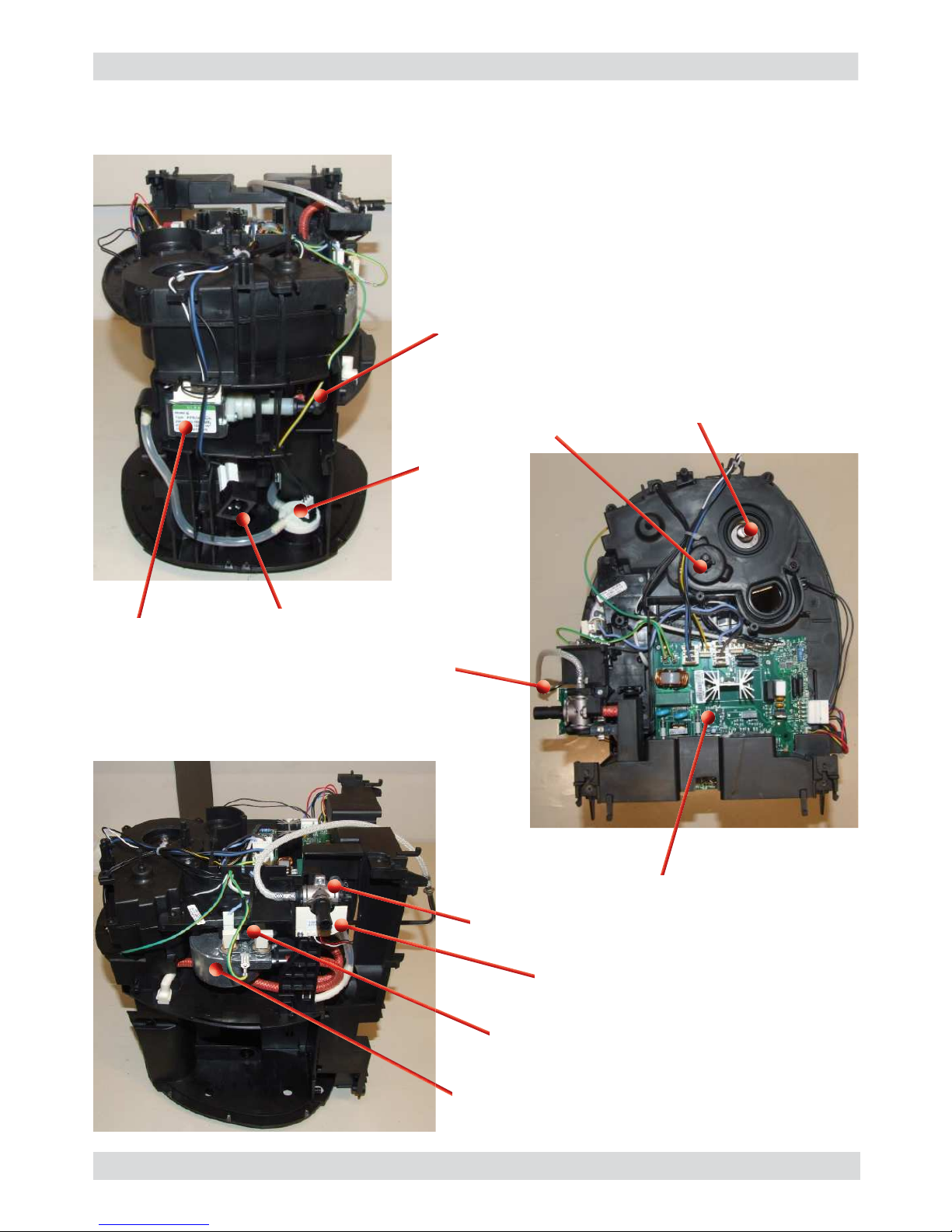
1.6.2 Internal machine parts
04
Pump
Turbine
Boiler
Thermostats
Hot water/steam valve
Hot water /steam cock card
Power card
Coffee grinder
Grinding
adjustment insert
Steam pipe
Power cable connector
Safety valve
Page 8
Saeco International Group Rev. 01 GAGGIA UNICA
Page 9
GAGGIA UNICA 02 TECHNICAL SPECIFICATIONS
Saeco International Group Rev. 01 Page / 04
2.1. Technical specifi cations
Power supply and output: 240 V~ 50 Hz 1400 W - 230 V~ 50/60 Hz 1400 W -
120 V~ 60 Hz 1500 W - 100 V~ 50/60 Hz 1300 W
Temperature monitoring: (NTC) variable resistor sensor - transmits the value to the
electronic card
Safety system:
2 thermostats at 175°C one shot
Coffee heat exchanger output:
Stainless steel
(230/120 V~) 1300 W – (100 V~) 1100W
for coffee, hot water and steam dispensing
Steam heat exchanger output:
Stainless steel
As above
Gearmotor: 2 rotation directions; power supply 24VC
Pump Ulka Type EP5/S GW approx. 13-15 bar with reciprocating
piston and thermal switch 100°C 48 W, 230V, 50 Hz, 120V,
60Hz 100V, 50/60 Hz
Overpressure valve: Opening at approx. 18-20 bar
Water fi lter: In tank
Coffee grinder: Direct current motor with fl at ceramic grinder blades
Automatic dosage Dose adjustment controlled by the electronic system
Power consumption: During heating phase- approx. 5.6 A
Dimensions: W x H x D in mm: 320x372x461
Weight: 9 kg
Water tank capacity: 1.7 l.
Coffee bean hopper capacity 250 g. of coffee beans
Dreg drawer capacity 14
Heat exchanger capacity: Approx. 10 cc
Water circuit fi lling time: Approx. 15 sec Max. on fi rst fi lling cycle
Heating time: Approx. 45 sec.
Grinding time: Approx. 8-10 sec.
01
Page 10
GAGGIA UNICA 02 TECHNICAL SPECIFICATIONS
Saeco International Group Rev. 01 Page / 04
02
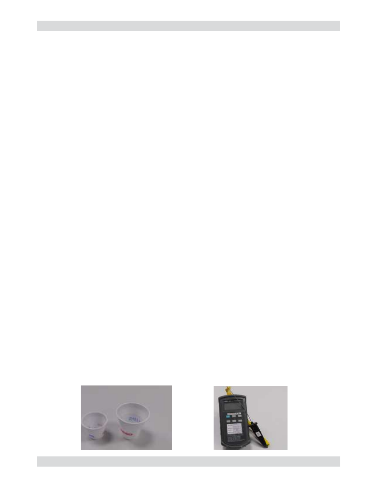
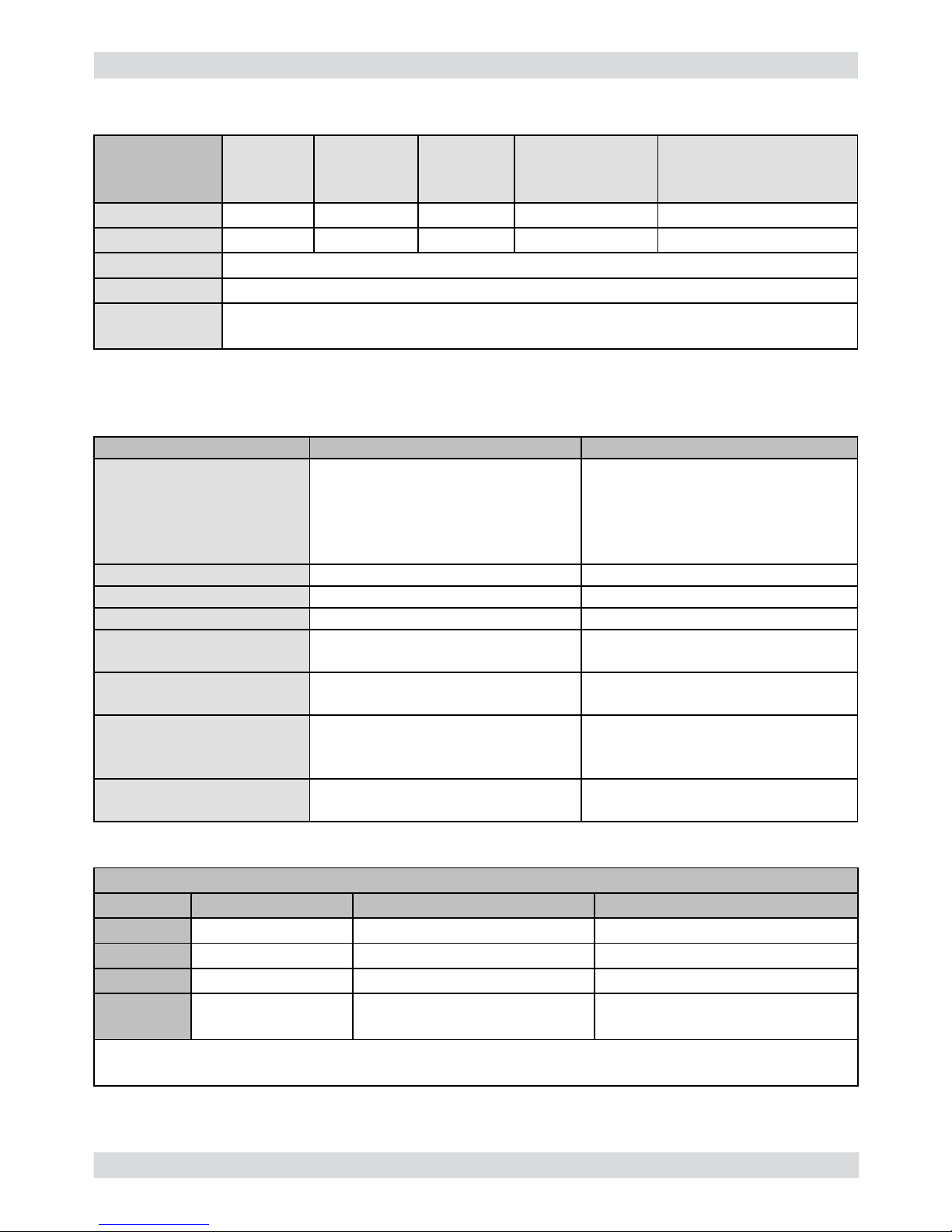
2.2. Specifi cation for the measurement of the coffee products temperature.
The temperature is infl uenced by the fl ow from the dispenser and stratifi cation of temperatures in
the glass. In order to consider these phenomena and to introduce measures that allow comparisons in controlled conditions, below guidelines must be followed:
Conditions:
a) Water temperature in tank: 23°C (+/-2°C).
b) It must be used a plastic cup (see picture N°1).
c) It must be used a thermocouple thermometer (e.g. type K - see picture N°2).
d) The coffee machine is tested without any change of parameters or calibrations, which may
affect the temperature of products, so the measurement of temperature must be done with
machine in default factory setting.
Procedure:
1. The temperature must be measured in the cup, immediately after dispensing. Cup has to be
placed on a non-metal surface using a thermocouple thermometer.
2. The temperature in the cup is measured by immersing the probe of the thermometer up to
touch the bottom.The probe then must be moved in a circular motion for 5/6 rotations. At the
of the rotations, stop in the center of the cup.
3. The highest temperature measured during the rotations is the value we are searching for, and
that must be reported;
4. Test measurement: from end of dispensing to the end of rotations must be completed within 12
seconds.
Limits of acceptability
The acceptance limits are divided by features and products and are the following:
Espresso Coffee Italy Q.ty 25/40 gr.
Temperature of 1st product 69°C ≤ 85°C
Temperature of 2nd product 72°C ≤ 85°C
Coffee Q.ty 70/120 gr.
Temperature of 1st product 69°C ≤ 85°C
Temperature of 2nd product 72°C ≤ 85°C
Picture 1
Picture 2
Page 11
GAGGIA UNICA 02 TECHNICAL SPECIFICATIONS
Saeco International Group Rev. 01 Page / 04
2.3. Machine parameters and performance
PRODUCT
QUANTITY
Minimum
quantity
(Puls.)
Default
quantity
(Puls.)
Maximum
quantity
(Puls.)
User
programmable
Programm. by
Production / Service
Espresso 50 130 - 170 600 Yes No
Long coffee 70 200 - 230 600 Yes No
Pre-ground No
Hot water Continues for 400 pulses
Steam for
frother
Continues until the water supply has been exhausted (capacitive sensor)
RINSE Initial rinse Final rinse
When performed When the machine is switched
on and the boiler temperature is
≤ 50°C
When the machine is switched
off electronically, manually or
automatically after 60', if at least
one coffee has been dispensed,
before switching off
No. of pulses 130 100
Stopping option Yes, by pressing any key Yes, by pressing any key
User disable option No No
Production/Service
department disable option
No No
No. of pulses user
adjustment option
No No
No. of pulses Production/
Service department
adjustment option
No No
Pulse range
(Min. – Max.)
No No
03
Descaling cycle frequency
Hardness Water hardness Without water fi lter With water fi lter
1 Soft (up to 7°dH) 240 litres (480,000 pulses) 480 litres (960,000 pulses)
2 Medium (7°-14dH) 120 litres (240,000 pulses) 240 litres (480,000 pulses)
3 Hard (15°-21°dH) 60 litres (120,000 pulses) 120 litres (240,000 pulses)
4 Very hard
(over 21°dH)
30 litres (60,000 pulses) 60 litres (120,000 pulses)
The default water hardness level is 3. Each litre of water corresponds to approximately 2,000
pulses
Page 12
GAGGIA UNICA 02 TECHNICAL SPECIFICATIONS
Saeco International Group Rev. 01 Page / 04
WATER TANK Description
Water reserve (pulses) with water fi lter 200
Water reserve (pulses) with no water fi lter 200
Water reserve modifi able by Production/Service
departments
No
"Fill tank" alarm Yes
"No tray" alarm Yes
Water mains No
DREG DRAWER Description and values
Time-out for dreg drawer
5 sec.
Warning to empty dreg drawer after
Yes, after 14 lots of dregs
Reset dreg counter
The dreg drawer must be emptied only
when prompted by the machine ensuring
the machine is switched on and removing
the drawer for more than 5 seconds.
STANDBY Description and values
Inlet time (default) 60 minutes
Inlet time programmed by Production/
Service department
Yes
Boiler temperature during Standby Boiler OFF
04
Page 13
Saeco International Group Rev. 01 GAGGIA UNICA
Page 14
GAGGIA UNICA 03 USER INSTRUCTIONS
Saeco International Group Rev. 01 Page / 03
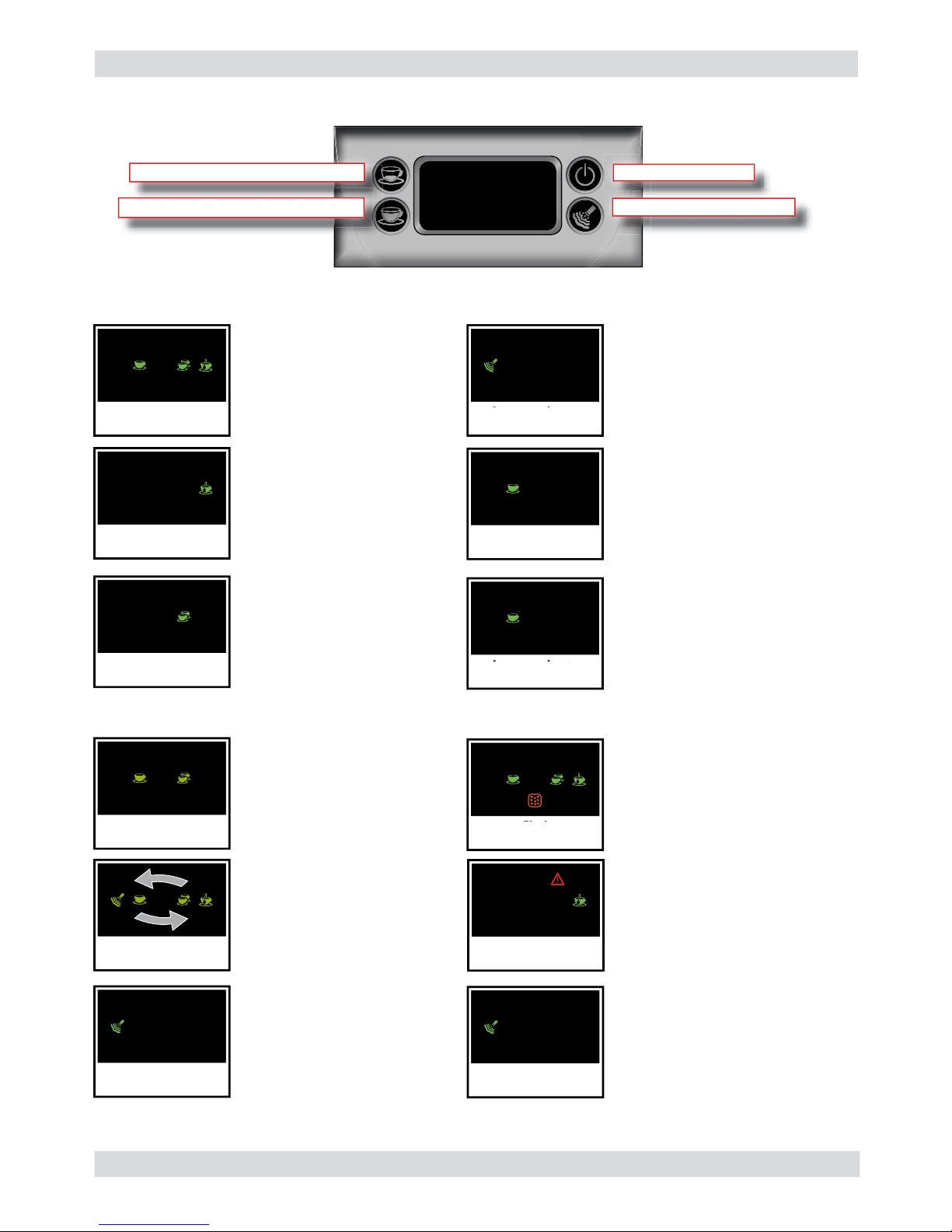
3.1. Customer and programming menu
Machine ready for dispensing
coffee with coffee beans and hot
water
Machine dispensing steam
Machine dispensing hot water
Machine dispensing espresso or
long coffee
Machine dispensing two espressos
or two long coffees
Machine in pre-heating phase
for coffee, hot water and steam
dispensing.
Machine in rinsing phase. Wait for
the machine to end the operation
Machine in steam heating phase
Machine overheated.
Dispense water to take the
machine to the ideal temperature
for dispensing coffee and hot
water
Machine ready signals
Notice signals
01
Lampeggianti
in ciclo
BLINKING
IN CYCLE
Fissi
STEADY
Fisso
STEADY
Fisso
STEADY
Fisso
STEADY
Fisso
STEADY
Lampeggianti
BLINKING
Lampeggianti
BLINKING
Lampeggiante
BLINKING
ON/OFF button
Steam selection button
Long coffee dispensing button
Espresso dispensing button
The machine is being
programmed with the coffee cup
fi ll level
The appliance requires a descaling
cycle
The machine requires a water
circuit fi lling cycle
Lampeggiante
BLINKING
Lampeggiante
veloce
BLINKING
FAST
Fisso
BLINKING
Page 15

GAGGIA UNICA 03 USER INSTRUCTIONS
Saeco International Group Rev. 01 Page / 03
02
Alarm signals
Fisso
STEADY
Lampeggiante
BLINKING
Lampeggiante
veloce
BLINKING
FAST
Fisso
STEADY
Lampeggiante
BLINKING
Fisso
STEADY
Fisso
STEADY
Turn the hot water/steam valve
knob to the correct position
- The Brewing unit must be inserted
in the machine.
- Close the service door
- Empty the dregs drawer
- Empty the tray under the unit
- No beans inside the coffee
container.
After fi lling the container, the cycle
can be restarted.
Switch off the machine and
carefully clean the dispensing
unit.
Insert the dregs drawer
Fill the water tank
3.2. Machine indications
Page 16

GAGGIA UNICA 03 USER INSTRUCTIONS
Saeco International Group Rev. 01 Page / 03
CLEANING AND TECHNICAL SERVICING
A Empty the dregs drawer When indicated
B Empty the drip tray As necessary
C Clean the water tank Weekly
D Clean the coffee bean hopper As necessary
E Clean the casing As necessary
F
Clean the brewing unit Every time the coffee bean hopper is fi lled or weekly
Lubricate the brewing unit After 500 dispensing cycles or when the grease is no
longer present on the brewing unit
Clean the unit housing Weekly
H Descaling When indicated
Descaling cycle frequency
Hardness Water hardness Without water fi lter With water fi lter
1 Soft (up to 7°dH) 240 litres (480,000 pulses) 480 litres (960,000 pulses)
2 Medium (7°-14dH) 120 litres (240,000 pulses) 240 litres (480,000 pulses)
3 Hard (15°-21°dH) 60 litres (120,000 pulses) 120 litres (240,000 pulses)
4 Very hard
(over 21°dH)
30 litres (60,000 pulses) 60 litres (120,000 pulses)
The default water hardness level is 3. Each litre of water corresponds to approximately 2,000 pulses
3.3. Operation, cleaning and maintenance
Operating the machine
1 Fill water tank
2 Fill the coffee bean hopper
3 Switch on the appliance
4
Press the key to switch the
machine on
5 Heating When the heating phase begins, wait for it to fi nish
6 Rinse Carry out a rinse cycle for the internal circuits
7 Machine ready The machine is ready to dispense beverages
03
Page 17

Saeco International Group Rev. 01 GAGGIA UNICA
Page 18

GAGGIA UNICA 04 OPERATING LOGIC
Saeco International Group Rev. 01 Page / 07
4.1. Water circuit
01
FLOW METER
WATER TANK
STEAM/WATER DISPENSING
BOILER 1300W
PIN FOR BOILER
STEAM/WATER FAUCET
WATER DESCHAGE IN THE WATER TANK
WATER DESCHAGE IN THE WATER TANK
PUMP
SAFETY VALVE
HOT WATER
WATER
HOT WATER/STEAM
Page 19

GAGGIA UNICA 04 OPERATING LOGIC
Saeco International Group Rev. 01 Page / 07
Notes: * Only with Pre-brewing
4.2. Coffee cycle
Switching on
When the machine is switched on, the gearmotor repositions itself as follows:
- It acts on microswitch 1 (see following chapter)
- The gearmotor changes its rotation direction and moves upwards again by approx. 1-2 mm
- The boiler begins to heat the water for approx. 45 sec., at full power, in order to reach the
optimal temperature. The temperature will then remain at a constant level.
Coffee cycle
1. The coffee grinder starts the grinding process (controlled by pulses generated by a sensor)
2. The gearmotor (brewing unit) moves to the dispensing position
3. Preliminary dispensing phase (short pump activity, short pause)
4. Product dispensing (the pump operation period is defi ned by the amount of product dispensed)
5. The gearmotor moves to its home position (the dregs are expelled automatically)
Main switch ON START STOP
Time
Coffee grinder
Heating
Pump
Brewing unit gear
motor
Status Heating Ready Coffee cycle
Pulses
(Dosage)
Pump operation
(turbine pulses) in
accordance with the
amount of product
selected
approx. 45 sec.
*
02
OFF
Single microswitch gearmotor
ON
Status
Microswitch
Page 20

GAGGIA UNICA 04 OPERATING LOGIC
Saeco International Group Rev. 01 Page / 07
An NTC is used as a temperature sensor; in the event of overheating this reduces boiler
element power consumption.
The electronic system detects the current boiler temperature from the drop in voltage of the
sensor and adjusts it accordingly.
Heating element values and corresponding temperatures: see table
4.4. Temperature sensor (adjustment)
Temp. (°C) R nom (kΩ) ΔR (+/- %)
20 61.465 8.6
50 17.599 5.9
75 7.214 4.1
80 6.121 3.7
85 5.213 3.4
90 4.459 3.1
100 3.3 2.5
125 1.653 3.9
150 0.893 5.1
4.3. Single microswitch
The gearmotor is powered by a direct current
motor that engages with the smaller double
toothed wheel using a worm screw. The
unit is mounted on the axle of the large
gear wheel and when a coffee is requested,
it moves from the standby position to the
dispensing position, and then back to the
standby position again.
- Standby position: 1
- Dispensing position: 2
2
1
03
Page 21

GAGGIA UNICA 04 OPERATING LOGIC
Saeco International Group Rev. 01 Page / 07
4.5. Coffee grinder
2
3
4
5
6
1
4.6. Low bean level detection, dose quantity adjustment, coffee grinder
blocked
Without beans n=100%
With beans n=100%
Without beans n=50%
With beans n=50%
The coffee grinder is driven by a direct current motor (1) using a worm screw helicoidal wheel
transmission (2).
The worm screw (2) drives a plastic gear wheel (3), which turns the lower grinder (4) and the
increment pin (5)
There are two magnets (6) in the gear wheel; at every rotation these induce two pulses to a Hall
sensor, which in turn transmits them to the electronic system.
No coffee
A low coffee bean level is detected by the Hall sensor, after
variations in the pulse frequency (with or without coffee).
If there are no coffee beans (operation while empty),
the number of rotations – and therefore the number of
pulses – will be greater
t1 = no coffee indication
If, however, there are coffee beans, the number of rotations
will be lower due to the force created by the grinding
t2 = no indication
t3 and t4 = this measurement is performed at the end
of each grinding process
Dose quantity adjustment
The dose quantity is adjusted in accordance with the
pulses detected
(number of rotations proportional to the weak/medium/
strong aroma setting)
Coffee grinder blockage
If the coffee grinder becomes blocked for any reason,
pulses will no longer be transmitted to the electronic
system and the grinder will come to a stop
04
Page 22

GAGGIA UNICA 04 OPERATING LOGIC
Saeco International Group Rev. 01 Page / 07
4.7. Dose self-learning (SAS)
05
The aim of this function is to automatically regulate the average dose of ground coffee (SELFLEARNING); this takes place with an algorithm based on three pieces of data that the machine
receives via the card:
1. Number of coffee grinder pulses during the grinding cycle
2. Max. average value of the power consumed by the group motor during the coffee brewing cycle
3. Aroma selected by the user
The algorithm compares the maximum average value of the power consumed by the group motor
with the value listed in the table for the selected aroma, in order to calculate the new grinding
pulse value for the next coffee produced.
If the power consumption value is less than the minimum current value, the
grinding pulses will be increased by 2.
If the power consumption value is greater than the maximum current value, the grinding pulses
will be decreased by 4.
If the power consumption value falls within the “over-torque” interval, the product will be
dispensed and the grinding pulses will be decreased by 10.
If the power consumption value falls within the “abort cycle” interval, the pad will be expelled and
the grinding pulses will be decreased by 10.
If the “pre-ground” fl avour is selected by the user, no modifi cation will be made.
This guarantees that, regardless of the coffee type used, the grinding level setting
and the wear on the grinders always remains constant.
Important:
For perfect operation, machine adjustment should take place in the area of the fi elds
highlighted in green (A, B, C). When the type or brand of coffee is changed, there may be
variations in the size of the beans and their stickiness or roasting level. This leads to variations
in power consumption (mA), with resulting excessive or insuffi cient doses (until the necessary
adjustments have been made to compensate for this change).
Caution: In the case of excessive dosage, powder may be expelled into the dreg
drawer. This is not a fault, but can occur during preliminary operation or after a
service.
Setting/Status
Power consumption
in mA
Pulses corrected in the next grinding process
Exceeded by Defi cient by
A Mild aroma 200 - 300 mA - 4 +2
B Medium Aroma 301 - 450 mA - 4 +2
C Strong Aroma 451 - 600 mA - 4 +2
D Over-limit 601 - 800 mA - 4
E Overwork 801 - 1000 mA - 10
F Pad expulsion > 1000 mA - 10
Page 23

GAGGIA UNICA 04 OPERATING LOGIC
Saeco International Group Rev. 01 Page / 07
“Empty drip tray” - message
Function:
The residual water level is monitored using a capacitive
sensor. The sensor is located approximately halfway up the
upper edge of the drip tray. To ensure the best possible
use of the drip tray capacity, the sensor is located near to
a dam. Therefore, the drip tray fi lls up to the upper edge
of the dam and overfl ows inside, triggering the sensor and
thus the “Empty drip tray” message.
Drip tray
Switching
level sensor
Total
capacity
Sensor
4.9. Water level detection (drip tray)
4.8. Water level detection (water tank)
“Water low” message (water reserve)
Function:
The water level is monitored by a capacitative sensor, located one
third of the way up the water tank wall.
If the electronics assembly detects, by means of the sensor,
that the amount of water in the tank has dropped below the
above mentioned level, a water reserve remains available for the
dispensing process underway (this will cover 200 turbine pulses).
The product dispensing process will then come to an end.
If a dispensing cycle ends after the sensor has been triggered (in
the reserve) then the display “Water low” continues to be displayed
during the following dispensing cycle.
200 puls.
Sensor
Water tank
06
Page 24

GAGGIA UNICA 04 OPERATING LOGIC
Saeco International Group Rev. 01 Page / 07
“Descaling” – message with water fi lter
inserted
(appliances with display only)
The water hardness is set on the basis of the
regional water hardness analysis
(1, 2, 3, 4).
Filter off:
If the function is turned off the electronics
assembly monitors the turbine pulses, recording
one pulse each turn.
Filter on:
If the function is turned on the electronics
assembly monitors the turbine pulses, recording
one pulse every two turns.
“Change water fi lter” message
The electronics assembly uses the turbine impulses
to keep track of the amount of water which has
fl owed through; after the specifi ed amount (set
in accordance with the water hardness level), the
“Replace fi lter” message appears.
Water fi lter
Function:
• Reduced limescale deposits which take longer to
form.
• Improved water quality.
• Improved taste due to the ideal water hardness
Life span / descaling performance:
• - 10 ° dH
• 60 litres
• 2 months
To achieve the best possible operating mode consistency
over the total life span, the water is channelled using a
three-stage bypass (A, B, C) depending on the degree of
hardness.
See small image.
Bypass
4.11. Water fi lter
4.10. Descaling request
360°
1 rev
Number of pulses
Filter
on
Filter
off
Flow meter pulses
07
Page 25

Saeco International Group Rev. 01 GAGGIA UNICA
Page 26

GAGGIA UNICA 05 TROUBLESHOOTING
Saeco International Group Rev. 01 Page / 03
5.1. Test mode
Entry into Test Mode results in a screen divided into sections, as illustrated in the diagram below
01
To enter Test Mode
1) turn the hot water/steam knob to the ON
position
2) switch on the machine by plugging it in
end push the espresso coffee button (3)
4) the icons will blink cyclically
release the espresso coffee button and turn
the hot water/steam knob back into the OFF
position
1
Lampeggianti
in ciclo
BLINKING
IN CYCLE
4
2
Button functional test (level 01)
PRESS No key
SETTINGS
Release the
ON/OFF
button to
move on to
level 2
STEADY
STEADY
STEADY
STEADY
PRESS THE ON/OFF KEY TO ACCESS THE NEXT LEVEL UP
PRESS THE ON/OFF KEY TO ACCESS THE NEXT LEVEL UP
Operational check on microswitches and sensors (level 02)
Hot water/steam knob OFF Hot water/steam knob ON
Initial LED status
If the LED
does not turn
on, check the knob card and
the JP21 wiring
No water
RHS service door open
or extracted water recovery tank open
If the LED
does not turn
on, check the capacitive
sensor and the JP21 wiring
If the LED
does not turn
on, check the microswitch of
the door or water recovery
tank and the JP16 wiring
No dreg drawer No unit
If the LED
does not
turn on, check the drawer
microswitch and the JP16
wiring
If the LED
does not turn
on, check the brewing unit
microswitch JP14
STEADY
STEADY
STEADY
STEADY
STEADY
STEADY
3
Page 27

GAGGIA UNICA 05 TROUBLESHOOTING
Saeco International Group Rev. 01 Page / 03
02
Brewing unit functional test (level 03)
Press to take the brewing unit on to Work
Initial LED status
at level 3
The brewing unit goes into the Work position
and the LED lights up
.
The
symbol turns on if strain is excessive.
Check operation of the gearmotor and
microswitch of the gear (broken or inserted
incorrectly). Check the JP16 wiring
Press to take the brewing unit on to Work
The brewing unit goes into the Home position
and the LED lights up
.
The
symbol turns on if strain is excessive.
Check operation of the gearmotor and
microswitch of the gear (broken or inserted
incorrectly). Check the JP16 wiring
STEADY
STEADY
STEADY
PRESS THE ON/OFF KEY TO ACCESS THE NEXT LEVEL UP
PRESS THE ON/OFF KEY TO ACCESS THE NEXT LEVEL UP
Pump functional test (level 04)
Press to activate the pump
Initial LED status
at level 4
The water is dispensed from the steam pipe and
the symbol blinks. The symbol turns on
if no water fl ows. Verify checks at the pump,
pump wiring and/or connection on the CPU/
Power card (JP24), turbine, turbine wiring and/
or connection on the CPU/Power card (JP5).
To check correct water fl ow from the coffee
duct, return to level 03 (brewing unit functional
check), put the unit in the “Work” position and
proceed as above.
BLINKING
Page 28

GAGGIA UNICA 05 TROUBLESHOOTING
Saeco International Group Rev. 01 Page / 03
03
ERROR
CODES
DESCRIPTION
01
The coffee grinder is blocked (grinder blades jammed or sensor not reading
properly)
03
The brewing unit is blocked in work position (microswitch not released in up
position after 3", torque error trying to move down, descent time out exceeded)
04
The brewing unit is blocked in home position (microswitch not released in down
position after 3", torque error trying to move up, ascent time out exceeded)
05
Water circuit / fl ow meter problems (water circuit blocked or no fl ow meter signal)
10
Boiler temperature sensor short circuited
11
Boiler temperature sensor open circuit
14
The boiler temperature has exceeded the maximum allowed value (165°c)
15
The boiler temperature has not increased by x°c in y sec (boiler power supply
disconnected, incorrect boiler fi tted must be a 1300W boiler, partial power supply
to boiler, cut out thermostat tripped)
19
Mains voltage trouble
5.2. Error messages
Functional check on coffee grinder and boiler (level 05)
Press to activate the coffee grinder
Initial LED status
at level 5
The brewing unit is activated and the
symbol starts blinking. If this does not occur
and the
symbol turns on, check the sensor
and/or the coffee grinder motor, the wiring of
the sensor and/or the connection on the CPU/
Power card (JP2), the wiring of the coffee
grinder motor and/or the connection on the
CPU/Power card (JP8)
Press
to activate the boiler
If the
symbol appears, the boiler sensor
is interrupted. Check the boiler sensor wiring
and/or the connection on the CPU/Power card
(JP13)
If you connect the machine to an ammeter and
on activating the boiler there is no power draw,
check the power supply wiring and/or the
connection on the CPU/Power card (JP17-3)
BLINKING
Page 29

Saeco International Group Rev. 01 GAGGIA UNICA
Page 30

GAGGIA UNICA 06 STANDARD CHECKS
Saeco International Group Rev. 01 Page / 02
01
Action
1 Visual inspection (transport damage)
2 Machine data check (rating plate)
3 Operational check / problem analysis
4 Opening machine
5 Visual inspection
6 Operational tests
7 Repairing the faults encountered
8 Checking any modifi cations (view info, new sw, etc.)
9 Service activities in accordance with the operating schedule
10 Internal cleaning
11 Operational test while the appliance is open
12 Assembly
13 Final inspection test
14 Draining the circuit (in winter)
15 External cleaning
16 Lubricating the brewing unit with suitable grease
17 Insulation test HG 701 (dielectric)
18 Documentation
S Replacement P Cleaning
ES Visual inspection TR Noise test
D Descaling R Adjustment
Component Action Support/tool
Water fi lter P/S
Water tank lip seal S
Boiler pin O-ring S
Brewing unit ES/P Grease solvent / Grease
Hoses, attachments and Oetiker clamps ES
Pump ES/TR
Gearmotor ES/TR
Coffee grinder P/R Vacuum cleaner / brush
Water circuit D Saeco descaler
Hot water/steam valve ES/S
6.2. Service schedule
6.1. Repair schedule
Page 31

GAGGIA UNICA 06 STANDARD CHECKS
Saeco International Group Rev. 01 Page / 02
02
Test Procedure Support/tool Standard Tolerance
Espresso
2-3 Espressos for
adjustment purposes
Measuring
scoop
Same amount 15%
Coffee
2-3 Coffees for
adjustment purposes
Measuring
scoop
Same amount 15%
Noise Standard
Amount of
cream
Blow into the cup until
the cream separates
The cream should
come together
again to form a
complete layer
Cream colour Hazel brown
Temperature
Reading taken while
dispensing
Thermometer 84 ˚C ± 4 ˚C
Grinding level
Check the grain size of
the ground coffee
Hot water Dispense water
Steam Dispense steam
Dreg drawer
missing
indication
Remove the dreg drawer
Dreg drawer
missing indication
Low bean
level
indication
Start brewing a coffee
while the coffee bean
hopper is empty
Missing indication
coffee beans
6.3. Final test
Page 32

Saeco International Group Rev. 01 GAGGIA UNICA
Page 33

GAGGIA UNICA 07 DISASSEMBLY
Saeco International Group Rev. 01 Page / 07
7.1. Outer elements
Remove the water tank, coffee container cover, water
recovery tray, dregs drawer, brewing unit, hot water/
steam knob.
Unscrew the marked screws, remove the
fork and extract the front casing cover
Undo the marked screws, remove the RH and LH side cover
To remove the front casing, unscrew the marked screws,
remove the fork spring and extract the cover and the
fi tting of the steam pipe and extract it from the casing.
Unscrew the marked
screws and remove the
fi nger protection
Firmly raise the top
cover
Unhook the front panel, raising it and extract
the electric connections
01
7.2. Coffee grinder
Loosen the screws as illustrated
and remove the sound insulating
cover of the coffee grinder
Raise the coffee grinder and
remove the connections
When reassembling the coffee
grinder, make sure the spring is
repositioned correctly (see photo)
Page 34

GAGGIA UNICA 07 DISASSEMBLY
Saeco International Group Rev. 01 Page / 07
02
To extract the top support of the appliance, press on the
grinding adjustment spindle (A) and turn the support
anticlockwise until it unhooks.
Turn the grinder blades anticlockwise out of the
support.
Turn the grinder blades clockwise out of the support. The
bayonet connections can be accessed from the rear.
For a standard adjustment, both markings must be aligned.
7.3. Grinder blades
A
B
Page 35

GAGGIA UNICA 07 DISASSEMBLY
Saeco International Group Rev. 01 Page / 07
03
The grinding adjustment can be set by the user (only with the coffee grinder in operation) by
pressing and turning (only by one click at a time) the insert inside the coffee bean hopper with the
aid of the wrench supplied.
Adjustment by a service centre
To adjust grinding further, the engineer can work directly
on the coffee grinder by pressing and turning the ring nut
(C) shown. (clockwise
+ to increase the particle size of
the coffee and anticlockwise - to decrease it).
If there are any remains of coffee powder between the
two grinding blades it is recommended to tighten by max.
two marks at a time.
Lastly, move the arrow (A) on the adjustment knob to the
centre of the adjustment dots on the cover (B).
7.4. Coffee grinder adjustment
+
-
+
-
C
Page 36

GAGGIA UNICA 07 DISASSEMBLY
Saeco International Group Rev. 01 Page / 07
7.5. Pump
7.6. Turbine
Lift the turbine out of the casing assembly and remove
the electrical and water circuit connections
Loosen the screws as illustrated and remove the
PWR card extracting the electrical connections
Slide out the two pump supports (highlighted)
fi xed to the housing, unhook the safety valve
outlet and disconnect the electrical and water
circuit connections
04
7.8. Boiler
Loosen the screws as illustrated
Unhook the boiler support
Unscrew the marked screw and disconnect the electrical and water circuit connections
7.7. Power card
Page 37

GAGGIA UNICA 07 DISASSEMBLY
Saeco International Group Rev. 01 Page / 07
05
7.9. Gearmotor
Loosen the screws as illustrated and
remove the gearmotor cover.
The following are located inside the compartment
protected by the casing:
- Electric motor (A) with gears (B) and (C) for transmission
and timing of the dispensing unit.
- Dreg drawer presence sensor (D).
- Dispensing head present microswitch (E).
- Microswitch (F) detecting brewing unit home and work
positions.
- Remove the gear (C) that meshes with the motor
transmission shaft.
- Remove the large gear (B).
- Remove the motor (A), complete with transmission shaft.
Loosen the screws as illustrated and remove
the boiler pin.
Replace the gear (B), making sure that the imprint of the
arrow is aligned with the opening containing the pin (P).
When replacing the motor and the transmission shaft, make
sure the guide runners (L) are in the right position.
Grease the shaft thoroughly and evenly.
B
P
A
E
B
C
A
D
F
Page 38

GAGGIA UNICA 07 DISASSEMBLY
Saeco International Group Rev. 01 Page / 07
7.10. Cock card and hot water/steam cock
06
Loosen the screws as illustrated
Loosen the screws as illustrated
Loosen the screw as illustrated to remove the cock card
Unscrew the marked screws and extract the hydraulic
connections to remove the hot water/steam cock
Press, extract the front cover of the dispenser and
remove the movable part
7.11. Dispenser assembly
7.12. CPU and display card
Page 39

GAGGIA UNICA 07 DISASSEMBLY
Saeco International Group Rev. 01 Page / 07
Use a suitable pair of pliers to remove the
clamp (as illustrated)
Tighten the clamp as illustrated
1) Boiler connection
2) Other connections
7.13. Fitting and removing Oetiker clamps
07
Page 40

Saeco International Group Rev. 01 GAGGIA UNICA
Page 41

GAGGIA UNICA 08 NOTES
Saeco International Group Rev. 01 Page / 01
01
Page 42

Saeco International Group Rev. 01 GAGGIA UNICA
Page 43

GAGGIA UNICA 09 HYDRAULIC DIAGRAM
Saeco International Group Rev. 01 Page / 01
01
Flow meter
Water tank
Linen-faced silicone tube
Silicone tube
Silicone tube
Silicone tube
Linen-faced silicone tube
Linen-faced silicone tube
Safety valve
Water drain
Discharging water 90° connector
Water outlet fi tting
Water-Steam knob
Draining water tank
Brew unit valve
Coffee dispensing
valve assy
Brew unit
Pipe fi tting of water draining
Boiler
Pump
Linen-faced silicone tube
Steam
Steam/Water dispensing
Pipe fi tting for pin
Pin for boiler
To the coffee dispenser
Page 44

Saeco International Group Rev. 01 GAGGIA UNICA
Page 45

GAGGIA UNICA 10 WIRING DIAGRAM
Saeco International Group Rev. 01 Page / 01
01
 Loading...