

Page 1
All parts of this document are the property of Saeco International Group.
All rights reserved. is document and all the information herein is provided without liability deriving from any errors or omissions. Furthermore, no part may be reproduced, used or
collected, except where express authorisation has been provided in writing or through a contractual agreement.
Published by Saeco International Group
Subject to modi cation EN 4219 400 00022
Service
Service
Service
Service
Co ee Machine
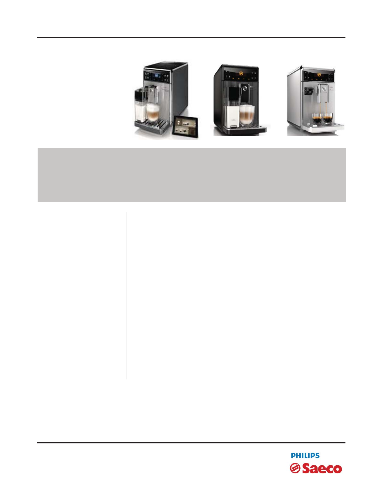
GranBaristo
GranBaristo Avanti
2013-Sept.-02
Service
Service
Manual
Manual
Rev. 02 July 2014
TECHNICAL INFORMATION
Power supply and output: 240 V~ 50 Hz 1900W - 230 V~ 50/60 Hz 1900 W 120 V~ 60 Hz 1300 W
Temperature monitoring: (NTC) variable resistor sensor - transmits the value to the electronic card
Safety system: 2 thermostats at 190°C one shot
Co ee heat exchanger output: Stainless steel
for co ee, hot water and steam dispensing
(230 V~) 1900 W - (120 V~) 1300 W - (100 V~) 1100 W
Dimensions: W x H x D in mm: 210 x 360 x 460 mm
Stand-by power consumption < 0,5W
Weight: 13 kg
Water tank capacity: 1.7 l
Co ee bean hopper capacity: 270 g. of co ee beans
Dreg drawer capacity: 20
Heating time: Approx. 45 sec.
Water circuit lling time: Approx. 15 sec Max. on rst lling cycle
Power consumption: During heating phase- approx. 5.6 A
Automatic dosage: Dose adjustment controlled by the electronic system
Material
Housing ABS/ABS+PMMA/METAL
Beans container ABS
Water tank SAN
Dreg drawer ABS
Page 2
GRAN BARISTO
MODIFICATIONS TO SERVICE MANUAL
From Rev. To Rev. Chapter Inserted Modi ed
REV.00 REV.01
02 Par.2.4 How to check for oil leaka-
ge in piston assembly.
05 Par. 5.1.1. Test Mode Granbaristo
REV.01 REV.02
01 Par. 1.6.1.
External machine parts
Par. 1.6.2.Internal machine parts
02 Par. 2.1. Technical speci cations
03 Par. 3.1.1 Customer menu in the
GranBaristo Avanti
05 Par. 5.1.1. Test Mode in GranBa-
risto Avanti
07 Par. 7.14 Bluetooth board in Gran-
Baristo Avanti
Table of contents Page
6. Standard checks
6.1. Repair schedule 1
6.2. Service schedule 1
6.3. Final test 2
7. Disassembly
7.1. Outer Shell 1
7.2. Service door 2
7.3. Co ee grinder 3
7.4. Grinder blades 3
7.5. Co ee grinder adjustment 4
7.6. Solenoid valve and assembly drain valve 4
7.7 e piston assembly 5
7.8. Pin boiler 5
7.9. Termostat 5
7.10. Pump 6
7.11. Flow-meter 6
7.12. Gearmotor and Microswtch present BrewUnit 6
7.13. CPU board and KYB interface and display
8
7.14 Bluetooth board in GranBaristo Avanti
9
7.15.
Fitting and removing Oetiker clamps
9
8. Notes
9. Water circuit diagram
10. Electrical diagram
Table of contents Page
1. Introduction
1.1. Documentation required 1
1.2. Tools and equipment required 1
1.3. Material 1
1.4. Safety warnings 1
1.5 Service Policy 2
1.6.1. External machine parts 3
1.6.2. Internal machine parts 4
2. Technical speci cations
2.1. Technical speci cations 1
2.2.1. Speci cation for the measurement of the co ee products
temperature
2
2.2.2. Speci cation for the measurement of the Milk products
temperature.
3
2.3. Machine parameters and performance 5
2.4. How to Check for oil leakage in piston assembly. 6
3. User instructions
3.1.1. Customer menu in the GranBaristo Avanti 1
3.1.2. Customer menu in the GranBaristo 4
3.2 Operation, cleaning and maintenance 5
4. Operating logic
4.1.1. Water circuit GranBaristo 1
4.1.2. Milk carafe 2
4.2. Co ee cycle 3
4.3. Single microswitch 4
4.4. Temperature sensor 4
4.5. Co ee grinder 5
4.6. Water level detection (water tank) 5
4.7. Descaling request 6
4.8. Water lter 6
5. Troubleshooting
5.1.1. Test Mode in GranBaristo Avanti 1
5.1.2. Test Mode in GranBaristo 8
5.1.2. Disagnostic Mode in GranBaristo/GranBaristo Avanti 14
5.2. Error codes 18
Page 3

GRAN BARISTO
CHAPTER 1
INTRODUCTION
Page 4
GRAN BARISTO 01 INTRODUCTION
Page / 04
1.1 Documentation required
The following documentation is needed for repair procedures:
• Instruction booklet for specifi c model
• Technical documentation for specifi c model (diagrams, exploded view, sympton cure and
service manual)
1.2 Tools and equipment required
As well as the standard equipment, the following is required:
Qty. Description Notes
1 Screwdriver
1 Pliers for Oetiker clamps
1 CC -A - Vdc tester
1 Digital thermometer Scale limit > 150°C
1 SSC (Saeco Service Center) Programmer
(for programming and diagnostics mode)
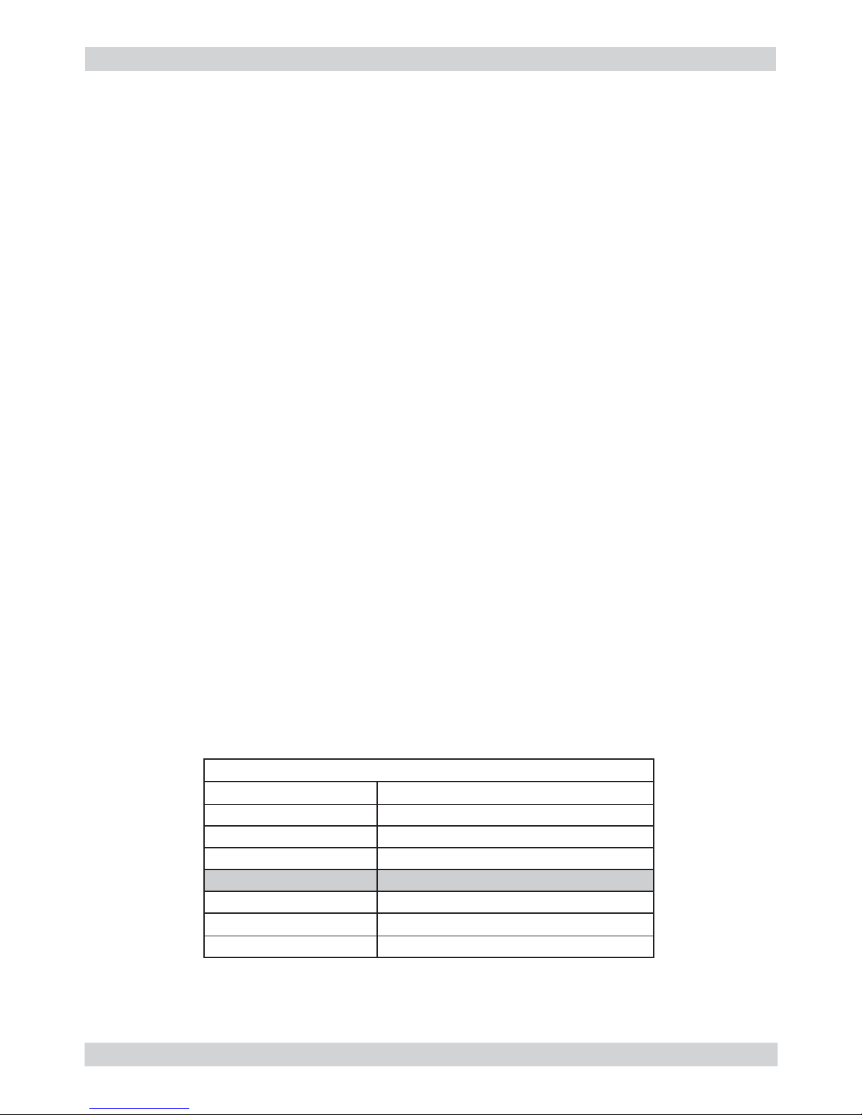
1.3 Material
Description Notes
Thermal paste Heating element > 200°C
Descaler Saeco descaler
Grease solvent Personal choice
Silicone grease Safe to use with food
1.4 Safety warnings
We recommend you consult the technical manual of the machine before performing any maintenance work.
Observe all applicable standards relating to the repair of electrical appliances.
Always disconnect the power plug from the mains before beginning repair work.
Simply turning off the main machine power switch is not an adequate safety precaution.
This domestic appliance is rated as insulation class I.
On completion of the repair work, insulation and dielectric rigidity tests must be performed.
01
Page 5
GRAN BARISTO 01 INTRODUCTION
Page / 04
02
1.5 Service POLICY grid as used for coffee machine
Components Assembly use Single components available
COFFEE
GRINDER
Only for OOW repairs
YES, to consult the specifi c exploded-view of the
machine or of the Coffee Grinder on website
BREWING
UNIT
Only for OOW repairs
YES, to consult the specifi c exploded-view of the
machine or of the Brewing unit on website
PISTON UNIT
ASSY.
Only for OOW repairs
YES, to consult the specifi c exploded-view of the
machine on website
GEAR
MOTOR
Only for OOW repairs
YES, to consult the specifi c exploded-view of the
machine on website
FILTER
HOLDER
Only for OOW repairs
YES, to consult the specifi c exploded-view of the
machine on website
MILK
CARAFE
Only for OOW repairs
YES, to consult the specifi c exploded-view of the
machine on website
List of principal assembly present in all our coffee machines
For IN WARRANTY repairs is mandatory to use the single components (not the assembly) avail-
able in the exploded views of the coffee machines or of the specifi c components. If you fi nd the
information “SEE THE EXPLODED VIEW E........” in the assembly description fi eld, it means that
the single components of the assembly are available in the other pages of the exploded view. It’s
possible to use the assembly only if there is a specifi c Symptom Cure that include this possibility
or when the single components are not available for the order.
Page 6
GRAN BARISTO 01 INTRODUCTION
Page / 04
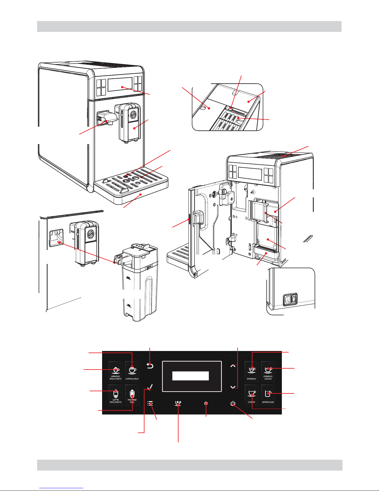
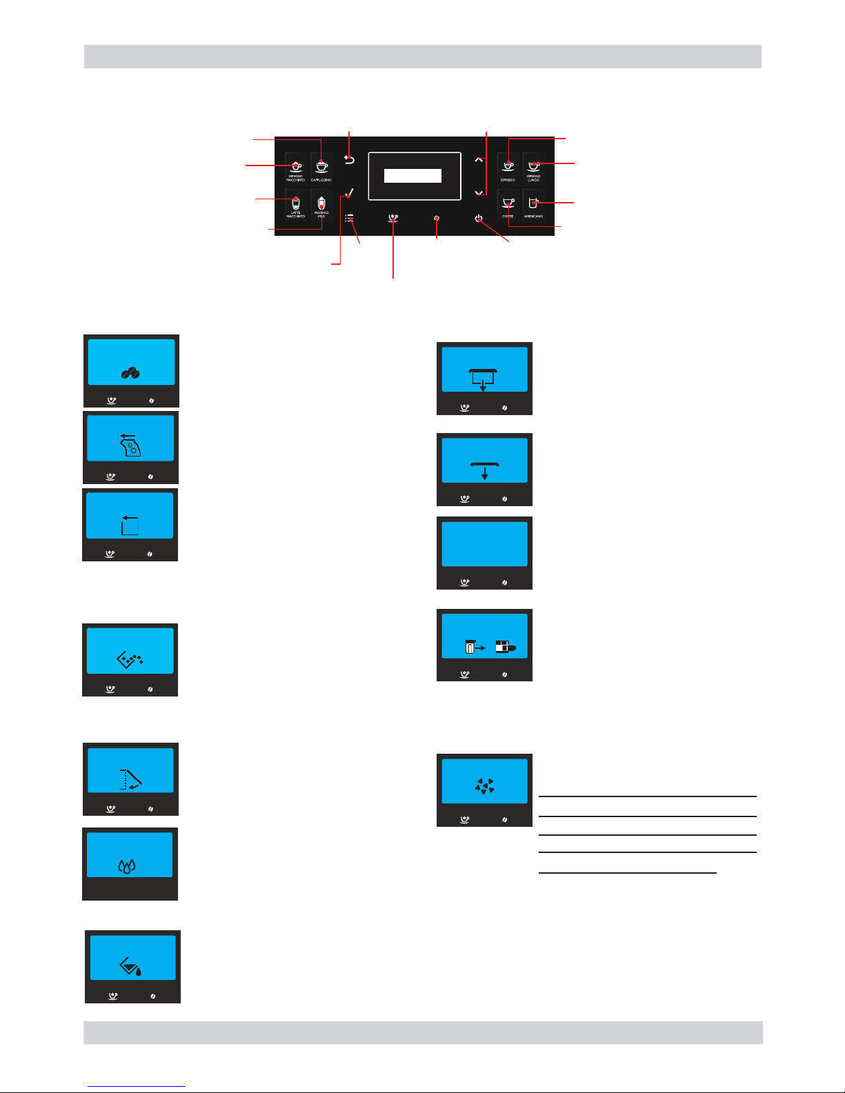
1.6.1 External machine parts
Pre-ground coffee
compartment
Coffee bean hopper locking/removal
selector switch (depending on the model)
Removable coffee bean
hopper lid (depending
on the model)
Water tank + lid
Power cable socket
and main switch
Milk carafe
attachment
Milk carafe
Cup holder
grille
Full drip tray indicator
Drip tray
(internal)
Removable
dispenser
spout
Control
panel
Hot water
dispensing spout
Drip tray
(internal)
Service
door
Coffee grounds
drawer
Brew group
locking/removal
selector
Brewing group
Service door
button
Cup-warming
surface
03
Gran Baristo Avanti
“Espresso”
button
“Long Espresso ”
button
“Coffee”
button
“Aroma”
Pre-ground
coffee button
“Espresso Macchiato”
button
“Cappuccino”
button
“Latte Macchiato”
button
“Hot Milk”
button
“ESC”
button
“OK”
button
“MENU”
button
“Special Beverages”
button
“Stand-by”
button
“UP” and ”DOWN “
button
LCD Display
“American Coffee”
button
Page 7
GRAN BARISTO 01 INTRODUCTION
Page / 04
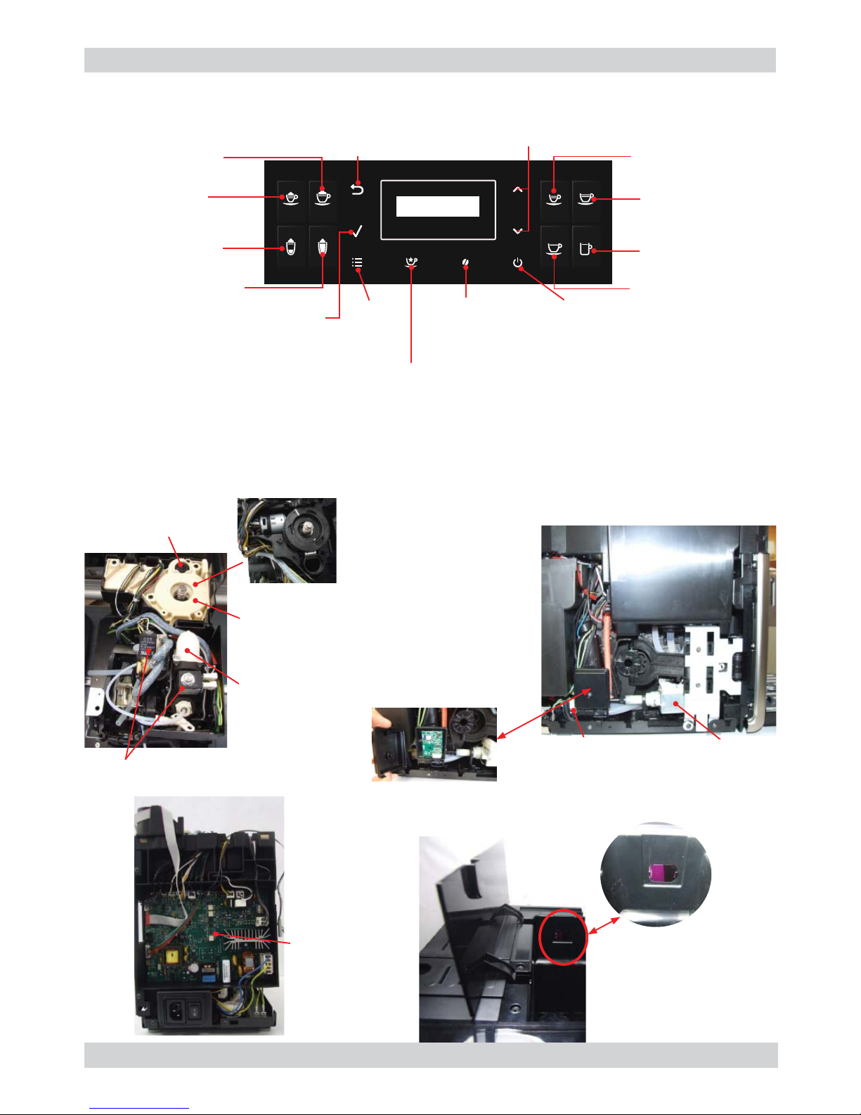
“Espresso”
button
“Coffee”
button
“American Coffee”
button
“Cafè Crème”
button
“Aroma”
Pre-ground
coffee button
“Espresso Macchiato”
button
“Cappuccino”
button
“Latte Macchiato”
button
“Hot Milk”
button
“ESC”
button
“OK”
button
“MENU”
button
“Special Beverages”
button
“Stand-by”
button
“UP” and ”DOWN “
button
LCD Display
1.6.2 Internal machine parts
04
Power board
IRDA
(To program the machine)
Bluetooth board in
Granbaristo Avanti
Solenoid valve
Grinding
adjustment insert
Cover and
Coffee grinder
Coffee grinder
Piston assembly
Gran Baristo
Pump
Flow-meter
Page 8

GRAN BARISTO
CHAPTER 2
TECHNICAL
SPECIFICATIONS
Page 9
GRAN BARISTO 02 TECHNICAL SPECIFICATIONS
Page / 06
2.1. Technical specifi cations
Power supply and output:
240 V~ 50 Hz 1900W - 230 V~ 50/60 Hz 1900 W
120 V~ 60 Hz 1300 W
Temperature monitoring:
(NTC) variable resistor sensor - transmits the value to the
electronic card
Safety system:
2 thermostats at 190°C one shot
Coffee heat exchanger output:
Stainless steel for coffee, hot water
and steam dispensing
(230 V~) 1900 W - (120 V~) 1300 W - (100 V~) 1100 W
Gear motor: 2 rotation directions; power supply 24VC
Pump:
Ulka Type EP5/S GW approx. 13-15 bar with reciprocating
piston and thermal switch 100°C 48 W, 230V, 50 Hz, 120V,
60Hz 100V, 50/60 Hz
Overpressure valve: Opening at approx. 16-18 bar
Water fi lter: In tank
Coffee grinder: Direct current motor with fl at ceramic grinder blades
Automatic dosage: Dose adjustment controlled by the electronic system
Power consumption: During heating phase- approx. 5.6 A
Dimensions: W x H x D in mm: 210 x 360 x 460 mm
Weight: 13 kg
Water tank capacity: 1.7 l
Coffee bean hopper capacity: 270 g. of coffee beans
Dreg drawer capacity: 20
Water circuit fi lling time: Approx. 15 sec Max. on fi rst fi lling cycle
Heating time: Approx. 45 sec.
Grinding time: Approx. 8-10 sec.
Only Gran Baristo Avanti
Bluetooth: Bluetooth Smart (low energy)
Maximum use distance: 5 m
Tablet compatibility:
Avanti App is compatible with iPad 3/4/Air/mini retina,
running iOS7 and newer; with Samsung Galaxy
Tab 3 (8.0’’)/Tab 4 (10.1’’)/Note pro LTE (12.2’’), Nexus 7
2013 (7’’), Sony Xperia Z LTE (10.1’’), running
Android v.4.3 and newer, and Bluetooth version 4.0 and
newer.
01
Page 10
GRAN BARISTO 02 TECHNICAL SPECIFICATIONS
Page / 06
02
2.2.1. Specifi cation for the measurement of the coffee products temperature.
The temperature is infl uenced by the fl ow from the dispenser and stratifi cation of temperatures in
the glass. In order to consider these phenomena and to introduce measures that allow comparisons in controlled conditions, below guidelines must be followed:
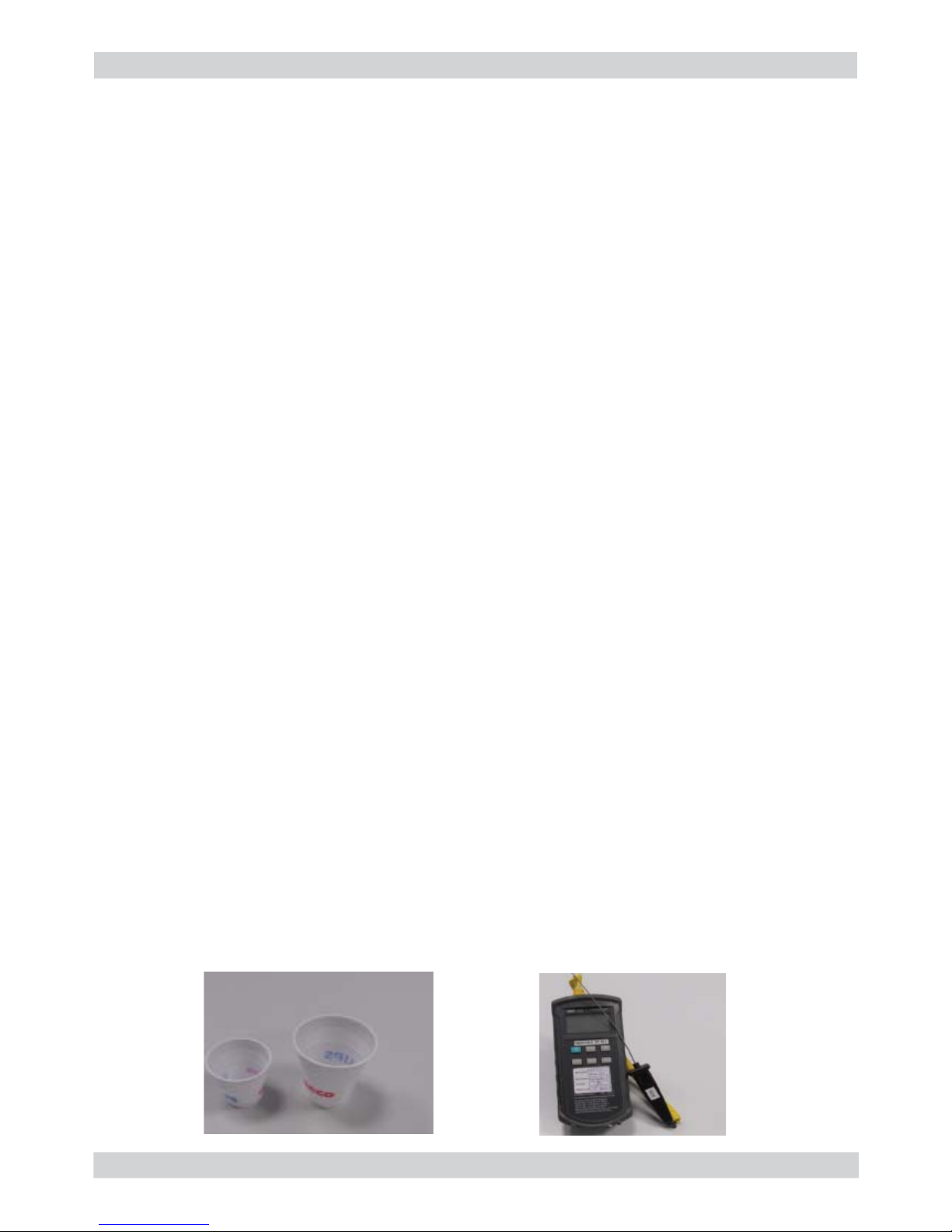
Conditions:
a) Water temperature in tank: 23°C (+/-2°C).
b) It must be used a plastic cup (see picture N°1).
c) It must be used a thermocouple thermometer (e.g. type K - see picture N°2).
d) The coffee machine is tested without any change of parameters or calibrations, which may
affect the temperature of products, so the measurement of temperature must be done with
machine in default factory setting.
Procedure:
1. The temperature must be measured in the cup, immediately after dispensing. Cup has to be
placed on a non-metal surface using a thermocouple thermometer.
2. The temperature in the cup is measured by immersing the probe of the thermometer up to
touch the bottom.The probe then must be moved in a circular motion for 5/6 rotations. At the
of the rotations, stop in the center of the cup.
3. The highest temperature measured during the rotations is the value we are searching for, and
that must be reported;
4. Test measurement: from end of dispensing to the end of rotations must be completed within 12
seconds.
Limits of acceptability
The acceptance limits are divided by features and products and are the following:
Espresso Coffee Italy Q.ty 25/40 gr.
Temperature of 1st product 69°C ≤ 85°C
Temperature of 2nd product 72°C ≤ 85°C
Coffee Q.ty 70/120 gr.
Temperature of 1st product 69°C ≤ 85°C
Temperature of 2nd product 72°C ≤ 85°C
Picture 1
Picture 2
Page 11
GRAN BARISTO 02 TECHNICAL SPECIFICATIONS
Page / 06
03
2.2.2. Specifi cation for the measurement of the Milk products temperature.
Milk evaluation
To carry out the test, a partially skimmed UHT milk with a percentage of grease between 1.5-
1.8% at a refrigerator temperature Trefr. (between 4 to 10°C) must be used.
The milk product must be checked on a beaker of 250 ml of capability and with an inner diameter
of 70mm, brewing 100gr of product.
Parameters to be respected:
The parameters to be respected are: milk temperature and height of the cream. Each of these
parameters, however, must be evaluated depending on the type of system used for the production
of hot milk.
Actually three types of devices are present on the appliances:
- Manual system (pannarello)
- Semi-Automatic system (cappuccinatore)
- Automatic system (carafe, Pinless wonder system, etc.)
Milk temperature in the beaker:
System without Pinless Wonder: e.g. Xelsis, Exprelia, Syntia, Intelia.
With milk at Trefr. (about 4-10 °C): ≥ 36
System with Pinless Wonder: New royal, Energica Pure, Intelia EVO Latte.
With milk at Trefr. (about 4-10 °C): ≥ 45
Height of the milk cream in the beaker:
Manual system (pannarello)
≥ 15mm on 100gr. of brewed product
Semi-automatic system (cappuccinatore)
≥ 20mm on 100gr. of brewed product
Automatic system: carafe, cappuccinatore, Pinless wonder (New Royal, Energica Pure, Intelia EVO
latte)
≥ 20mm on 100gr. of brewed product
How to measure the temperature of the milk.
1) The measurement is carried out in the beaker, immediately after the end of milk brew,
positioned on a non-metallic surface, using a thermocouple thermometer (eg. Type K).
Stop the preparation of mixed product: at the end of milk brewing, where
“One Touch product” function is present.
2) The temperature is measured by immersing the probe of the thermometer, positioning the
probe inside the beaker at about 10mm from the bottom of the container, then the probe
moves in a circular motion for 3-5 turns, stopping at the end, at the center of the beaker.
It detects the maximum temperature reached in a time of relief between 3 to 5 seconds. It
is important the mixing of milk before the measurement at 10mm from the bottom of the
beaker. If the mixing is correct, temperature, for a few fractions of a second, during the
measurement should not oscillate.
Page 12
GRAN BARISTO 02 TECHNICAL SPECIFICATIONS
Page / 06
How to measure the milk cream.
The temperature (Trefr or Tamb) of the milk doesn’t affect as much the test result on measuring
the milk cream; by convection is assumed to always use milk at refrigerator temperature Trefr.
Manual systems (Pannarello)
Pour 100cc. of milk at Trefr. in a beaker of 250 ml of capacity and with a inner diameter of 70 mm;
with machine in steam mode:
1. Open the steam knob to discharger water circuit for 4 sec, then close the knob.
2. Place the beaker with the frother dipped in milk, open the steam knob to maximum and
start the chronometer.
3. After about 30 to 60 seconds, close the knob and check the result on milk.
Semi-automatic systems (cappuccino)
Pours milk at Trefr. in a container ; with the machine in steam mode:
1. Open the steam knob to discharge water circuit for 4 sec. then close the knob.
2. Insert the silicone tube in the milk container, placing a beaker of 250 ml capacity and with
an inner diameter of 70 mm under the cappuccino maker and open the steam knob.
3. After having provided 100gr. of product, close the knob and check the result obtained on
milk. Note: The same applies to machines which have a steam key on the user interface
and a solenoid valve in place of the steam tap.
Automatic: Carafe, Cappuccino Pinless wonder (New Royal, Energica Pure, Intelia EVO
Latte), etc..
After setting the machine to delivery of 100gr. of product:
1. Launch the “hot milk” function.
2. Collect the product in a beaker with a 250ml of capacity and with an inner diameter of
70 mm, and verify the result obtained on milk. Carry out the test using milk at a Trefr..
In case the machine allows modify of the emulsion through the menu, use the machine with the
emulsion set to the default value.
Related to the above testing procedure derives the following table of acceptability:
Manual, Semi-Automatic and Automatic’s Milk System
Grams of Product Minimun Height of the milk cream
≥ 130 ≥ 30mm
120 ≥ 25mm
110 ≥ 22mm
100 ≥ 20mm
90 ≥ 16mm
80 ≥ 13mm
70 ≥ 11mm
NB: To verify more accurately the height of the cream, a practical expedient dictated by experience is to add to the product just delivered a small amount of coffee. The addition of coffee
immediately put in evidence the surface of separation between liquid and cream.
04
Page 13
GRAN BARISTO 02 TECHNICAL SPECIFICATIONS
Page / 06
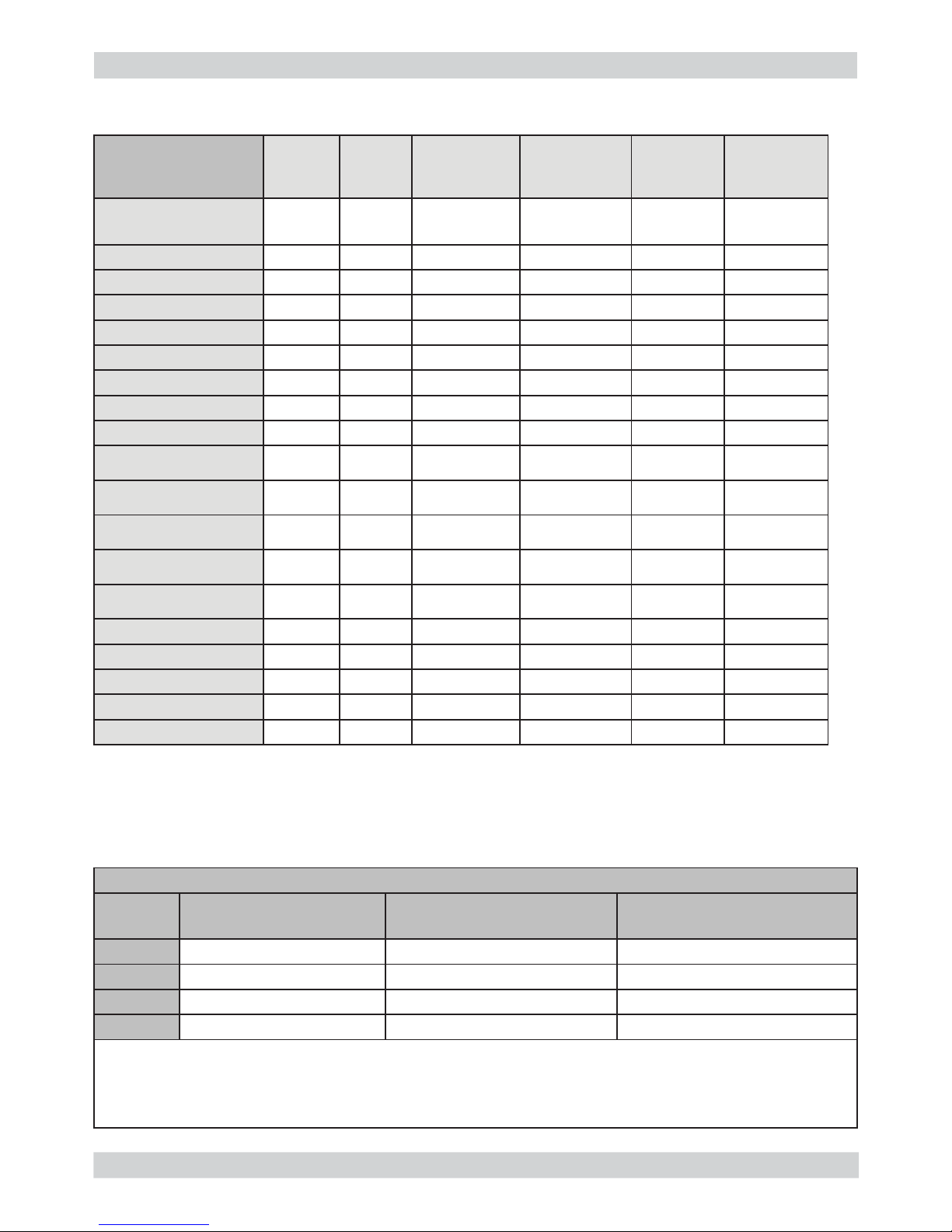
2.3. Machine parameters and performance
PRODUCT
QUANTITY
Minimum
Water
quantity
(ml)
Maximum
Water
quantity
(ml)
Default Water
quantity (ITA)
(ml)
Default Water
quantity (ENG)
(ml)
Milk Length
(sec)
Aroma
AmericanCoffee
110 320 170 170
3 = Regular
Espresso
30 70 40 50
3 = Regular
Cafe Creme
40 110 70 70
3 = Regular
Coffee
70 140 110 110
3 = Regular
Ristretto
20 40 30 30
3 = Regular
Espresso Mild
30 70 40 50
2 = Mild
Espresso Intenso
40 110 70 70
6 = Extra Strog
Energy Coffee
110 320 170 170
6 = Extra Strog
Hot Water
50 450 300 300
Latte Macchiato
30 170 70 110
Default: 25
Range: 10-75
3 = Regular
Cappuccino
30 170 40 70
Default: 20
Range: 10-50
3 = Regular
Espresso Macchiato
30 70 40 50
Default: 5
Range: 5-30
3 = Regular
Cafe au lait
30 260 70 110
Default: 20
Range: 10-50
3 = Regular
Frothed Milk
Default: 30
Range: 10-75
Startup Rinsing
100 100
Short Rinsing
40 40
Power off Rinsing
100 100
Water fi lter activation
1000 1000
Brewing Unit cleaning
800 800
05
Descaling cycle frequency
Hard-
ness
Water hardness Without water fi lter With water fi lter
1 Soft (up to 7°dH) 240 litres (480,000 pulses) 480 litres (960,000 pulses)
2 Medium (7° - 14°dH) 120 litres (240,000 pulses) 240 litres (480,000 pulses)
3 Hard (15° - 21°dH) 60 litres (120,000 pulses) 120 litres (240,000 pulses)
4 Very hard (over 21°dH) 30 litres (60,000 pulses) 60 litres (120,000 pulses)
The default water hardness level is 4. Each litre of water corresponds to approximately
2,000 pulses.
In the machines where is not possible change the water hardness the default hardness level is 3.
Page 14
GRAN BARISTO 02 TECHNICAL SPECIFICATIONS
Page / 06
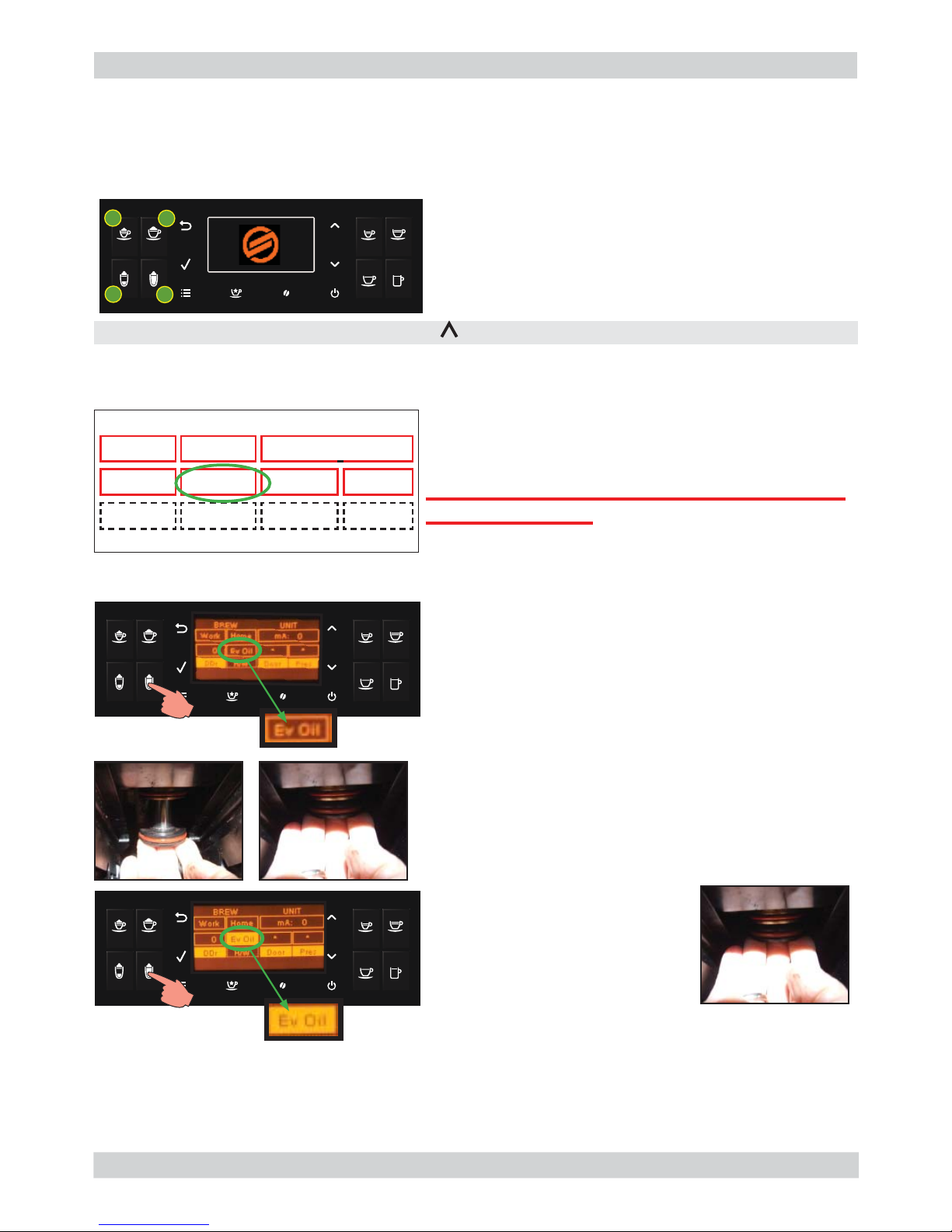
In case of return because the machine indicates no coffee one of the causes could be the loss of oil from the piston assembly.
To check this, proceed as follows:
To enter Test Mode
When the display is turning ON, press the keyboard buttons in the order described below:
4
3
2
1
Brew Unit
This page allows to test the functionality of Brew Unit, BU Encoder, frontal door and dreg drawer:
EV activate
The piston moves upward until it stops.
WARNING: Deactivate the EV only when
it goes back into its original position. Failing
to do so could result in air being sucked into
the circuit.
In case of oil leakage, remove the piston assembly clean any oil residue with a dry cloth and replace the piston assembly with a
new one.
NOTE: Oil is of vegetal origin, certifi ed for food contact, H3 (maximum in terms of food safety for oils).
EV deactivate
The piston moves upward of approx. 5mm (OK)
ERROR: excursion >5mm approx. is (KO)
The meaning of the sectors are the following:
Command:
Work: when pressed moves the brew unit to WORK
Home: when pressed moves the brew unit to HOME
Ev Oil: when pressed activates/deactivates the Oil
electrovalve (24V Dc)
Rst: when pressed moves the brew unit in
RESET(extraction) position(stop the brew unit if was in
movement)
Press UP ( ): go to next page
OK
OK
KO
The piston moves up in case of lack of oil
BREW UNIT
Work Home mA: 0
0 Ev Oil Rst 4000
DDr H/W Door Pres
2.4. How to Check for oil leakage in piston assembly.
06
Page 15

GRAN BARISTO
CHAPTER 3
USER INSTRUCTIONS
Page 16
GRAN BARISTO 03 USER INSTRUCTIONS
Page / 05
3.1.1. Customer menu in the Gran Baristo Avanti
01
Display messages
“Espresso”
button
“Long Espresso ”
button
“Coffee”
button
“Aroma”
Pre-ground
coffee button
“Espresso Macchiato”
button
“Cappuccino”
button
“Latte Macchiato”
button
“Hot Milk”
button
“ESC”
button
“OK”
button
“MENU”
button
“Special Beverages”
button
“Stand-by”
button
“UP” and ”DOWN “
button
LCD Display
“American Coffee”
button
BEANS CONTAINER EMPTY
ADD COFFEE BEANS
INSERT BREW GROUP
INSERT COFFEE
GROUNDS DRAWER
CLOSE
FRONT DOOR
CLOSE BEAN
CONTAINER LID
HOT WATER
INSERT
WATER SPOUT
PLACE MILK CARAFE
AND OPEN SPOUT
EMPTY COFFEE
GROUNDS DRAWER
WATER TANK EMPTY
ADD WATER
EMPTY INTERNAL
DRIP TRAY
INSERT
BEAN CONTAINER
DESCALE
Fill the coffee bean hopper.
Insert the coffee bean hopper
and/or beans lid.
Insert the coffee bean hopper
lid and/or beans lid.
Insert the water dispensing
spout to start dispensing. Press
“ESC” to exit.
Before dispensing, insert the
milk carafe with the dispensing
spout open.
The brew group must be inserted
into the machine.
Insert the coffee grounds drawer
and the internal drip tray.
Close the service door.
Remove the water tank and fi ll it.
You can fi ll the water tank also
through the dedicated hole on the
lid.
Empty the coffee grounds drawer.
Note: The coffee grounds drawer
must be emptied only when the
machine requires it and with
the machine on. If the drawer is
emptied with themachine turned
off, the machine will not record the
emptying operation.
Open the service door and empty the internal drip tray.
Note:If this operation is performed when the machine is on, it will record the
coffee grounds drawer emptying and will reset the counter; therefore,
you need to empty the coff ee grounds as well.
You need to descale the machine. Follow the steps described
in the “Descaling” chapter of
this manual.
Please note that not descaling
your machine will ultimately
make it stop working properly.
In this case repair is NOT covered under your warranty.
Page 17
GRAN BARISTO 03 USER INSTRUCTIONS
Page / 05
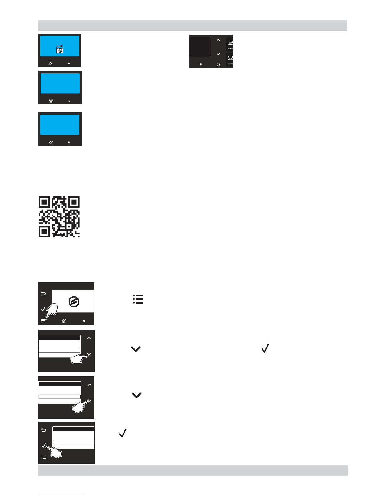
02
WATER CIRCUIT
PRIMING
RESTART TO SOLVE
CHANGE FILTER
The machine needs the
“INTENZA+” water fi lter to be
replaced.
The machine is priming the
water circuit. Wait for this
operation to be over.
Download the application on your mobile device to access the machine functions.
To connect GranBaristo Avanti with your mobile device, download the Saeco
Avanti App available on the App Store and Google Play or scan the QR code
on the cover with your mobile device. As an alternative, connect to the www.
saeco.com/Avanti-app website using the device on which you wish to download
the application.
The GranBaristo Avanti Bluetooth function is enabled by default. If it is disabled, follow the instructions below to enable it again:
Note:
Before starting the connection procedure, make sure that the Bluetooth
function on your mobile device is active.
The red light fl ashes. Press any
button to exit the stand-by mode.
Take note of the code (E xx) shown on the display at the bottom.
Turn off the machine. Turn it back on after 30 seconds. Repeat the procedure 2 or
3 times.
If the machine does not start, contact the Philips SAECO hotline in your country
and quote the code shown on the display. Contact details can be found in the warranty booklet packed separately or at www.philips.com/support.
BLUETOOTH CONNECTION
PROFILE SAECO
MENU
EDIT PROFILES
MAINTENANCE
SETTINGS
STATISTICS
SETTINGS
STAND-BY TIME
BUTTON SOUND
BLUETOOTH
RESTORE TO DEFAULT
SETTINGS
STAND-BY TIME
BUTTON SOUND
BLUETOOTH
RESTORE TO DEFAULT
Press the “ ” button to access the machine main menu.
Press the “ ” button to select “SETTINGS”. Press “ ” to confi rm.
Press the “ ” button to select “BLUETOOTH”.
Press “ ” to confi rm.
Page 18
GRAN BARISTO 03 USER INSTRUCTIONS
Page / 05
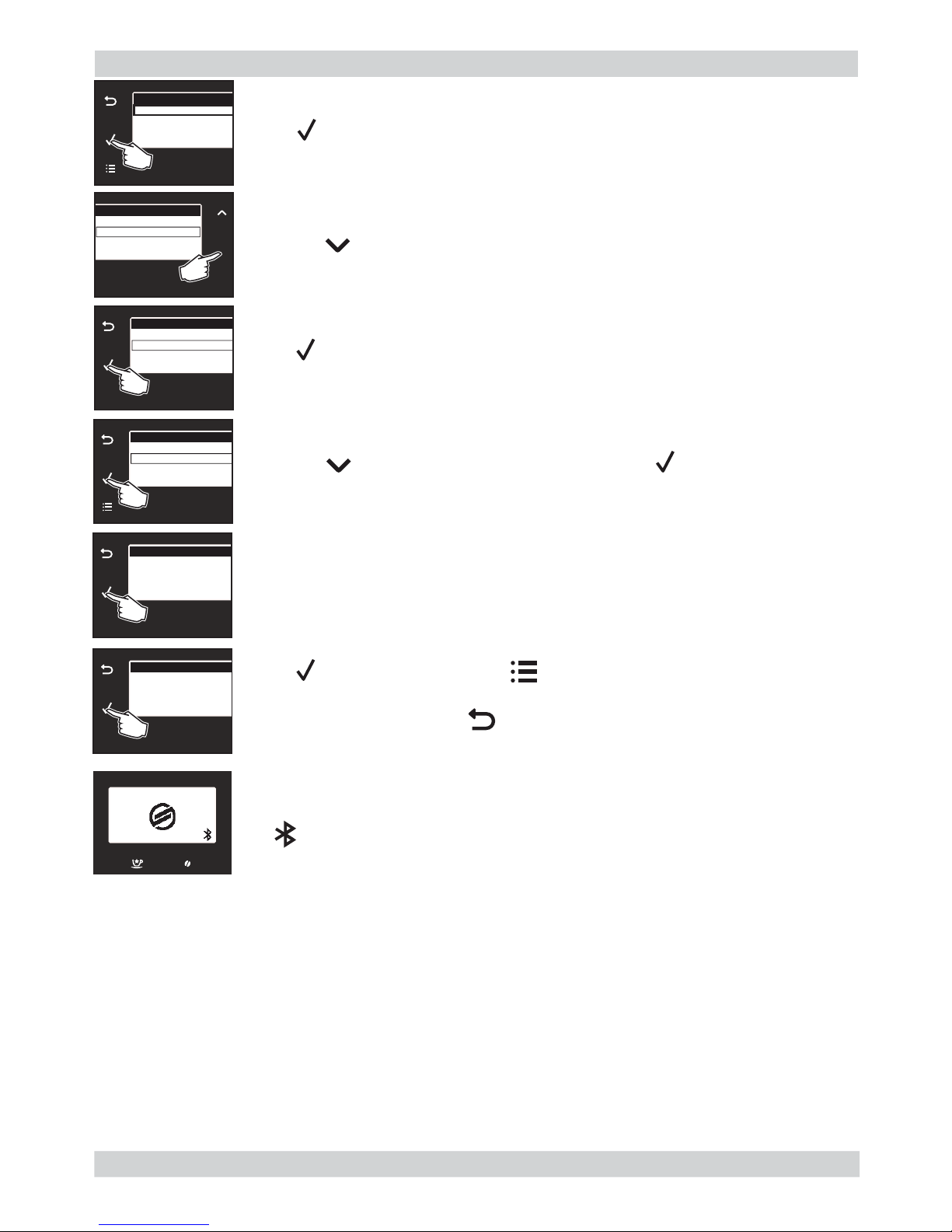
BLUETOOTH
ENABLE BLUETOOTH
PIN CODE
ADDRESS
ENABLE BLUETOOTH
OFF
ON
ENABLE BLUETOOTH
OFF
ON
BLUETOOTH
ENABLE BLUETOOTH
PIN CODE
ADDRESS
Note:
To exit the menu, press the “ ” button.
Press “ ” to confi rm. The Bluetooth device is now active.
Write down the code, as it will be requested when connecting with your mobile
device.
Press “ ” to confi rm. Press the “ ” button to exit.
PIN CODE
6982
PIN CODE
6982
PROFILE SAECO
Enter the PIN code when you are prompted by the application and wait
for a successful connection.
The icon shown on the display indicates that the connection was
successfully established. Now you can interact with your coffee machine
directly from your mobile device.
Warning:
Use the Saeco Avanti app to control your Gran Baristo only when you can see the machine in order to avoid injury or damage! You cannot use the pre-ground coffee function when operating the
machine via the app.
Caution:
If you enter the wrong PIN code 5 times in a row, the machine disables the Bluetooth connection
for safety reasons. Therefore, you will need to enable it again as previously explained.
Note:
Avanti App is compatible with iPad 3/4/Air/mini retina, running iOS7 and newer; with Samsung
Galaxy Tab 3 (8.0’’)/Tab 4 (10.1’’)/Note pro LTE (12.2’’), Nexus 7 2013 (7’’), Sony Xperia Z LTE
(10.1’’), running Android v.4.3 and newer, and Bluetooth version 4.0 and newer.
Press the “ ” button to select “PIN CODE”. Press “ ” to confi rm.
Press the “ ” button to select “ON”.
The “BLUETOOTH” management menu is displayed.
Press “ ” to enable the function in the machine and to allow the connection
of your mobile device.
03
Page 19
GRAN BARISTO 03 USER INSTRUCTIONS
Page / 05
3.1.2. Customer menu in the Gran Baristo.
Display messages
“Espresso”
button
“Coffee”
button
“American Coffee”
button
“Cafè Crème”
button
“Aroma”
Pre-ground
coffee button
“Espresso Macchiato”
button
“Cappuccino”
button
“Latte Macchiato”
button
“Hot Milk”
button
“ESC”
button
“OK”
button
“MENU”
button
“Special Beverages”
button
“Stand-by”
button
“UP” and ”DOWN “
button
LCD Display
ADD COFFEE
Fill the coffee bean hopper.
Insert the coffee bean hopper
and/or beans lid.
Insert the water dispensing spout
to start dispensing. Press “ESC” to
exit.
Before beginning to dispense,
insert the milk carafe with the dispensing spout open.
The brew group must be inserted
into the machine.
Insert the coffee grounds drawer
and the internal drip tray.
Close the service door.
Remove the water tank and fi ll it.
You can fi ll the water tank also
through the dedicated hole on the
lid.
The machine needs the
“INTENZA+” water fi lter to be
replaced.
The red light fl ashes. Press any
button to exit the stand-by mode.
Take note of the code (E xx) shown on the display at the bottom and check out the
table “Error codes” (par.05 TROUBLESHOOTING) the type of error that occurred.
Open the service door and empty the internal drip tray.
Note: If this operation is performed when the machine is on, it will record the coffee
grounds drawer emptying and will reset the counter; therefore, it is necessary to empty the coffee grounds as well.
Empty the coffee grounds drawer.
Note: The coffee grounds drawer
must be emptied only when the
machine requires it and with
the machine on. If the drawer is
emptied with themachine turned
off, the machine will not record the
emptying operation.
INSERT BREW GROUP
INSERT COFFEE
GROUNDS DRAWER
EMPTY COFFEE
GROUNDS DRAWER
CLOSE
FRONT DOOR
REFILL
WATER T ANK
EMPTY DRIP TRAY
INSERT
BEAN CONTAINER
HOT WATER
INSERT
WATER SPOUT
CAPPUCCINO
INSERT THE CARAFE
WITH THE SPOUT
OPEN
RESTART TO SOLVE
The machine needs to be descaled.
Follow the steps described in the
“Descaling” chapter of this manual.
Please note that not descaling your
machine will ultimately make it stop
working properly. In this case repair
is NOT covered under your warranty.
04
Page 20
GRAN BARISTO 03 USER INSTRUCTIONS
Page / 05
CLEANING AND TECHNICAL SERVICING
A Empty the dregs drawer When indicated
B Empty the drip tray As necessary
C Clean the water tank Weekly
D Clean the coffee bean hopper As necessary
E Clean the casing As necessary
F
Clean the brewing unit Every time the coffee bean hopper is fi lled or weekly
Lubricate the brewing unit After 500 dispensing cycles or when the grease is no
longer present on the brewing unit
Clean the unit housing Weekly
H Descaling When indicated
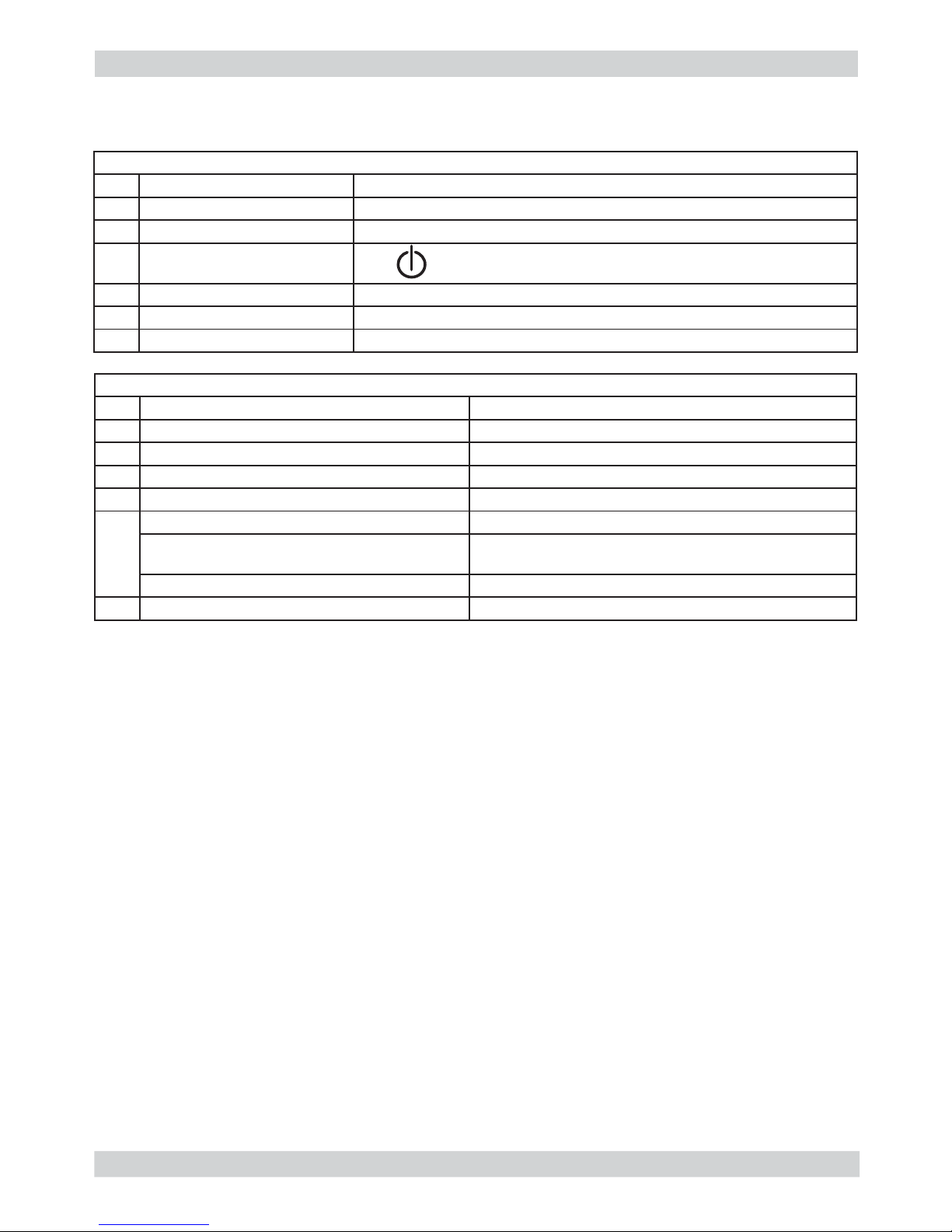
3.2. Operation, cleaning and maintenance
Operating the machine
1 Fill water tank
2 Fill the coffee bean hopper
3 Switch on the appliance
4
Press the button to start the
appliance
5 Heating When the heating phase begins, wait for it to fi nish
6 Rinse Carry out a rinse cycle for the internal circuits
7 Machine ready The machine is ready to dispense beverages
05
Page 21

GRAN BARISTO
CHAPTER 4
OPERATING LOGIC
Page 22

GRAN BARISTO 04 OPERATING LOGIC
Page / 06
01
Steam
Compensation valve water outlet
Flow-meter
Boiler
Water
Hot water /steam
Compensation valve water outlet
Pump
Brewing unit
4.1.1. Water circuit Granbaristo
Water tank
Page 23

GRAN BARISTO 04 OPERATING LOGIC
Page / 06
02
4.1.2. Milk Carafe
1) Steam input
2)Bring the cappuccino maker into
dispensing position
3) Milk tank
1
2
The milk is heated by the
steam and taken towards
the emulsion chamber
where it is mixed with
air and transformed into
foam
The steam passes
through the pipe creating
a sucking effect that pulls
the milk upwards
Page 24

GRAN BARISTO 04 OPERATING LOGIC
Page / 06
Notes: * Only with Pre-brewing
4.2. Coffee cycle
Switching on
When the machine is switched on, the gear motor repositions itself as follows:
- It acts on microswitch 1 (see following chapter).
- The gear motor changes its rotation direction and moves upwards again by approx. 1-2 mm.
- The boiler begins to heat the water for approx. 30 sec with controlled power, in order to reach
the optimal temperature. The temperature will then remain at a constant level.
Coffee cycle
1. The grinding process is controlled by time duration in function of coffee strength selected.
2. The gear motor (brewing unit) moves to the brewing position.
3. Preliminary dispensing phase (short pump activity, short pause).
4. Product dispensing (the pump operation period is defi ned by the amount of product dis-
pensed).
5. The gear motor moves to its home position (the dregs are expelled automatically).
Main switch ON START STOP
Time
Coffee grinder
Heating
Pump
Brewing unit gear
motor
Status Heating Ready Coffee cycle
Pulses
(Dosage)
Pump operation (fl ow
meter pulses) in
accordance with the
amount of product
selected.
approx.
45 sec.
*
03
Single microswitch gear motor
Status
Microswitch
OFF
ON
Page 25

GRAN BARISTO 04 OPERATING LOGIC
Page / 06
An NTC is used as a temperature sensor; in the event of overheating this reduces boiler element
power consumption.
The electronic system detects the current boiler temperature from the drop in voltage of the
sensor and adjusts it accordingly.
Heating element values and corresponding temperatures: see table.
4.4. Temperature sensor (adjustment)
Temp. (°C) R nom (kΩ) ΔR (+/- %)
20 61.465 8.6
50 17.599 5.9
75 7.214 4.1
80 6.121 3.7
85 5.213 3.4
90 4.459 3.1
100 3.3 2.5
125 1.653 3.9
150 0.893 5.1
4.3. Single microswitch
The gear motor is powered by a direct
current motor that engages with the
smaller double toothed wheel using a
worm screw. The unit is mounted on the
axle of the large gear wheel and when
a coffee is requested, it moves from the
standby position to the dispensing position, and then back to the standby position again.
- Standby position: 1
- Dispensing position: 2
04
2
1
Page 26

GRAN BARISTO 04 OPERATING LOGIC
Page / 06
4.5. Coffee grinder
The coffee grinder is driven by a direct current motor (1) using a worm screw helicoidal wheel
transmission (2).
The worm screw (2) drives a plastic gear wheel (3), which turns the lower grinder (4) and the
increment pin (5)
05
4.6. Water level detection (water tank)
“Water low” message (water reserve)
Function:
The water level is monitored by a capacitative sensor, located one
third of the way up the water tank wall.
If the electronics assembly detects, by means of the sensor,
that the amount of water in the tank has dropped below the
above mentioned level, a water reserve remains available for
the dispensing process underway (this will cover 200 fl ow meter
pulses).
The product dispensing process will then come to an end.
If a dispensing cycle ends after the sensor has been triggered (in
the reserve) then the display “Water low” continues to be displayed
during the following dispensing cycle.
200 puls.
Sensor
Water tank
2
3
4
5
1
Page 27

GRAN BARISTO 04 OPERATING LOGIC
Page / 06
06
“Descaling” – message with water fi lter
inserted
(appliances with display only)
The water hardness is set on the basis of the
regional water hardness analysis
(1, 2, 3, 4).
Filter off:
If the function is turned o the electronics
assembly monitors the fl ow meter pulses,
recording one pulse each turn.
Filter on:
If the function is turned on the electronics
assembly monitors the fl ow meter pulses,
recording one pulse every two turns.
“Change water fi lter” message
The electronics assembly uses the fl ow meter
impulses to keep track of the amount of water
which has fl owed through; after the specifi ed
amount (set in accordance with the water
hardness level), the “Replace fi lter” message
appears.
4.7. Descaling request
360°
1 rev
Number of pulses
Filter
on
Filter
off
Flow meter pulses
Bypass
4.8. Water fi lter
Function:
• Reduced limescale deposits which take longer to form.
• Improved water quality.
• Improved taste due to the ideal water hardness.
Life span / descaling performance:
• - 10 ° dH
• 60 litres
• 2 months
To achieve the best possible operating mode consistency
over the total life span, the water is channelled using
a 3-stage bypass (A, B, C) depending on the degree of
hardness. See small image.
Page 28

GRAN BARISTO
CHAPTER 5
TROUBLESHOOTING
Page 29

GRAN BARISTO 05 TROUBLESHOOTING
Page / 18
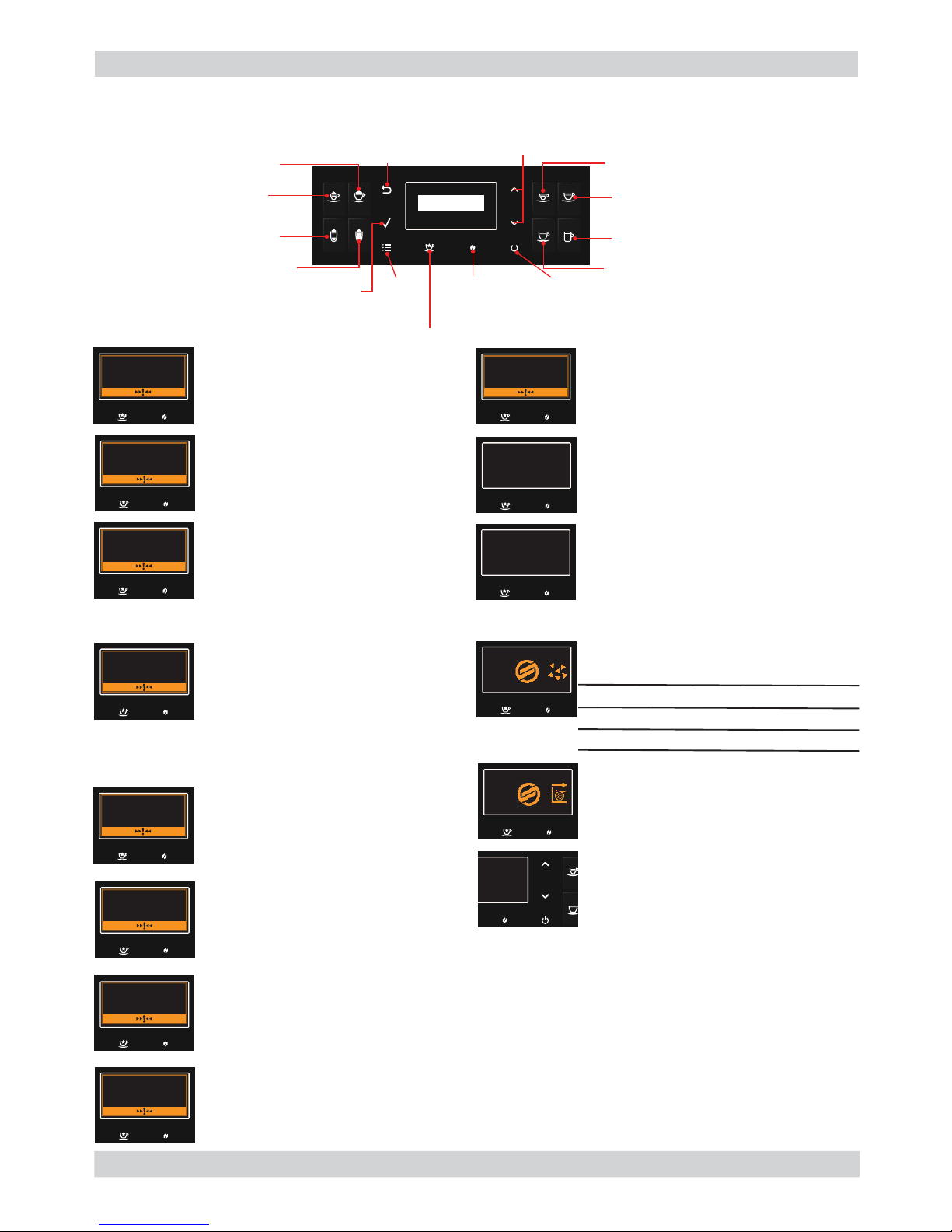
5.1.1. Test Mode Gran Baristo Avanti
4
32
1
To enter Test Mode
When the display turns ON, press the keyboard buttons in the order described below:
Description
When the machine is in Factory Test Mode appears a windows divided in several sectors:
The fi rst row of each window is a title, the red sectors represents the functions (or loads) avail-
able to activate or deactivate, the last row is used to show other info. When a function is enabled
the corresponding box becomes colored. The dotted sectors is used to show informations about
the status of microswitch, sensors or other variables.
The presence of symbol (^) into a sector indicate that no function is associated to.
The following image show the corrispondence between the keyboard and red sectors:
CPU SW xx.yy.zz
Debug msg
^ P Off ^ ^
BootC V.jj BootP V.kk
POWER SW uu.vv.ww
The keyboard buttons (ESC, OK, UP and DOWN), highlighted in yellow, have the following functions:
UP : go to next page
DOWN : go to previous page
OK ( ): confi rm / enable / disable function
ESC ( ) : exit from Factory Test Mode
01
Page 30

GRAN BARISTO 05 TROUBLESHOOTING
Page / 18
Activation of loads
In Test Mode all loads are initially disabled.
To activate a load press the corresponding button on keyboard, to deactivate press again the
same button.
Other conditions for which a load may be switched off automatically without key presses are:
· If it is defi ned a working cycle, when this cycle ends (such as the grinder or brew unit)
· The achievement of 90°C for boiler
Navigation in Test Mode
SoftwareVersion
This is the fi rst window of Factory Test Mode. It show the version of CPU software and CPU
bootloader version, the PWR software and PWR bootloader version and is possible to activate or
deactivate the POff feature and Debug info.
Debug msg: if enabled (colored box), only for next startup, allows the visualization of the following debug info on display in Ready state:
P Off: if enabled (colored box), allows the machine to enter in standby mode immediately after
powering ON from the main switch.
Make sure that the function P Off is turned ON and the Debug msg is turned OFF.
CPU SW xx.yy.zz
Debug msg
^ P Off ^ ^
BootC V.jj BootP V.kk
POWER SW uu.vv.ww
Press OK ( ) button to modify one of the following feature:
Grinder Time
Aroma 1
(msec)
Encoder Pulses
Home Work
About Last Cycle
Encoder Dreg Counter:
4000 ->dreg drawer empty
0-> dreg drawer full
Grinder Time
Aroma 4
(msec)
Grinder Time
Aroma 2
(msec)
Grinder Time
Aroma 5
(msec)
Grinder Time
Aroma 3
(msec)
Grinder Time
Aroma 6
(msec)
Encoder Pulses from
HOME to
Pod Pressure about
Last Cycle
Target Encoder Pulses
from HOME to Pod Pressure
about last Cycle
Press UP ( ): go to next page
02
Page 31

GRAN BARISTO 05 TROUBLESHOOTING
Page / 18
BREW UNIT
Work Home mA: 0
0 Ev Oil Rst 4000
DDr H/W Door Pres
Encoder Pulses
Home-Work
Max
Brew Unit Current
Dreg Counter
4000 = Empty
0 = Full
Keyboard
Brew Unit
KEYBOARD
xx.yy.zz
KEY 1 KEY 2 KEY 5 KEY 6
KEY 3 KEY 4 KEY 7 KEY 8
S1 S2 S3 S4
This page allow to test each button of keyboard (is shown its version) with the following correspondence:
This page allow to test the functionality of Brew Unit, BU Encoder, frontal door and dreg drawer:
The meaning of the sectors are the following:
Command:
Work: when pressed move the brew unit to WORK
Home: when pressed move the brew unit to HOME
Ev Oil: when pressed activate/deactivate the Oil electrovalve (24V Dc)
Rst: when pressed move the brew unit in RESET(extraction) position(stop the brew unit if was in
movement)
When is pressed a button the corresponding box becomes with background colored and the led of
keyboard is turned ON, if it is pressed again becomes with black background and the led of keyboard is turned OFF(except for UP, DOWN and ESC that are always turned ON).
Press UP ( ): go to next page
03
Page 32

GRAN BARISTO 05 TROUBLESHOOTING
Page / 18
HYDR CIRCUIT
Boiler Ev S p/s 0
Pump Ev D ^ ^
25 Tank DTray 50 Hz
Boliler
temperature (°C)
Mains voltage
supply frequency
Hydaulic Circuit
This page allow to test the functionality of hydraulic circuit:
Info:
mA: indicates the maximum current (in mA) absorbed by the brew unit in motion. The value must
not exceed 300 mA
Encoder Pulses Home-Work: indicate the number of encoder pulses from Home to Work position or vice versa. Move the brew unit from Home to work or vice versa and the measured value
must bein the range [2000 – 2100].
H/W: Becomes active when the Brew Unit reach HOME or WORK position
Pres: Becomes active if the Brew Unit is present in machine
DDr: Becomes active if the Dreg Drawer is present in machine
Door: Becomes active if the Frontal Door is closed
The meaning of the sectors are the following:
Command:
Boiler: when pressed activate/deactivate the boiler if the temperature is less than 90°C
Pump: when pressed activate/deactivate the pump
Ev S: when pressed activate/deactivate the Steam/Water electrovalve (24V Dc)
Ev D: when pressed activate/deactivate the discharge electrovalve (24V Dc)
Info:
p/s: indicate the current number of water fl ow expressed in pulses/sec. When is activated the
pump and one electrovalve the value measured must be equal to or greater than 10 p/s.
Tank: Becomes active when the water into tank reach sensor level
DripTray: Becomes active when the water into drip tray reach sensor level
Frequency: indicate the frequency of mains voltage supply
Boiler Temperature: indicate the boiler temperature in °C
Press UP ( ): go to next page
Press UP ( ): go to next page
04
Page 33

GRAN BARISTO 05 TROUBLESHOOTING
Page / 18
05
Grinder
Display
This page allow to test the functionality of grinder:
This page allow to change display settings (brightness and contrast):
The meaning of the sectors are the following:
Command:
A1: Selected Coffee Strength. If pressed change the current coffee strength from A1 to A6
A1: Very Mild
A2: Mild
A3: Regular
A4: Strong
A5: Very Strong
A6: Extra Strong
A/AA: A = use the current coffee strength ; AA = add 33% of time to the current coffee strength
GTest: Activate/Deactivate the grinder for a time corresponding to the selected coffee strength.
Info:
Time during grinding: indicate the time while the machine is grinding in msec
DDOOR: indicate the status of hopper door (colored box -> closed)
Z-cr: Colored box indicate that the measure of zero crossing is FAIL.
The meaning of the sectors are the following:
Command:
C+: increase the display contrast
C- : decrease the display contrast
L+: increase the display brightness
L- : decrease the display brightness
GRINDER ^
GTest A1 0
A/AA ^ ^ ^
3500 DDoor ^ Z-Cr
Grinder Time for
selected coffee
strength
Time during grinding
Zero crossing
FAIL
DISLAY ^
C + C - ^
L+ L - ^ ^
100 100 ^ ^
Brightness (%)
Contrast (%)
Press UP ( ): go to next page
Page 34

GRAN BARISTO 05 TROUBLESHOOTING
Page / 18
Bluetooth
Press UP ( ): go to next page
BLUETOOTH xxxxxxxxxxxxx
I/O ON Vx.x
CONN ^ ^
^^
Data exchange with remote
device in progress
Bluetooth Status (ON/OFF)
Bluetooth MAC addressBluetooth module FW version
This page allow to check the BT module
The meaning of the sectors are the following:
Command:
I/O: enable/disable Bluetooth module. Please note that switching OFF the module does not
cause an alive connection to break-down. You fi rst need to disconnect the remote device, and
then the OFF status makes the CA not anymore detectable to the remote device.
Info:
ON/OFF: status of BT module ( if a “-“ is shown the communication is NOT OK) .
MAC Address: Mac address of the BT module ( every module as a specifi c MAC address) ( if a
“-“ is shown the communication is NOT OK)
BT Firmware: Firmware version of the BT module ( if a “-“ is shown the communication is
NOT OK)
CONN: when it is lighted up, it means that a remote device is connected and exchanging
information with the CA
06
Page 35

GRAN BARISTO 05 TROUBLESHOOTING
Page / 18
Steam Out
This page allow to execute the steam out process:
The meaning of the sectors are the following:
Command:
Start: start the steamout process. At the end of process appears: Switch Off at the bottom of the
display (so it’s possible to restart the machine with the default values)
Info:
Boiler: It’s enabled when the boiler is activated
This is the last page of Factory Test Mode. Press UP to navigate to precedent page or press
DOWN to navigate to fi rst page. Press ESC to restart the machine.
STEAM OUT ^
^ ^ Start
^^^^
93.3 Boiler ^ ^
Boiler Temperature (°C)
07
Page 36

GRAN BARISTO 05 TROUBLESHOOTING
Page / 18
5.1.2. Test Mode Gran Baristo
08
To enter Test Mode
When the display turns ON, press the keyboard buttons in the order described below:
Description
When the machine is in Factory Test Mode appears a windows divided in several sectors:
The fi rst row of each window is a title, the red sectors represents the functions (or loads) avail-
able to activate or deactivate, the last row is used to show other info. When a function is enabled
the corresponding box becomes colored. The dotted sectors is used to show informations about
the status of microswitch, sensors or other variables.
The presence of symbol (^) into a sector indicate that no function is associated to.
The following image show the corrispondence between the keyboard and red sectors:
4
3
2
1
CPU SW xx.yy.zz
Debug msg
^ P Off ^ ^
BootC V.jj BootP V.kk
POWER SW uu.vv.ww
The keyboard buttons (ESC, OK, UP and DOWN), highlighted in yellow, have the following functions:
UP : go to next page
DOWN : go to previous page
OK ( ): confi rm / enable / disable function
ESC ( ) : exit from Factory Test Mode
Page 37

GRAN BARISTO 05 TROUBLESHOOTING
Page / 18
09
Activation of loads
In Test Mode all loads are initially disabled.
To activate a load press the corresponding button on keyboard, to deactivate press again the
same button.
Other conditions for which a load may be switched off automatically without key presses are:
· If it is defi ned a working cycle, when this cycle ends (such as the grinder or brew unit)
· The achievement of 90°C for boiler
Navigation in Test Mode
SoftwareVersion
This is the fi rst window of Factory Test Mode. It show the version of CPU software and CPU
bootloader version, the PWR software and PWR bootloader version and is possible to activate or
deactivate the POff feature and Debug info.
Debug msg: if enabled (colored box), only for next startup, allows the visualization of the following debug info on display in Ready state:
P Off: if enabled (colored box), allows the machine to enter in standby mode immediately after
powering ON from the main switch.
Make sure that the function P Off is turned ON and the Debug msg is turned OFF.
CPU SW xx.yy.zz
Debug msg
^ P Off ^ ^
BootC V.jj BootP V.kk
POWER SW uu.vv.ww
Press OK ( ) button to modify one of the following feature:
Grinder Time
Aroma 1
(msec)
Encoder Pulses
Home Work
About Last Cycle
Encoder Dreg Counter:
4000 ->dreg drawer empty
0-> dreg drawer full
Grinder Time
Aroma 4
(msec)
Grinder Time
Aroma 2
(msec)
Grinder Time
Aroma 5
(msec)
Grinder Time
Aroma 3
(msec)
Grinder Time
Aroma 6
(msec)
Encoder Pulses
HOME to
Pod Pressure About
Last Cycle
Target Encoder Pulses
from HOME to Pod Pressure
about last Cycle
Press UP ( ): go to next page
Page 38

GRAN BARISTO 05 TROUBLESHOOTING
Page / 18
10
BREW UNIT
Work Home mA: 0
0 Ev Oil Rst 4000
DDr H/W Door Pres
Encoder Pulses
Home-Work
Max
Brew Unit Current
Dreg Counter
4000 = Empty
0 = Full
Keyboard
Brew Unit
KEYBOARD
xx.yy.zz
KEY 1 KEY 2 KEY 5 KEY 6
KEY 3 KEY 4 KEY 7 KEY 8
S1 S2 S3 S4
This page allow to test each button of keyboard (is shown its version) with the following correspondence:
This page allow to test the functionality of Brew Unit, BU Encoder, frontal door and dreg drawer:
The meaning of the sectors are the following:
Command:
Work: when pressed move the brew unit to WORK
Home: when pressed move the brew unit to HOME
Ev Oil: when pressed activate/deactivate the Oil electrovalve (24V Dc)
Rst: when pressed move the brew unit in RESET(extraction) position(stop the brew unit if was in
movement)
When is pressed a button the corresponding box becomes with background colored and the led of
keyboard is turned ON, if it is pressed again becomes with black background and the led of keyboard is turned OFF(except for UP, DOWN and ESC that are always turned ON).
Press UP ( ): go to next page
Page 39

GRAN BARISTO 05 TROUBLESHOOTING
Page / 18
11
HYDR CIRCUIT
Boiler Ev S p/s 0
Pump Ev D ^ ^
25 Tank DTray 50 Hz
Boliler
temperature (°C)
Mains voltage
supply frequency
Hydaulic Circuit
This page allow to test the functionality of hydraulic circuit:
Info:
mA: indicates the maximum current (in mA) absorbed by the brew unit in motion. The value must
not exceed 300 mA
Encoder Pulses Home-Work: indicate the number of encoder pulses from Home to Work position or vice versa. Move the brew unit from Home to work or vice versa and the measured value
must bein the range [2000 – 2100].
H/W: Becomes active when the Brew Unit reach HOME or WORK position
Pres: Becomes active if the Brew Unit is present in machine
DDr: Becomes active if the Dreg Drawer is present in machine
Door: Becomes active if the Frontal Door is closed
The meaning of the sectors are the following:
Command:
Boiler: when pressed activate/deactivate the boiler if the temperature is less than 90°C
Pump: when pressed activate/deactivate the pump
Ev S: when pressed activate/deactivate the Steam/Water electrovalve (24V Dc)
Ev D: when pressed activate/deactivate the discharge electrovalve (24V Dc)
Info:
p/s: indicate the current number of water fl ow expressed in pulses/sec. When is activated the
pump and one electrovalve the value measured must be equal to or greater than 10 p/s.
Tank: Becomes active when the water into tank reach sensor level
DripTray: Becomes active when the water into drip tray reach sensor level
Frequency: indicate the frequency of mains voltage supply
Boiler Temperature: indicate the boiler temperature in °C
Press UP ( ): go to next page
Press UP ( ): go to next page
Page 40

GRAN BARISTO 05 TROUBLESHOOTING
Page / 18
12
Grinder
Display
This page allow to test the functionality of grinder:
This page allow to change display settings (brightness and contrast):
The meaning of the sectors are the following:
Command:
A1: Selected Coffee Strength. If pressed change the current coffee strength from A1 to A6
A1: Very Mild
A2: Mild
A3: Regular
A4: Strong
A5: Very Strong
A6: Extra Strong
A/AA: A = use the current coffee strength ; AA = add 33% of time to the current coffee strength
GTest: Activate/Deactivate the grinder for a time corresponding to the selected coffee strength.
Info:
Time during grinding: indicate the time while the machine is grinding in msec
DDOOR: indicate the status of hopper door (colored box -> closed)
Z-cr: Colored box indicate that the measure of zero crossing is FAIL.
The meaning of the sectors are the following:
Command:
C+: increase the display contrast
C- : decrease the display contrast
L+: increase the display brightness
L- : decrease the display brightness
GRINDER ^
GTest A1 0
A/AA ^ ^ ^
3500 DDoor ^ Z-Cr
Grinder Time for
selected coffee
strength
Time during grinding
Zero crossing
FAIL
DISLAY ^
C + C - ^
L+ L - ^ ^
100 100 ^ ^
Brightness (%)
Contrast (%)
Press UP ( ): go to next page
Page 41

GRAN BARISTO 05 TROUBLESHOOTING
Page / 18
13
Steam Out
This page allow to execute the steam out process:
The meaning of the sectors are the following:
Command:
Start: start the steamout process. At the end of process appears: Switch Off at the bottom of the
display (so it’s possible to restart the machine with the default values)
Info:
Boiler: It’s enabled when the boiler is activated
This is the last page of Factory Test Mode. Press UP to navigate to precedent page or press
DOWN to navigate to fi rst page. Press ESC to restart the machine.
STEAM OUT ^
^ ^ Start
^^^^
93.3 Boiler ^ ^
Boiler Temperature (°C)
Press UP ( ): go to next page
Page 42

GRAN BARISTO 05 TROUBLESHOOTING
Page / 18
14
5.1.3. Diagnostic Mode Gran Baristo/Gran Baristo Avanti
To enter Diagnostic Mode
When the display turns ON, press the keyboard buttons in the order described below:
Menu Structure
43
21
DIAGNOSTIC MODE
1. Product counters
(default values 0)
Espresso
Caffè
Cafe Creme
Hot water
Cappuccino
Latte macchiato
Hot milk
American Coffee
Espresso Macchiato
Ristretto
Espresso Mild
Espresso Intenso
Energy Coffee
Cafe Au Lait
2. Error counters
(default values 0)
2.1. Errors log Error code
Error index
Error text
2.2. Errors reset
3. Water counters
(default values 0)
3.1. Descaling cycle Liters since last
Excess liters since last
Liters last descale
Excess liters last descale
Number of execution
3.2. Brewing unit cleaning Number of execution
Liters since last clean
3.3. Since production Liters Coffee/Water
Liters Steam
3.4. Water fi lter Liters since last reset
Number of reset
Page 43

GRAN BARISTO 05 TROUBLESHOOTING
Page / 18
Detailed description of the diagnosis menu
1. Product counters
“Product counters” represents the total number of deliveries performed by the machine for
each product from the production.
2. Error counters
“Error counters” displays the total number of errors “out of service” (fail) occurred in the system
(see “Errors log”), and allows you to reset the drive (see “Errors reset”).
The maximum number of “fail” count is 20.
The submenu “Errors log” is available only if there is at least one error and, if so, submit the following information:
Error code: is the numerical code for the type of fail has occurred in the system. For example,
“Error code E01” is the error with index 1 and is equivalent to the Grinder blocked.
Error index: represents the numeric position of the error in the internal list.
The maximum number of elements in the list is 20: the list is handled in a circular fashion, that
is, the data in the fi rst position is always the last error that occurred in order of time (eg 01/07
means that you are reading the most recent error on a total of 7 errors).
Error text: is the text description of the type of error that occurred in the system.
For example: “Grinder blocked.”
The cancellation of the error list by “Errors reset”, as it deletes all information relating thereto,
also prevents access to the menu under “Errors log”.
List of possible errors of “out of service”:
Grinder blocked (E01): occurs if the grinder is to have the mills blocked.
In this case, the machine stops the instant the user asks for the machine to dispense a drink
made of coffee (just coffee beans).
Brewing unit blocked work (E03): occurs when the brew unit can not move from location to
location work home.
Brewing unit blocked home (E04): occurs when the brew unit can not move from the home
position to the work position.
Water circuit interrupted (E05): occurs when the fl ow meter is faulty, disconnected or does
not occur passage of water. In these cases, since the machine fails to correctly read the pulses
of water, enters alarm condition “CHARGING CIRCUIT” in the moment in which the user asks to
dispense a product:
if the “charging circuit” the machine supply fails block.This total.
DC Valve short circuit (E06): occurs when one of the valves of the fl ute is short-circuited.
This problem may occur during the delivery of a product based on milk.
15
Page 44

GRAN BARISTO 05 TROUBLESHOOTING
Page / 18
Coffee temp. sensor short circuit (E10): occurs when the temperature of the coffee boiler
sensor is short-circuited. This error causes a total shutdown of the machine to start up.
Coffee temp. sensor open circuit (E11): occurs when the temperature of the coffee boiler
sensor is not detected. The problem is due to the absence of the signal of the sensor and does not
allow the machine to establish the actual temperature of the coffee boiler.
At start up, the machine enters the halt.
Boiler coffee timeout (E14): occurs when no power coming to the coffee boiler, this does not
reach the preset temperature within a time of 2 minutes.
At start up the machine remains long in the screen WAITING READY TEMPERATURE, with the
message “Warming up ...”, and after the expiry of the time goes to lock out.
Zero crossing error (E19): occurs when the machine does not detect the signal zero
crossing.
Coffee boiler overheating (E20): occurs when the temperature of the coffee boiler and exceeds 170 ° C.
BU encoder error (E24): occurs when the machine is not correctly detect the signal of the encoder
3. Water counters
“Water counters” shows water consumption (in liters) following delivery of products, the desca-
ling cycle, the cleaning cycle the activation group and fi lter.
The submenu “Descaling cycle” has the following items:
Liters since last: represents the total number of gallons of water consumed since the last descaling
cycle. It is reset after the complete execution of the descaling cycle.
Excess liters since last: represents the number of liters of water consumed in excess since the
car signals the descaling indicator.
It is reset after the complete execution of the descaling cycle.
Liters last descale: represents the total number of gallons of water consumed until the last descaling cycle.
Takes the value of “Liters since last” after the complete execution of the descaling cycle.
Excess liters last descale: represents the number of liters of water consumed in excess since
the car reported the descaling indicator until the last descaling cycle.
Takes the value of “Excess liters since last” after the complete execution of the descaling cycle.
Number of execution: represents the number of cycles executed on the machine descaling.
The sub-menu “Brewing unit cleaning” has the following items:
16
Page 45

GRAN BARISTO 05 TROUBLESHOOTING
Page / 18
Number of execution: represents the number of cleaning cycles performed on the machine
group.
Liters since last clean: represents the total number of gallons of water consumed since the last
cleaning cycle group. It is reset after the execution of a complete cleaning cycle group
The submenu “Water fi lter” has the following items:
Since last reset: represents the total number of gallons of water from the last cycle of activation
fi lter.
It is reset after the execution of the cycle of activation fi lter.
Number of reset: represents the number of cycles performed activation fi lter on the machine
The item “Since production” has the following items:
Liters Coffee / Water represents the total number of liters of water consumed during the execution of coffee products (or the mixed coffee) or water.
Liters Steam represents the total number of liters of water consumed during the execution of
milk products (milk or mixed part).
4. Grinding auto dose
The submenu “Grinding timer” indicates for each fl avor (Dose 1 Dose ... 6) the grinding time in
msecs.
These values evolve over time depending on the technique of ‘autodose.
The submenu “Encoding strength” indicates the multiplicative constants used to calculate the
expected volume of each fl avor (multiplicative constant * gr = number of encoder pulses relative
to the volume of the aroma: es: aroma 1 -> 44 * 5 = 220).
The submenu “Bean lack alarm” indicates for each fl avor the minimum number of encoder pul-
ses (volume of the pad) that allows you to not give the alarm without coffee.
The submenu “Dregdrawer alarm” has the following items:
“Dreg alarm”: indicates the value at which the counter is reset funds to indicate the alarm funds.
“Dreg counter” represents funds that the counter is initialized to the value of “Dreg alarm” to
any empty the drawer bottoms and decremented by a value depending on the dose in the ground
made products. When is 0 the machine will display the alarm drain funds.
17
Page 46

GRAN BARISTO 05 TROUBLESHOOTING
Page / 18
ERROR
ERROR
CODES
CODES
DESCRIPTION
DESCRIPTION
01
01
Grinder blocked
03
03
Brewing UNIT blocked work
04
04
Brewing UNIT blocked home
05
05
Water circuit interrupted
06
06
DC valve short circuit
10
10
Coffee temp. sensor short circuit
11
11
Coffee temp. sensor open circuit
14
14
Boiler coffee timeout
19
19
Zero crossing error
20
20
Boiler coffee overheating
24
24
BU Encoder Error
5.2. Error codes
18
Page 47

GRAN BARISTO
CHAPTER 6
STANDARD CHECKS
Page 48

GRAN BARISTO 06 STANDARD CHECKS
Page / 02
01
Action
1 Visual inspection (transport damage)
2 Machine data check (rating plate)
3 Operational check / problem analysis
4 Opening machine
5 Visual inspection
6 Operational tests
7 Repairing the faults encountered
8 Checking any modifi cations (view Symptom Cure, new software, etc.)
9 Service activities in accordance with the operating schedule
10 Internal cleaning
11 Operational test while the appliance is open
12 Assembly
13 Final inspection test
14 Draining the circuit (in winter)
15 External cleaning
16 Lubricating the brewing unit with suitable grease
17 Insulation test HG 701 (dielectric)
18 Documentation
S Replacement P Cleaning
ES Visual inspection R Adjustment
D Descaling
Component Action Support/tool
Water fi lter P/ES
Water tank lip seal ES
Boiler pin O-ring ES
Brewing unit ES/P Grease solvent / Grease
Hoses, attachments and Oetiker clamps ES
Coffee grinder P/R Vacuum cleaner / brush
Water circuit D Saeco descaler
Hot water/steam valve ES
6.2. Service schedule
6.1. Repair schedule
Page 49

GRAN BARISTO 06 STANDARD CHECKS
Page / 02
02
Test Procedure
Support/
tool
Standard Tolerance
Espresso
2-3 Espressos for
adjustment purposes
Measuring
scoop
Same amount 15%
Coffee
2-3 Coffees for
adjustment purposes
Measuring
scoop
Same amount 15%
Noise Standard
Amount of
cream
Blow into the cup until
the cream separates
The cream should
come together
again to form a
complete layer
Cream colour Hazel brown
Temperature
Reading taken while
dispensing
Thermometer 84 ˚C ± 4 ˚C
Grinding level
Check the grain size of
the ground coffee
Hot water Dispense water
Steam Dispense steam
Dreg drawer
missing
indication
Remove the dreg drawer
Dreg drawer
missing indication
Low bean level
indication
Start brewing a coffee
while the coffee bean
hopper is empty
Low bean level
indication
6.3. Final test
Page 50

GRAN BARISTO
CHAPTER 7
DISASSEMBLY
Page 51

GRAN BARISTO 07 DISASSEMBLY
Page / 09
Remove the water tank,
coffee container and cover,
drip tray, dreg drawer,
brewing unit, hot water
dispenser, Milk carafe.
Remove the cover.
Remove the cover.
Lateral panels
Top cover
Unscrew the
screws shown.
Unscrew the screws shown.
Unscrew the screw shown.
Unscrew the
screw shown.
Remove the left, right
and posterior panels
7.1. Outer Shell
01
CAUTION: Every time that it’s necessary to access
inside the machine, after removing of the two lateral panel, the capacitive keyboard must be fi xed
on the appliance side with paper adhesive tape, as
shown in the image.
This action serves to
avoid damaging the
electrical connections.
Take care to not cover keyboard buttons with the tape.
WRONG
RIGHT
Page 52

GRAN BARISTO 07 DISASSEMBLY
Page / 09
02
7.2. Service door
Graft milk carafe and hot water
Dispenser assembly
Unscrew the screws shown.
Unscrew the screws
indicated and remove
the cover.
Unscrew the screws
indicated.
Unscrew the screws
indicated.
To remove the cover slide downwards and after to the
right to release the anchors “see images”.
In the reassembling make sure the
spring is repositioned correctly (see
photo).
Remove the highlighted frame.
Lift the pin with a screwdriver and remove it
through the top of the door.
Disconnect all electrical and water circuit
connections and remove the top cover.
Remove the reed sensor.
Page 53

GRAN BARISTO 07 DISASSEMBLY
Page / 09
7.3. Coffee grinder
Raise the coffee grinder and remove the
connections.
When reassembling the
coffee grinder, make sure
the spring is repositioned
correctly (see photo).
7.4. Grinder blades
To extract the top support of the appliance, press on the grinding adjustment spindle (A) and turn the support anticlockwise until it unhooks.
Turn the grinder
blades anticlockwise
out of the support.
Turn the grinder blades clockwise out of the support. The
bayonet connections can be
accessed from the rear.
03
For a standard adjustment, both markings must be aligned.
Remove the
cover.
A
B
Remove the dispenser, remove the insert and unhook the anchors.
Page 54

GRAN BARISTO 07 DISASSEMBLY
Page / 09
04
7.5. Coffee grinder adjustment
The grinding adjustment can be set by the
user (only with the coffee grinder in operation) by pressing and turning (only by one
click at a time) the insert inside the coffee
bean hopper with the aid of the wrench supplied.
Adjustment by a service center
To adjust grinding further, the tecnical service can
work directly on the coffee grinder by pressing
and turning the ring nut (C) shown. (clockwise
+ to increase the particle size of the coffee and
anticlockwise - to decrease it).
If there are any remains of coffee powder between
the two grinding blades it is recommended to tighten
by max. two marks at a time.
Lastly, move the point yellow (A) on the adjustment
knob to the center of the adjustment .
+
-
C
+
-
A
7.6. Solenoid valve and assembly drain valve
Loosen the screws holding the
solenoid valve to the upper plate
Loosen the screws holding in
the support the solenoid valve.
Disconnect all electrical and
water circuit connections.
Slide out the fork as illustrated
and
disconnect the electrical /
idraulics connections.
Page 55

GRAN BARISTO 07 DISASSEMBLY
Page / 09
7.8. Pin boiler
7.9. Thermostats
7.7. The piston assembly
.
05
Remove the assembly and disconnect the
electrical / idraulics connections.
Piston assembly
Loosen the screws
highlighted and disconnect the silicone
tube.
Loosen the screws highlighted and slide out the fork as illustrated.
Loosen the screws highlighted and remove the
thermostats unplugging
from the electrical connections.
CAUTION: Do not unscrew
the screws highlighted for no
reason.
Page 56

GRAN BARISTO 07 DISASSEMBLY
Page / 09
06
Disconnect the electrical / idraulics connections.
7.10. Pump
Slip off the pump
off the support.
Remove the pump
extension.
7.11. Flow-meter
7.12. Gearmotor and microswitch present brew unit.
Lift the fl ow meter out of the casing assembly and remove the electrical and water circuit
connections.
Loosen the screws, unlock the pin and remove the system of levers.
In the reassembling make sure the spring is
repositioned correctly (see photo).
Page 57

GRAN BARISTO 07 DISASSEMBLY
Page / 09
The following are located inside the compartment
protected by the casing:
- Electric motor (A) with gears (B) and (C) for transmission and timing of the dispenser.
- Microswitch (D) detecting brewing unit home and
work positions.
- Remove the gear (C) that meshes with the motor
transmission shaft.
- Remove the large gear (B).
- Remove the motor (A), complete with transmission
shaft.
- Gear box encoder board (E)
- Drip tray sensor reed (F)
Replace the gear (B), making sure that the
imprint of the arrows are aligned.
When replacing the motor and the transmission
shaft, make sure the guide runners (L) are in the
right position.
Grease the shaft thoroughly and evenly.
07
Microswitch present brew unit.
A
C
B
D
Loosen the screws highlighted and
remove the gearmotor assembly.
Loosen the screws highlighted
and remove the gearmotor cover.
Lift the assembly and in the back there is the microswitch.
E
B
L
F
Page 58

GRAN BARISTO 07 DISASSEMBLY
Page / 09
08
7.13. CPU board and KYB interface and display
Remove the cover.
Remove the cover.
Remove the
KYB interface
and display.
Lateral panels
Unscrew the
screws shown.
Unscrew the screws and extract the card off the support
and disconnect the electrical
connections.
Unscrew the
screw shown.
Remove the left, right
and posterior panels
KYB interface and display
CPU board
Remove the cover.
Disconnect all electrical and water circuit connections
and remove the top cover.
Remove the reed sensor.
Top cover
Unscrew the screws shown.
Unscrew the screw shown.
Disconnect the
electrical connections.
Remove the electrical connections.
Page 59

GRAN BARISTO 07 DISASSEMBLY
Page / 09
Unscrew the screw shown and
remove the cover.
Disconnect the electrical connections
and remove the bluetooth board.
Use a suitable pair of pliers to remove the
clamp (as illustrated).
Tighten the clamp as illustrated.
1) Boiler connection.
2) Other connections.
7.15. Fitting and removing Oetiker clamps
7.14.
Bluetooth board in Granbaristo Avanti
09
Page 60

GRAN BARISTO
CHAPTER 8
NOTES
Page 61

GRAN BARISTO 08 NOTES
Page / 01
01
Page 62

GRAN BARISTO
CHAPTER 9
WATER CIRCUIT DIAGRAM
Page 63

GRAN BARISTO 09 WATER CIRCUIT DIAGRAM
Page / 01
01
Gran Baristo
Flow meter
Turbina
Water tank
Serbatoio acqua
2 way Solenoid valve
Elettrovalvola a due vie
Water drain
Scarico acqua
Water drain
Scarico acqua
Boiler pin
Perno caldaia
Brew unit
Gruppo caffè
Pump
Pompa
Steam pipe
Tubo vapore
Boiler
Caldaia
Piston assembly group
Assime Gruppo pistone
Coffee dispenser
Erogatore caffè
Page 64

GRAN BARISTO
CHAPTER 10
ELECTRICAL DIAGRAM
Page 65

GRAN BARISTO 10 WIRING DIAGRAM
Page / 01
Gran Baristo Avanti
Page 66

GRAN BARISTO 10 WIRING DIAGRAM
Page / 01
01
Gran Baristo
 Loading...