

Page 1
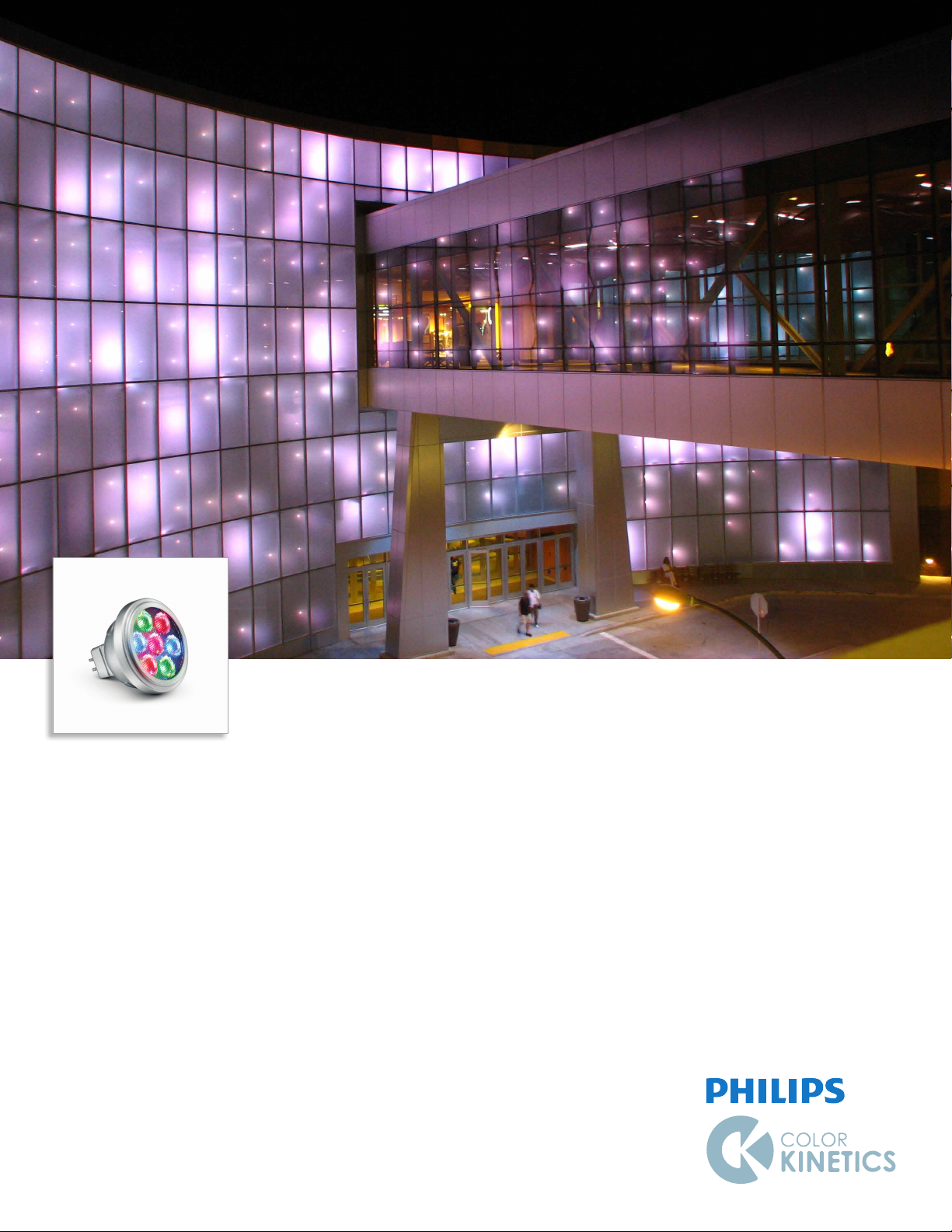
iColor MR gen3
Intelligent RGB MR16 LED lamp for intense, saturated bursts of color
Page 2
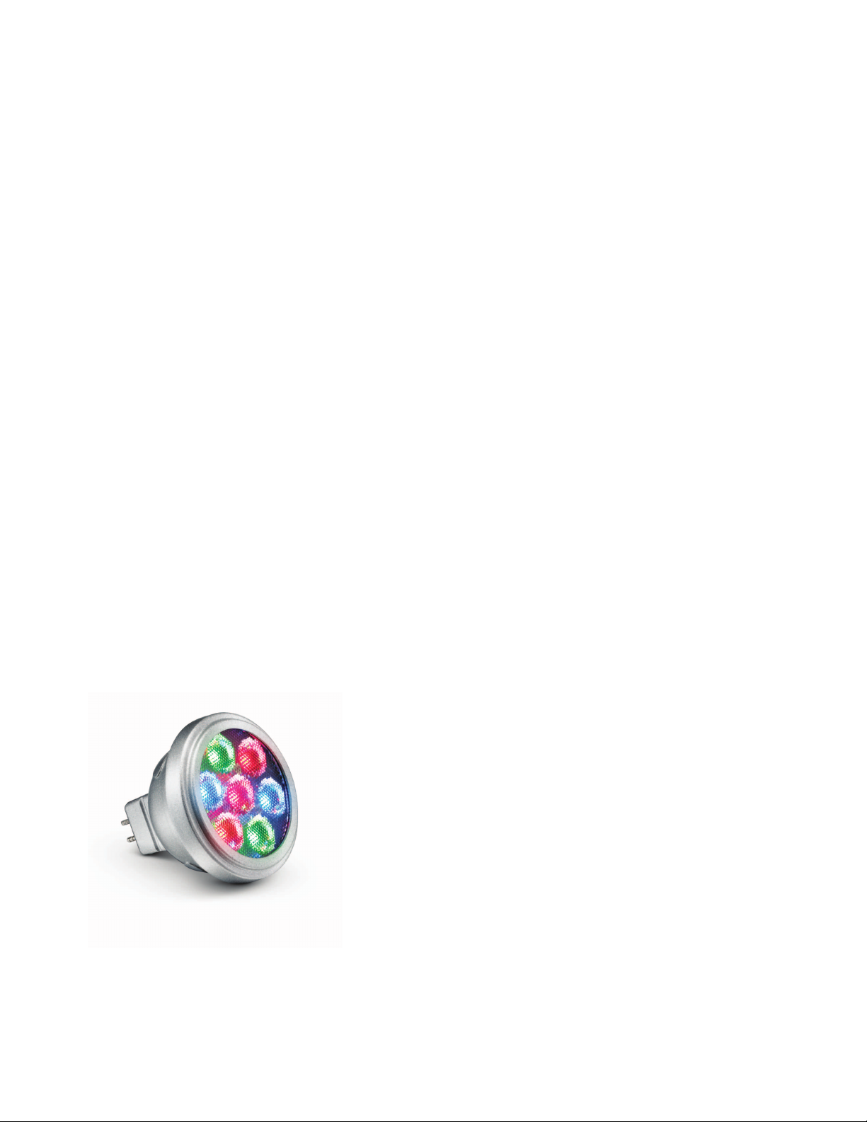
iColor MR gen3
Intelligent RGB MR16 LED lamp for intense, saturated
bursts of color
iColor MR gen3 is an intelligent color-changing lamp that delivers intense, saturated bursts of color and color-
changing effects. The stylish housing ts into most standard MR16 xtures, including tracks, cables, rails, and
pendants. With high-intensity LED light sources and three beam angles, iColor MR gen3 is suitable for a widerange of architectural, theatrical, and retail applications.
• Compatible with most MR16 xtures and sockets
— With its standard GU5.3 base and two-pin
MR16 connector, iColor MR gen3 is compatible
with most MR16 tracks, rails, cables, and pendant
xtures.
• Standard wiring and simple installation — iColor
MR gen3 lamps work with standard 2-conductor
jacketed cable or hook-up wire. Power / data
supplies specically designed for use with iColor
MR gen3 multiplex power and data onto a twowire circuit for use with conventional MR16
xtures and sockets.
• Three beam angles — Use the 17° lamp when you
need a spot of light with sharply dened edges,
the 30° lamps for a wider spread of light, and the
90° (no optic) lamp for a soft, diffuse light.
• Efcient and cost-effective — iColor MR gen3
is easily adaptable to a wide range of interior
environments where MR16 xtures are commonly
used. With long useful source life, low power
draw of just 5 W, and low-maintenance operation,
iColor MR gen3 lamps cost signicantly less to
own and operate than conventional MR16 lamps.
• Industry-leading controls — Works seamlessly
with the complete Philips Color Kinetics line
of controllers, including Light System Manager,
iPlayer
3, and ColorDial Pro, as well as third-
party controllers.
Intense Light Output
iColor MR gen3 lamps output
up to 151 lumens for intense,
saturated bursts of color.
iColor MR gen3 Product Guide2
Page 3
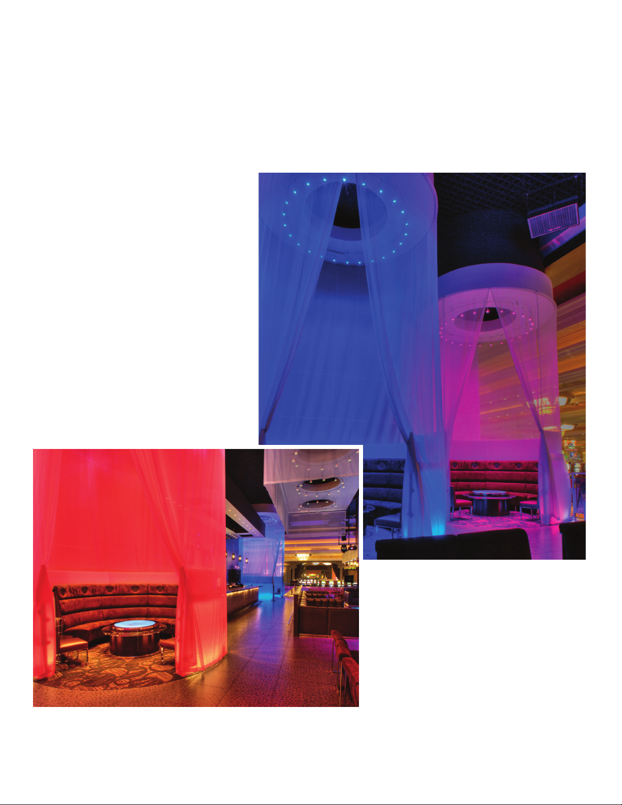
Lighting It Up with iColor MR gen3
iColor MR gen3 intelligent color-changing lamps can be used for stunning effect
wherever conventional MR16 lamps are used — from cruise ships to casinos to
museums and entertainment complexes,
eyecandy sound lounge and bar
Located in the center of Mandalay Bay’s casino floor, eyecandy sound lounge & bar is
a contemporary twist on the typical Las Vegas lounge, featuring an inviting atmosphere
with an ever-changing landscape enabled by full-color LED lighting.
Photography: © Jeff Meyer, shop12
To create a unique vibe, the lighting designer decided
to accentuate various areas of the lounge with color-
changing effects. He created four glowing Party Pods
— circular seating areas that give patrons the ultimate
lighting control. Affixed to a circle track above the seating
areas, iColor MR lamps drench the sheer fabric encasing
the pod in dynamic colorful light. During the lounge’s
off-hours the lighting is controlled to change slowly and
subtly. During operation, however, these elements can be
controlled by the guests via a custom touch-screen to
give patrons a unique, interactive experience.
iColor MR gen3 Product Guide 3
Page 4
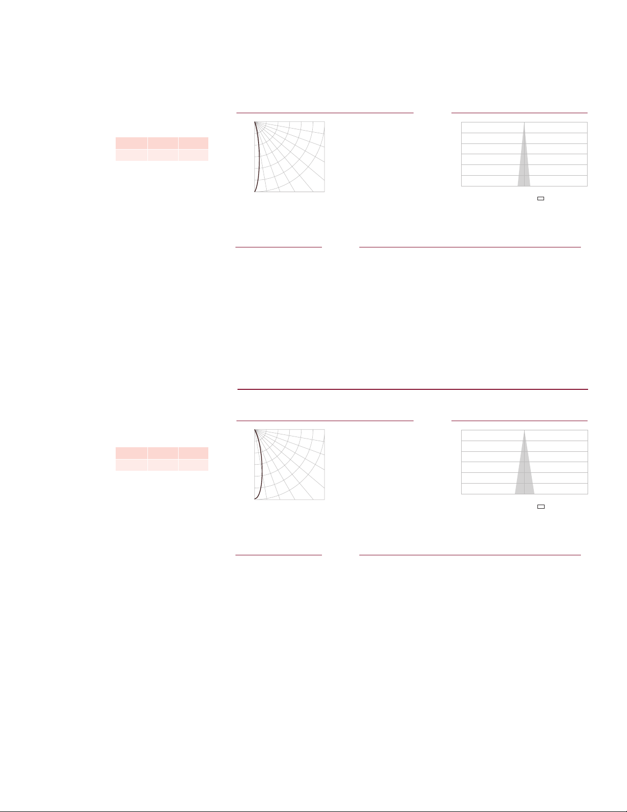
Photometrics
Center Beam fc Beam Width
Effective Floor Cavity Reflectance: 20%
RC 80 70 50 30 10 0
RW 70 50 30 10 70 50 30 10 50 30 10 50 30 10 50 30 10 0
0 119119119119 116116116116 111111111 106106106 102102102 100
1 114112110108 112110108106 106104103 102101100 99 98 97 95
2 110105102 99 107104101 98 101 98 96 98 96 94 95 93 92 90
3 105100 96 92 104 99 95 92 96 93 90 94 91 89 92 89 87 86
4 101 95 91 87 100 94 90 87 92 88 86 90 87 85 88 86 84 82
5 98 91 86 83 96 90 86 82 89 85 82 87 84 81 86 83 80 79
6 95 87 83 79 93 87 82 79 85 81 78 84 81 78 83 80 77 76
7 92 84 79 76 90 84 79 76 82 78 75 81 78 75 80 77 75 74
8 89 81 77 73 88 81 76 73 80 76 73 79 75 73 78 75 72 71
9 86 79 74 71 85 78 74 71 77 73 71 77 73 70 76 73 70 69
10 84 76 72 69 83 76 72 69 75 71 68 74 71 68 74 70 68 67
Effective Floor Cavity Reflectance: 20%
10 85 78 73 70 84 77 73 70 77 73 70 76 72 70 75 72 70 69
Photometric data is based on test results from an independent NIST traceable testing
lab. IES data is available at www.colorkinetics.com/support/ies.
iColor MR gen3
17° beam angle
LED Lumens Efficacy
RGB 143 10.9
Polar Candela Distribution
Cd: 0
143
287
430
573
717
860
10º 20º 30 40º
VA: 0º
-
0º
H
Zonal Lumen
ZONE LUMENS %FIXT
0- 30 118 82.3
0- 40 130 90.7
0- 60 139 97.4
0- 90 143 100.0
90-180 0 0.0
0-180 143 100.0
For lux multiply fc by 10.7
90º
80º
70º
60º
50º
Illuminance at Distance
0 851
5 668
15 148
25 45
35 19
45 8
55 4
65 2
75 1
85 0
90 0
4 ft
8 ft
12 ft
16 ft
20 ft
24 ft
29.2 ft (8.9 m)
1 fc maximum distance
53 fc
13 fc
6 fc
3 fc
2 fc
1 fc
Coefficients Of Utilization - Zonal Cavity Method
1.2 ft
2.4 ft
3.6 ft
4.8 ft
6.0 ft
7.3 ft
Vert. Spread: 17.2º
iColor MR gen3
30° beam angle
LED Lumens Efficacy
RGB 151 11.5
iColor MR gen3 Product Guide4
Polar Candela Distribution
Cd: 0
102
203
305
407
508
610
VA: 0º
10º 20º 30 40º
-
0º
H
Zonal Lumen
ZONE LUMENS %FIXT
0- 30 135 89.6
0- 40 144 95.4
0- 60 149 99.1
0- 90 151 100.0
90-180 0 0.0
0-180 151 100.0
For lux multiply fc by 10.7
Illuminance at Distance
90º
80º
70º
60º
50º
0 600
5 542
15 229
25 51
35 13
45 5
55 2
65 1
75 0
85 0
90 0
Center Beam fc Beam Width
4 ft
8 ft
12 ft
16 ft
20 ft
24 ft
24.5 ft (7.5 m)
1 fc maximum distance
38 fc
9 fc
4 fc
2 fc
2 fc
1 fc
Coefficients Of Utilization - Zonal Cavity Method
RC 80 70 50 30 10 0
RW 70 50 30 10 70 50 30 10 50 30 10 50 30 10 50 30 10 0
0 119119119119 116116116116 111111111 106106106 102102102 100
1 115112110108 112110108107 106105103 103101100 99 98 98 96
2 110106103100 108105102 99 102 99 97 99 97 95 96 95 93 92
3 106101 97 94 105100 96 94 98 95 92 95 93 91 93 91 89 88
4 103 97 93 89 101 96 92 89 94 90 88 92 89 87 90 88 86 84
5 99 93 88 85 98 92 88 85 90 87 84 89 86 83 87 85 83 81
6 96 89 85 81 95 88 84 81 87 83 81 86 83 80 85 82 80 78
7 93 86 81 78 92 85 81 78 84 80 78 83 80 77 82 79 77 76
8 90 83 78 75 89 82 78 75 81 78 75 81 77 75 80 77 74 73
9 87 80 76 73 87 80 76 73 79 75 72 78 75 72 77 74 72 71
1.8 ft
3.6 ft
5.4 ft
7.2 ft
9.0 ft
10.8 ft
Vert. Spread: 25.4º
Page 5

iColor MR gen3
Center Beam fc Beam Width
Cd: 0
7
13
20
27
33
40
VA: 0º
10º 20º 30 40º
90º
80º
70º
60º
50º
-
0º
H
0 36.0
5 35.8
15 34.1
25 30.8
35 26.1
45 20.8
55 14.9
65 9.2
75 4.0
85 0.3
Effective Floor Cavity Reflectance: 20%
RC 80 70 50 30 10 0
RW 70 50 30 10 70 50 30 10 50 30 10 50 30 10 50 30 10 0
0 119119119119 116116116116 111111111 106106106 102102102 100
1 110105102 98 107103100 96 99 96 93 95 93 91 92 90 88 86
2 100 93 86 81 98 91 85 80 87 83 78 84 80 77 81 78 75 73
3 92 82 74 68 90 81 73 68 78 72 67 75 70 65 72 68 64 62
4 85 73 65 58 82 72 64 58 69 63 57 67 61 56 65 60 56 54
5 78 66 57 51 76 65 56 50 62 55 50 61 54 49 59 53 49 47
6 72 59 51 45 70 58 50 44 57 49 44 55 49 44 53 48 43 41
7 67 54 46 40 65 53 45 39 52 44 39 50 44 39 49 43 39 37
8 63 49 41 35 61 49 41 35 47 40 35 46 40 35 45 39 35 33
9 58 45 37 32 57 45 37 32 44 37 32 43 36 32 42 36 31 30
10 55 42 34 29 54 41 34 29 41 34 29 40 33 29 39 33 29 27
ZONE LUMENS %FIXT
0- 30 27.2 31.3
0- 40 43.5 50.1
0- 60 72.8 83.9
0- 90 86.8 100.0
90-180 0.0 0.0
0-180 86.8 100.0
90° beam angle
LED Lumens Efficacy
RGB 87 6.6
Polar Candela Distribution
Illuminance at Distance
4 ft
8 ft
12 ft
16 ft
20 ft
24 ft
6 ft (1.8 m)
1 fc maximum distance
2 fc
1 fc
0 fc
0 fc
0 fc
0 fc
9.5 ft
18.9 ft
28.4 ft
37.9 ft
47.4 ft
56.8 ft
Vert. Spread: 99.6º
Zonal Lumen
For lux multiply fc by 10.7
Coefficients Of Utilization - Zonal Cavity Method
iColor MR gen3 Product Guide 5
Page 6

Specications
Due to continuous improvements and innovations, specifications may change without notice.
Item Specication 17º Beam Angle 30º Beam Angle 90º Beam Angle
Lumens* 143 151 87
Output
Electrical
Control
Physical
Certication
and Safety
* Lumen measurement complies with IES LM-79-08 testing procedures.
† L70 = 70% lumen maintenance (when light output drops below 70% of initial output).
L50 = 50% lumen maintenance (when light output drops below 50% of initial output). Ambient
luminaire temperatures specied. Lumen maintenance calculations are based on lifetime prediction
graphs supplied by LED source manufacturers. Calculations for white-light LED xtures are based on
measurements that comply with IES LM-80-08 testing procedures. Refer to www.philipscolorkinetics.
com/support/appnotes/lm-80-08.pdf for more information.
LED Channels Red / Green / Blue
Lumen Maintenance†
Input Voltage 24 VDC from PDS-70mr
Power Consumption 5 W maximum at full output, steady state
Interface PDS-70mr 24V (DMX / Ethernet)
Control System
Dimensions
(Height x Width x Depth)
Weight 3.1 oz (88 g) 3.0 oz (86 g) 2.9 oz (84 g)
Housing Die-cast zinc, silver nish
Lens Polycarbonate optic Tempered glass
Fixture Connections Standard 2-pin MR16 connector
Temperature Ranges
Humidity 0 – 95%, non-condensing
Maximum Fixture Run
Certications UL / cUL, CE
Environment Dry Location, IP20
100,000 hours L70 @ 40° C 100,000 hours L70 @ 25° C
100,000 hours L50 @ 40° C 100,000 hours L50 @ 25° C
Philips Color Kinetics full range of controllers, including Light
System Manager, iPlayer 3, and ColorDial Pro, or third-party
controllers
1.9 x 1.9 x 1.9 in (49 x 49 x 49 mm)
-4° – 104° F (-20° – 40° C) Operating
-4° – 104° F (-20° – 40° C) Startup
-40° – 176° F (-40° – 80° C) Storage
14 maximum per PDS-70mr
Maximum cable length 50 ft (15 m)
0.25 in
(6 mm)
0.4 in
(10 mm)
1.7 in
(43 mm)
Ø 1.925 in
(49 mm)
Ø 1.5 in
(38 mm)
iColor MR gen3 Product Guide6
Page 7

Included in the box
iColor MR gen3 lamp
Installation Instructions
Fixtures and Accessories
iColor MR gen3 lamps are part of a complete low-voltage system which includes:
• One or more PDS-70mr 24V power / data supplies
• Low-voltage 2-wire track (without transformer) or compatible MR16 fixtures wired
in parallel
• Any Philips controller, including Light System Manager and iPlayer 3, or a third-party
DMX controller
Item Type Item Number Philips 12NC
17° beam angle 101-000074-00 910503704252
iColor MR gen3
PDS-70mr 24V Power / Data Supply
30° beam angle 101-000074-01 910503704288
90° beam angle 101-000074-02 910503704289
Pre-programmed 109-000018-00 910503700098
DMX 109-000018-01 910503700099
Ethernet 109-000018-02 910503700583
Use Item Number when ordering in North America.
Typical iColor MR gen3 installation
For detailed wiring diagrams visit
www.colorkinetics.com/support/wiring/ls_prod.html
iColor MR gen3
PDS–70mr 24V
Power / Data Supply
Controller
Keypad
OFF
Input from
Controller
Keypad
PRESETS
2
3
iPlayer 3
Controller
iPLAYER 3
4
5
USB
X
POWER
iColor MR gen3 Product Guide 7
Page 8

Installation
iColor MR gen3 is an intelligent color-changing lamp that delivers intense, saturated
bursts of color and color-changing effects. The stylish housing ts into most standard
MR16 xtures, including tracks, cables, rails, and pendants. Fourteen iColor MR gen3
lamps can be powered by one PDS-70mr 24V.
Owner / User Responsibilities
It is the responsibility of the contractor, installer, purchaser, owner, and user to
install, maintain, and operate iColor MR gen3 in such a manner as to comply with all
applicable codes, state and local laws, ordinances, and regulations. Consult with the
appropriate electrical inspector to ensure compliance.
Planning Your Installation
Like conventional MR lamps, iColor MR gen3 color-changing LED lamps plug directly
into compatible MR16 fixtures. iColor MR gen3 lamps are compatible with many, but
not all, MR16 fixtures. Keep the following considerations in mind as you plan your
installation:
• iColor MR gen3 lamps plug into many standard, low-voltage MR16 lighting tracks,
cables, rails, pendants, and other xtures. iColor MR gen3 will not work with
MR16 xtures that have individually attached transformers.
• iColor MR gen3 lamps require adequate ventilation around the lamp housing to
ensure peak performance and maximize useful life. Using iColor MR gen3 lamps in
sealed xtures and recessed xtures, therefore, is not recommended. Using iColor
MR gen3 within small enclosures is recommended only if the enclosed space is
adequately vented or cooled.
E Refer to the iColor MR gen3 Installation
Instructions for specic warning and caution
statements.
• Because iColor MR gen3 lamps weigh more than traditional MR16 lamps and could
loosen with use and vibration, use xtures and lamp holders that have locking
devices. Failure to do so could result in property damage and personal injury.
• Do not install iColor MR gen3 lamps on the same xture, track, rail, or cable with
any other type of MR16 lamp.
• iColor MR gen3 lamps work only with PDS-70mr 24V power / data supplies
(DMX, Ethernet, or Pre-Programmed).
Create a Lighting Design Plan
and Layout Grid
1. Select compatible low-voltage MR16 xtures, and follow the manufacturer’s
guidelines for installation and wiring.
2. Determine the appropriate location of each PDS-70mr 24V power / data supply in
relation to the MR16 xtures.
Each PDS-70mr 24V can power up to 14 iColor MR gen3 lamps in a single run.
The farthest lamp in the run can be no more than 50 ft (15 m) from the PDS-70mr
24V. Refer to the PDS-70mr 24V documentation for guidelines on conguring and
positioning the PDS-70mr 24V in relation to the controller.
3. On an architectural diagram or other diagram that shows the physical layout of
the installation, identify the locations of all switches, controllers, power supplies,
xtures, and cables.
4. Each iColor MR gen3 lamp comes pre-programmed with a unique serial number.
As you unpack the lamps, record the serial numbers in a layout grid (typically a
spreadsheet or list) for easy reference and light addressing.
5. Assign each xture and lamp to a position in the lighting design plan.
iColor MR gen3 Product Guide8
00000000
Page 9

To additional power / data supplies
iPlayer 3
DMX Installation with iPlayer 3
Controller
Controller
Keypad
DMX Data
Serial Cable
PDS-70mr 24V DMX
Ethernet Installation with Light System Manager
100 – 240 VAC
iColor MR gen3
Light System
Manager
Ethernet
Switch
Cat-5e Cable
Cat-5e Cable
PDS-70mr 24V Ethernet
or Ethernet switches (up to 3 levels)
Ethernet Data
100 – 240 VAC
iColor MR gen3
iColor MR gen3 Product Guide 9
Page 10

Install the Fixtures and Lamps
Make sure the power is OFF before installing MR16 fixtures and iColor MR gen3
lamps.
1. Install all power / data supplies, including any interfaces with controllers.
2. Verify that all additional supporting equipment (switches, controllers) is in place.
3. Install compatible low-voltage MR16 xtures following the manufacturer’s
instructions, adhering to all safety precautions.
4. Plug the iColor MR gen3 lamps into the MR16 xtures.
E Refer to the PDS-70mr 24V Installation
Instructions or Product Guide for guidelines
on conguring and positioning the PDS-
70mr 24V in relation to the controller.
Address and Congure the Lamps
Make sure the power is ON before addressing and configuring fixtures.
You address and configure iColor MR gen3 lamps using QuickPlay Pro addressing and
configuration software, which you can download for free from
www.philipscolorkinetics.com/support/addressing/
Addressing iColor MR gen3 Lamps
iColor MR gen3 lamps operate in 8-bit mode by default. You can configure iColor MR
gen3 lamps to operate in 16-bit mode, which increases fixture resolution for smoother
dimming.
In 8-bit mode, fixtures use one DMX address per LED channel (red, green, and blue). In
16-bit mode, fixtures use two DMX addresses per LED channel. The first DMX address
corresponds to the “coarse” data for that channel, and the second corresponds to
the “fine” data. By using double the number of DMX addresses, 16-bit mode increases
fixture resolution from 256 dimming steps to 65,536 (256 x 256) dimming steps.
DMX Address Assignments
8-Bit Mode
16-Bit Mode
Red Coarse Red Fine Green Coarse Green Fine Blue Coarse Blue Fine
1 2 3
Red Green Blue
1 2 3 4 5 6
iColor MR gen3 Product Guide10
Page 11

iColor MR gen3 lamps come factory-addressed with a starting DMX address of 1. For
video displays and light show designs that require different lamps to show different light
output simultaneously, you must assign unique DMX addresses to your lamps and sort
them in a useful order:
E For lighting designs where lamps work in
unison, all lamps can be assigned the same
starting DMX address. Changes to the default
starting DMX address is not necessary, but if
lamps were previously readdressed for use in
other installations, you must reset them.
• In Ethernet installations, you can address and congure your lamps using QuickPlay
Pro with a computer connected to your lighting installation’s network. QuickPlay Pro
can automatically discover all of your lamps, controllers, and PDS-70mr 24V devices
for quick conguration.
• In DMX installations, you can address and congure your lamps using QuickPlay
Pro with iPlayer 3 or SmartJack Pro. You can manually enter lamp serial numbers, or
you can import a spreadsheet listing each lamp’s serial number and starting DMX
address.
Setting Lamp Dimming Curve
Dimming curves describe how slowly or quickly a lamp dims at different levels of
input. For ner control, iColor MR gen3 lamps offer three different dimming curves
for use in different situations and applications:
• Normal
The non-linear (gamma) dimming curve used in most Philips Color Kinetics LED
lighting xtures. iColor MR gen3 lamps use the normal dimming curve by default.
• Linear
A dimming curve with a linear relationship between power input and DMX output.
• Tungsten
A non-linear dimming curve that emulates the dimming curve of incandescent lamps
on a DMX dimmer. This curve offers the most control at low intensities.
Setting LED Transition Speed
Normally, LEDs react to DMX or other control data instantaneously. In some cases,
you may want to slow down the reaction speed to achieve smoother transitions
when the intensity of different LED channels changes. iColor MR gen3 lamps offer ve
levels of decreasing LED transition speed, from Fast (instant snap changes) to Delay- 4
(slowest transition speed).
iColor MR gen3 Product Guide 11
Page 12

Philips Color Kinetics
3 Burlington Woods Drive
Burlington, Massachusetts 01803 USA
Tel 888.385.5742
Tel 617.423.9999
Fax 617.423.9998
www.colorkinetics.com
Copyright © 2013 Philips Solid-State Lighting Solutions, Inc. All rights reserved.
Chromacore, Chromasic, CK, the CK logo, Color Kinetics, the Color Kinetics logo, ColorBlast,
ColorBlaze, ColorBurst, ColorGraze, ColorPlay, ColorReach, iW Reach, eW Reach, DIMand,
EssentialWhite, eW, iColor, iColor Cove, IntelliWhite, iW, iPlayer, Optibin, and Powercore are
either registered trademarks or trademar ks of Philips Solid-State Lighting Solutions, Inc. in the
United States and / or other countries. All other brand or product names are trademar ks or
registered trademarks of their respective owners. Due to continuous improvements and innovations,
specifications may change without notice.
Cover Photo: Welcome Wall at Potawatomi Bingo Casino, Milwaukee, Wisconsin, USA,
by Marty Peck, Creative Lighting Design & Engineering
DAS-0000312-00 R00 04-13
 Loading...