

Philips XENIUM DUAL BAND Service Manual
Philips Consumer Communications
CUSTOMER SERVICES
Author : Fabrice TANT
Approval : Jean Pierre HOLLANDE
Operational manager
SERVICE REPAIR SUPPORT
PROCEDURE
PCC/VY/691/E/XENIUMDB989LVL1/0025/MLD/MLD
Revision : 2
Date : 19/06/2000
Page 1 out of 24
PHILIPS
SERVICE MANUAL
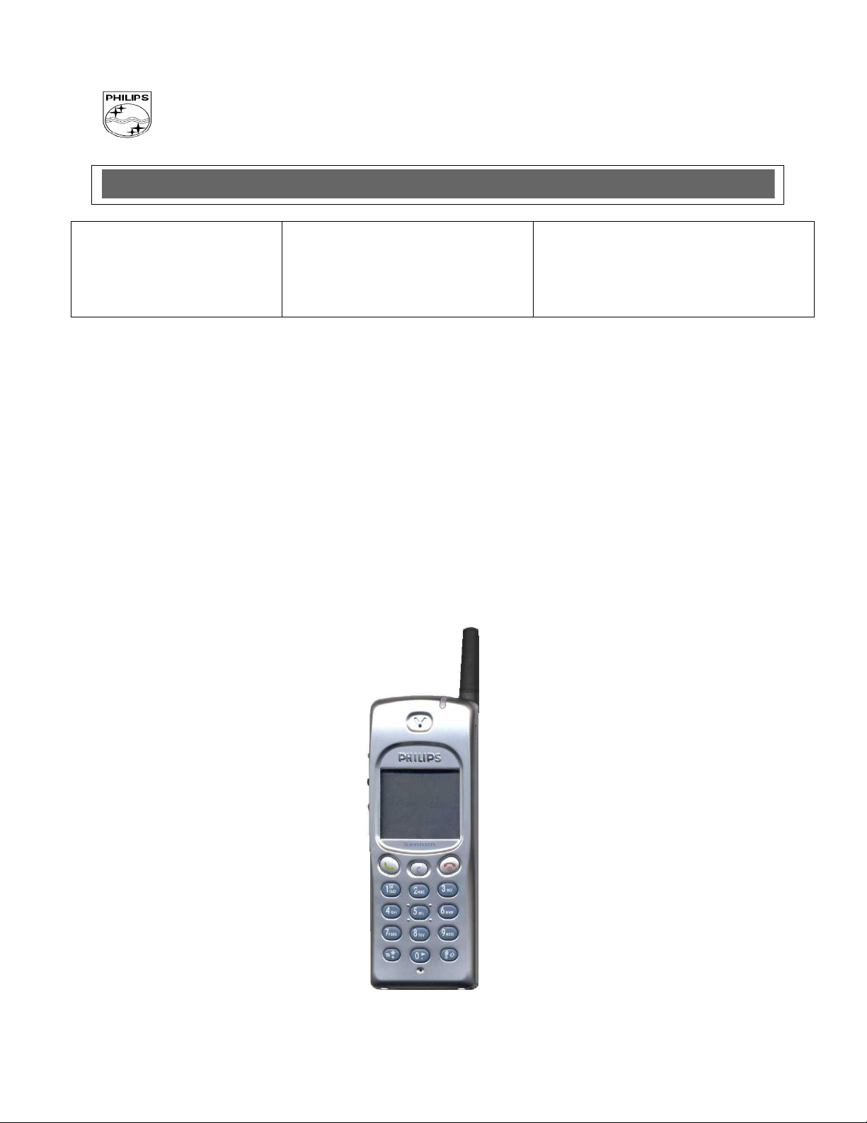
Repair for Cellular Telephone
XENIUM DUAL BAND
LEVEL 1
PCC/VY/691/E/XENIUM989/0025/MLD/MLD
- 1 -
Philips Consumer Communications
CUSTOMER SERVICES
Author : Fabrice TANT
Approval : Jean Pierre HOLLANDE
Operational manager
SERVICE REPAIR SUPPORT
PROCEDURE
PCC/VY/691/E/XENIUMDB989LVL1/0025/MLD/MLD
Revision : 2
Date : 19/06/2000
Page 2 out of 24
DATE
MODIFICATION
PAGE
19/06/2000
CREATION
Revision 2 : 26/07/2000
- Modification of components list
Page 23
PHILIPS
Service Manual
Last updates:
PCC/VY/691/E/XENIUM989/0025/MLD/MLD
- 2 -

Philips Consumer Communications
CUSTOMER SERVICES
Author : Fabrice TANT
Approval : Jean Pierre HOLLANDE
Operational manager
SERVICE REPAIR SUPPORT
PROCEDURE
PCC/VY/691/E/XENIUMDB989LVL1/0025/MLD/MLD
Revision : 2
Date : 19/06/2000
Page 3 out of 24
PHILIPS
1.0 PURPOSE ------------------------------------------------------------------------------------------------------------------------------- 4
2.0 SCOPE ----------------------------------------------------------------------------------------------------------------------------------- 4
3.0 REFERENCE -------------------------------------------------------------------------------------------------------------------------- 4
4.0 GLOSSARY/ACRONYM LIST ---------------------------------------------------------------------------------------------------- 4
5.0 TEST EQUIPMENT AND TOOLS ------------------------------------------------------------------------------------------------ 4
6.0 TEST AND INSPECTION PLAN -------------------------------------------------------------------------------------------------- 5
6.1 USER INTERFACE TEST ------------------------------------------------------------------------------------------------------------------- 5
6.2 RF TEST ------------------------------------------------------------------------------------------------------------------------------------ 5
7.0 BEFORE STARTING ---------------------------------------------------------------------------------------------------------------- 6
7.1 DESCRIPTION OF THE TRANSCEIVER --------------------------------------------------------------------------------------------------- 6
7.2 DESCRIPTION OF THE DISPLAY ---------------------------------------------------------------------------------------------------------- 7
7.3 USING THE CAROUSEL ------------------------------------------------------------------------------------------------------------------- 8
7.4 INSERTING THE MICRO-SIM CARD --------------------------------------------------------------------------------------------------- 9
7.5 INSERTING ON THE BATTERY ------------------------------------------------------------------------------------------------------------ 9
7.6 REMOVING THE BATTERY -------------------------------------------------------------------------------------------------------------- 10
7.7 CHARGING THE BATTERY --------------------------------------------------------------------------------------------------------------- 10
8.0 TEST PROCEDURES --------------------------------------------------------------------------------------------------------------- 11
8.1 INITIAL FUNCTIONAL CHECK FOR TCD989/J XENIUM --------------------------------------------------------------------------- 11
8.2 RF TEST ---------------------------------------------------------------------------------------------------------------------------------- 15
8.3 CHARGING IGN (IGNITION) – BATTERY---------------------------------------------------------------------------------------------- 18
9.0 ASSEMBLY / DISMANTLEMENT PROCEDURES ------------------------------------------------------------------------- 19
9.1 DISMANTLEMENT ------------------------------------------------------------------------------------------------------------------------ 19
9.2 ASSEMBLY -------------------------------------------------------------------------------------------------------------------------------- 19
10.0 DEFAULTS SETTINGS ------------------------------------------------------------------------------------------------------------ 20
10.1 RESET CUSTOMER PARAMETERS. ------------------------------------------------------------------------------------------------------ 20
10.2 USE OF THE GSM STRING *#RSAV*# OR *#7728*#. ----------------------------------------------------------------------------- 20
11.0 SOLUTIONS IN CASE OF PROBLEMS DURING THE TESTS --------------------------------------------------------- 21
11.1 THE PHONE DOES NOT SWITCH ON. ---------------------------------------------------------------------------------------------------- 21
11.2 CHARGE DOES NOT START OR NO DETECTION OF THE CHARGER. ----------------------------------------------------------------- 21
11.3 THE DISPLAY SHOWS “NO SIM CARD. PLEASE INSERT YOUR SIM CARD.” OR “SIM FAILURE” -------------------------- 21
11.4 DISPLAY PROBLEMS --------------------------------------------------------------------------------------------------------------------- 22
11.5 BUZZER PROBLEMS ---------------------------------------------------------------------------------------------------------------------- 22
11.6 NO SOUND IN LOUDSPEAKER ---------------------------------------------------------------------------------------------------------- 22
11.7 COMMUNICATION PROBLEMS ---------------------------------------------------------------------------------------------------------- 22
11.8 DEFECTIVE ANTENNA ------------------------------------------------------------------------------------------------------------------- 22
11.9 KEYBOARD PROBLEMS ------------------------------------------------------------------------------------------------------------------ 22
11.10 PROBLEMS TO SEND SMS MESSAGES ---------------------------------------------------------------------------------------------- 23
12.0 RECOMMENDED PART LIST- TCD 989 XENIUM DB ------------------------------------------------------------------- 23
12.1 COMMON PARTS – OUT OF WARRANTY ----------------------------------------------------------------------------------------------- 23
- 3 -
PCC/VY/691/E/XENIUM989/0025/MLD/MLD
CONTENTS
Philips Consumer Communications
CUSTOMER SERVICES
Author : Fabrice TANT
Approval : Jean Pierre HOLLANDE
Operational manager
SERVICE REPAIR SUPPORT
PROCEDURE
PCC/VY/691/E/XENIUMDB989LVL1/0025/MLD/MLD
Revision : 2
Date : 19/06/2000
Page 4 out of 24
Window or Bezzel
Protective plastic over the LCD display
SW
Software
PN
Hardware Configuration of the Mobile
CN
Matrix for Types of SW used on the different hardware
HW
Hardware
ASC
Authorized Service Center
NSC
National Service Center
Test SIM Card
Used for functionality of PHILIPS Mobiles
Test SIM Card “SP”
SIM Card that is used to stimulate the user interface and allow radio tests
PHILIPS
1.0 PURPOSE
This document establishes the functional test and inspection procedures for the first level service repair of the
XENIUM DB transceiver
2.0 SCOPE
The test plan is applicable to all levels of service repair of the XENIUM DB transceiver
3.0 REFERENCE
4.0 GLOSSARY/ACRONYM LIST
5.0 TEST EQUIPMENT AND TOOLS
Equipment / Tools
Production Test SIM Card - Part No. : 4311 255 00781
Test SIM Card “SP” - Part No. : 4311 255 00782
RF Cable - Part No. : 941-555-1 (AMP).
Digital Multimeter - Recommended Model : Fluke
Specification with current reading in mA.
Digital Radiocommunication Tester.
PCC/VY/691/E/XENIUM989/0025/MLD/MLD
- 4 -
Philips Consumer Communications
CUSTOMER SERVICES
Author : Fabrice TANT
Approval : Jean Pierre HOLLANDE
Operational manager
SERVICE REPAIR SUPPORT
PROCEDURE
PCC/VY/691/E/XENIUMDB989LVL1/0025/MLD/MLD
Revision : 2
Date : 19/06/2000
Page 5 out of 24
PHILIPS
6.0 TEST AND INSPECTION PLAN
The test plan is derived from the Product Test Reference for XENIUM DB.
6.1 User Interface Test
Use the Test SIM card “SP” / Production to test the transceiver as follows :
On/off Button
LCD Backlight
Keyboard Test
Buzzer Test
Audio Test
Antenna Test (levels 5 &10)
LCD
LED Test (On/Off)
IMEI
Tester Status/Eeprom Status
With a fast charger connected with the PRODUCT’s bottom connector, check the full scrolling from one mode to the
next when charging IGN (Ignition)-Battery.
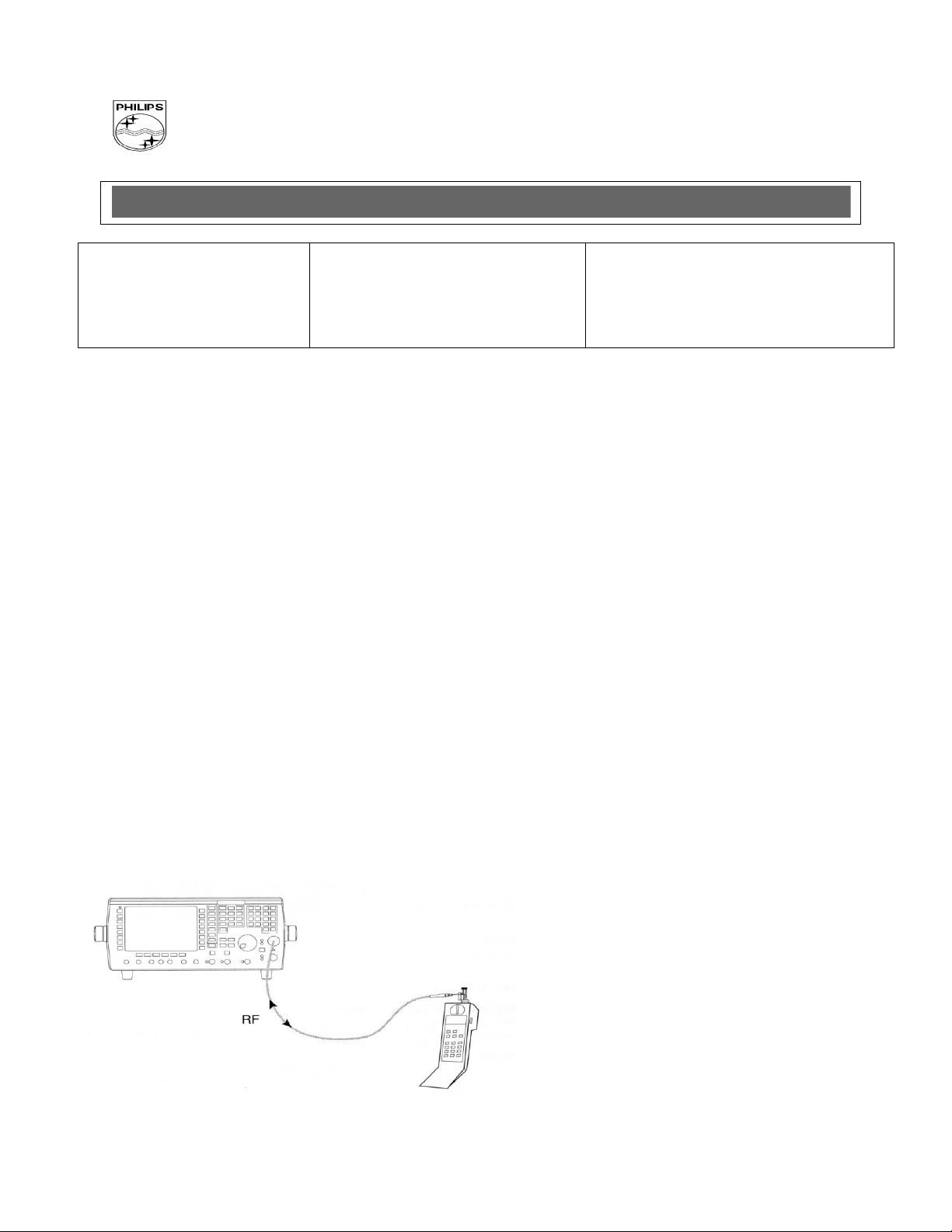
6.2 RF Test
The radio test must be performed with a Digital Radio Test Set connected to the mobile RF connector with the
specific RF cable
PCC/VY/691/E/XENIUM989/0025/MLD/MLD
- 5 -
Philips Consumer Communications
CUSTOMER SERVICES
Author : Fabrice TANT
Approval : Jean Pierre HOLLANDE
Operational manager
SERVICE REPAIR SUPPORT
PROCEDURE
PCC/VY/691/E/XENIUMDB989LVL1/0025/MLD/MLD
Revision : 2
Date : 19/06/2000
Page 6 out of 24
PHILIPS
7.0 BEFORE STARTING
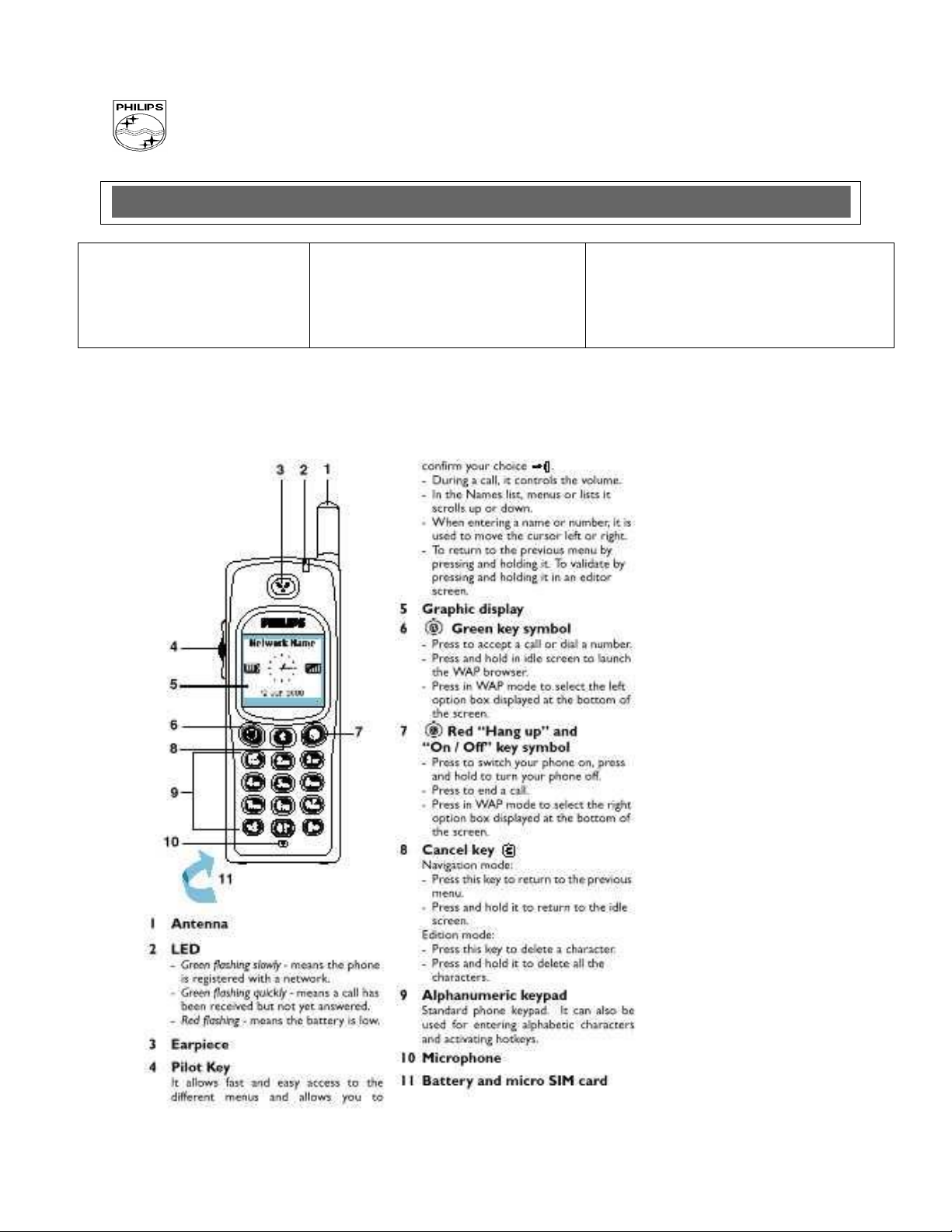
7.1 Description of the transceiver
PCC/VY/691/E/XENIUM989/0025/MLD/MLD
- 6 -
Philips Consumer Communications
CUSTOMER SERVICES
Author : Fabrice TANT
Approval : Jean Pierre HOLLANDE
Operational manager
SERVICE REPAIR SUPPORT
PROCEDURE
PCC/VY/691/E/XENIUMDB989LVL1/0025/MLD/MLD
Revision : 2
Date : 19/06/2000
Page 7 out of 24
PHILIPS
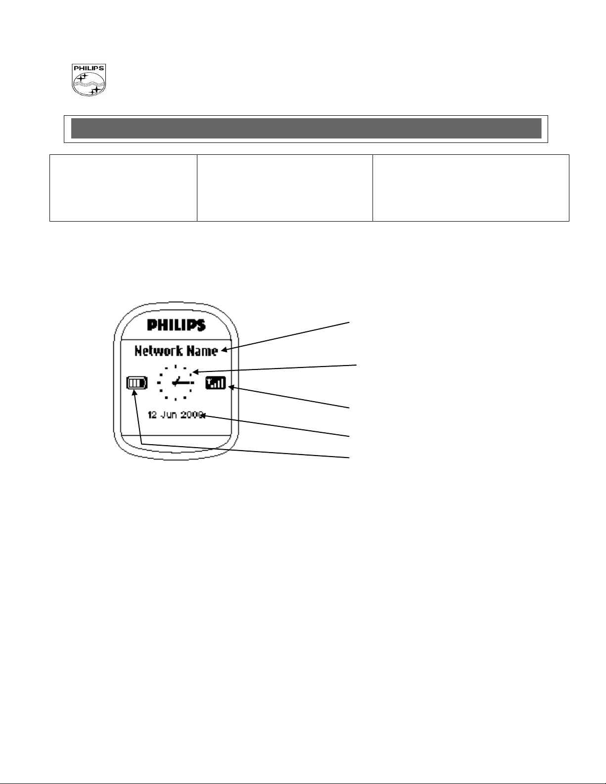
7.2 Description of the display
Indicates the Network on which
your phone is registered.
Clock : Indicates an hour.
Reception quality : The more bars shown
the better the reception.
Indicates the date
Battery level : The bars indicate the battery level
(4 Bars means full, no bars means recharging is
needed.)
PCC/VY/691/E/XENIUM989/0025/MLD/MLD
- 7 -
Philips Consumer Communications
CUSTOMER SERVICES
Author : Fabrice TANT
Approval : Jean Pierre HOLLANDE
Operational manager
SERVICE REPAIR SUPPORT
PROCEDURE
PCC/VY/691/E/XENIUMDB989LVL1/0025/MLD/MLD
Revision : 2
Date : 19/06/2000
Page 8 out of 24
PHILIPS
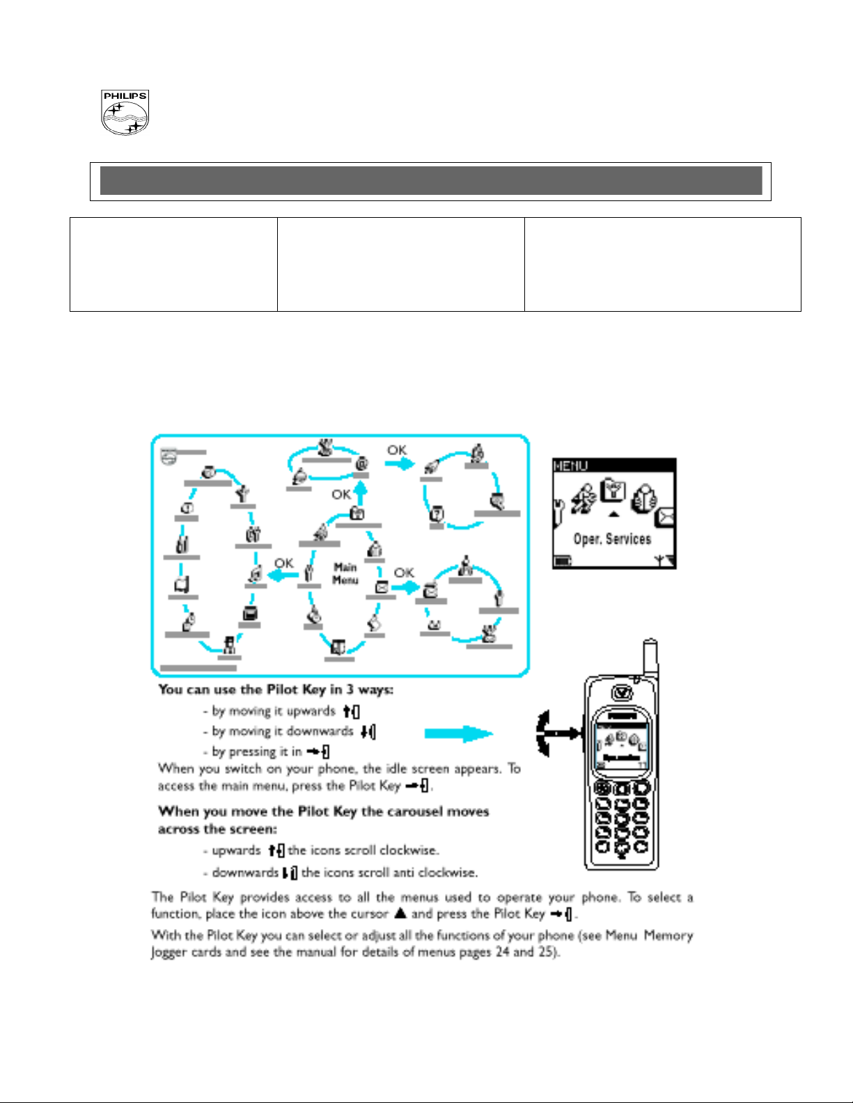
7.3 Using The Carousel
The carousel is a circular loop of icons displayed on the screen. These icons provide access to the different
menus and sub menus used to operate your phone.
PCC/VY/691/E/XENIUM989/0025/MLD/MLD
- 8 -
 Loading...