

Page 1
Important notes for users in the U.K.
Warning: to prevent fire or shock hazard, do not expose
camera or monitor to rain or moisture.
The lightning flash with arrowhead
symbol, within a triangle, is intended to
alert the user to the presence of
uninsulated “dangerous voltage” within
the product’s enclosure; that may be of
sufficient magnitude to constitute a risk
of electric shock to persons.
Caution: to reduce the risk of electric shock, do not remove
cover (or back). No user serviceable parts inside. Refer servicing
to qualified service personnel.
The exclamation mark within a triangle is
intended to alert the user to the presence
of important operating and maintenance
(servicing) instructions in the literature
accompanying the appliance.
If the fitted plug is not suitable for your mains socket,
it should be removed and be replaced by an appropriate
plug.
How to replace a plug
• Cut the mains plug from the lead.
• Strip the sheathing so the wires will become free for
the necessary length to connect the UK-mains plug (not
supplied).
The wires in the mains lead are coloured according to
the following code: blue=neutral (N), brown=live (L).
As these colours may not correspond with the colour
markings identifying the terminals in your plug, proceed
as follows:
• Connect the blue wire to the terminal marked N or
coloured black.
• Connect the brown wire to the terminal marked L or
colewort red.
Caution
Do not connect either wire to the earth terminal in the
plug, marked E (or) or coloured green (or green and
yellow).
Before replacing the plug cover, make certain that the
cord grip is clamped over the sheath of the lead, not
simply over the two wires.
Electro Magnetic Compatibility
(EMC)
This equipment complies with the European rules EMC
according to EN55013, EN55020 and EN50082-1.
The equipment conforms with the EMC directive and
low-voltage directive.
This device complies with EMC rules under test
conditions that included use of system cables and
connectors between system components. If you have any
problems, contact your dealer.
Warning
Any unauthorized modification to this equipment may cause
violation of the EMC rules resulting in the revocation of the
authorization to operate the equipment.
Note: we advise you to use the following types of mains
power adapters in combination with the camera:
U.K. Philips VCM1162/01R
EUR Philips VCM1162/00R
Fuse
If the mains plug (or adapter) contains a fuse, the value
of this fuse should be 3 Amp. Alternatively, if another
type of plug (not fused) is used, the fuse at the
distribution board should not be greater than 5 Amp.
2
Page 2
Colour Observation Monitor
English
Table of contents
Introduction...............................................................................................3
Connection and operation facilities......................................4
Installation..................................................................................................4
Placement and connection
Settings
Cable length selector
Last in line switch
Input selection switch
Operation ..................................................................................................6
Power on/off
Power save/active
Alarm...............................................................................................................6
Monitor is used as slave monitor
When an alarm occurs
Reset alarm
Monitor is used as stand-alone system
Trouble shooting
System cable .............................................................................................7
Tips for maintenance.........................................................................7
Englishg
Page
Introduction
By purchasing our ‘Colour Observation Monitor’ you
possess an easy to operate set for expansion of your
observation and security system with more observation
posts.
Used as a slave monitor it provides the same camera
image and sound as the system monitor. The monitor is
fitted with a loop-through connector to which a
following slave monitor can be connected.
The ‘Colour Observation Monitor’ can also be used as a
stand-alone system. In this way you can use the slave
monitor as a one camera surveillance system. The
monitor provides an input for a Philips system camera.
The monitor also has an auxiliary input which can be
used for any video and audio baseband signal, such as a
VCR (playback only).
The following items are included in this kit:
1 Colour Observation Monitor
1 System cable (25m/75ft)
1 User manual
>
N
<
E
R
A
A
R
F
6 6
>
N
<
E
R
A
A
R
F
8
7
4
4 4
Colour Observation system
talkaction menu
4
1
_
view
auto
+ next
4
4
2
3
Colour Observation Monitor
Colour Observation Monitor
CL 66610005_005a.AI
5
4
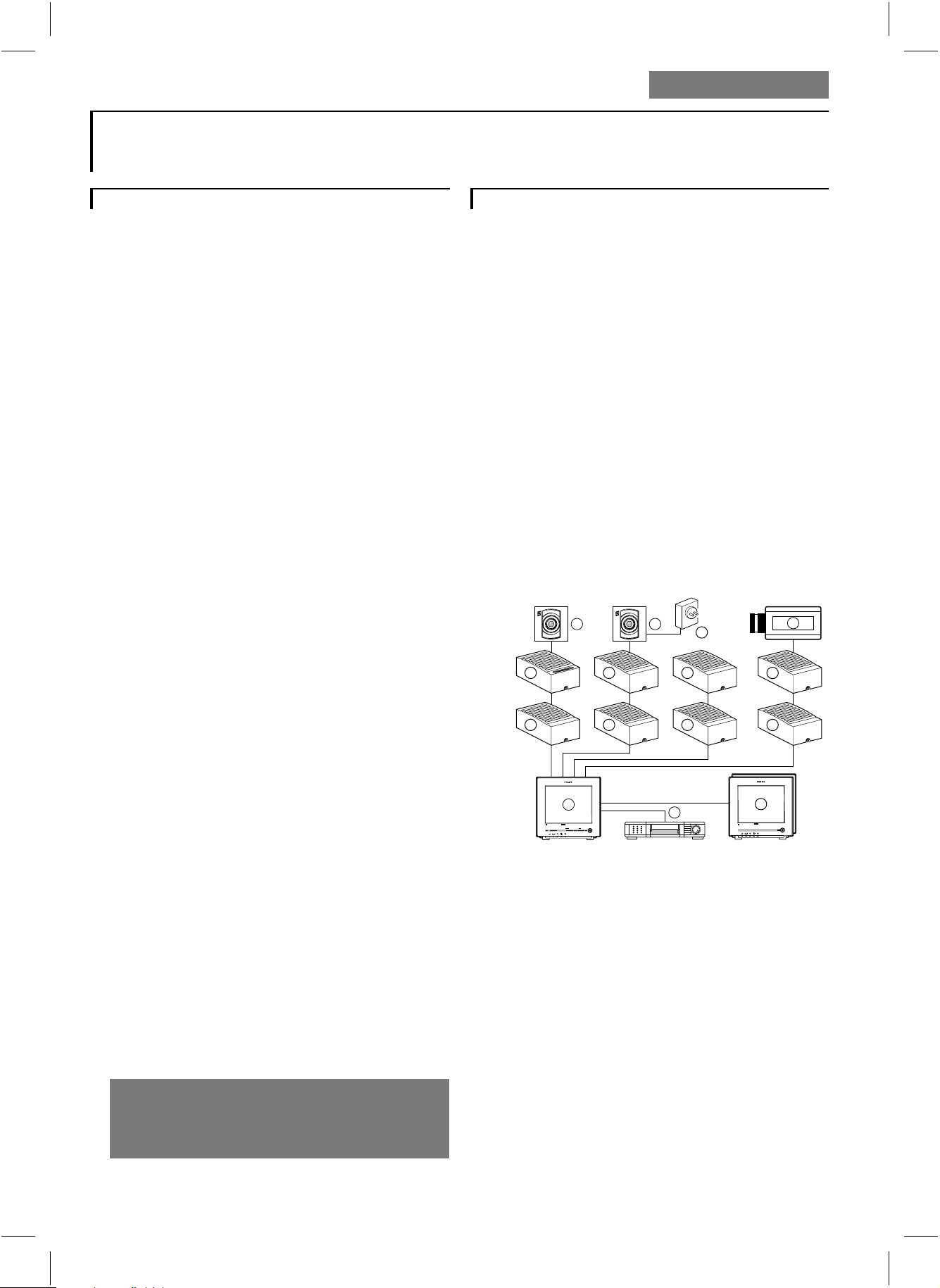
1 System monitor
2 Video recorder (VCR)
3 Slave monitor(s) (max. 3)
4 Accessary boxes (0-2 per cable)
5 Interface box
6 System cameras
7 Non system camera’s (CVBS)
8 Mains power adapter
Mains supply:
The monitor accepts a mains power voltage of
100-240V~, 50/60Hz.
When the monitor is used as a stand alone system, it
supplies a safe low-voltage (16-32V _) for a camera.
Read these instructions, before putting your system in
operation.
3
g
Page 3
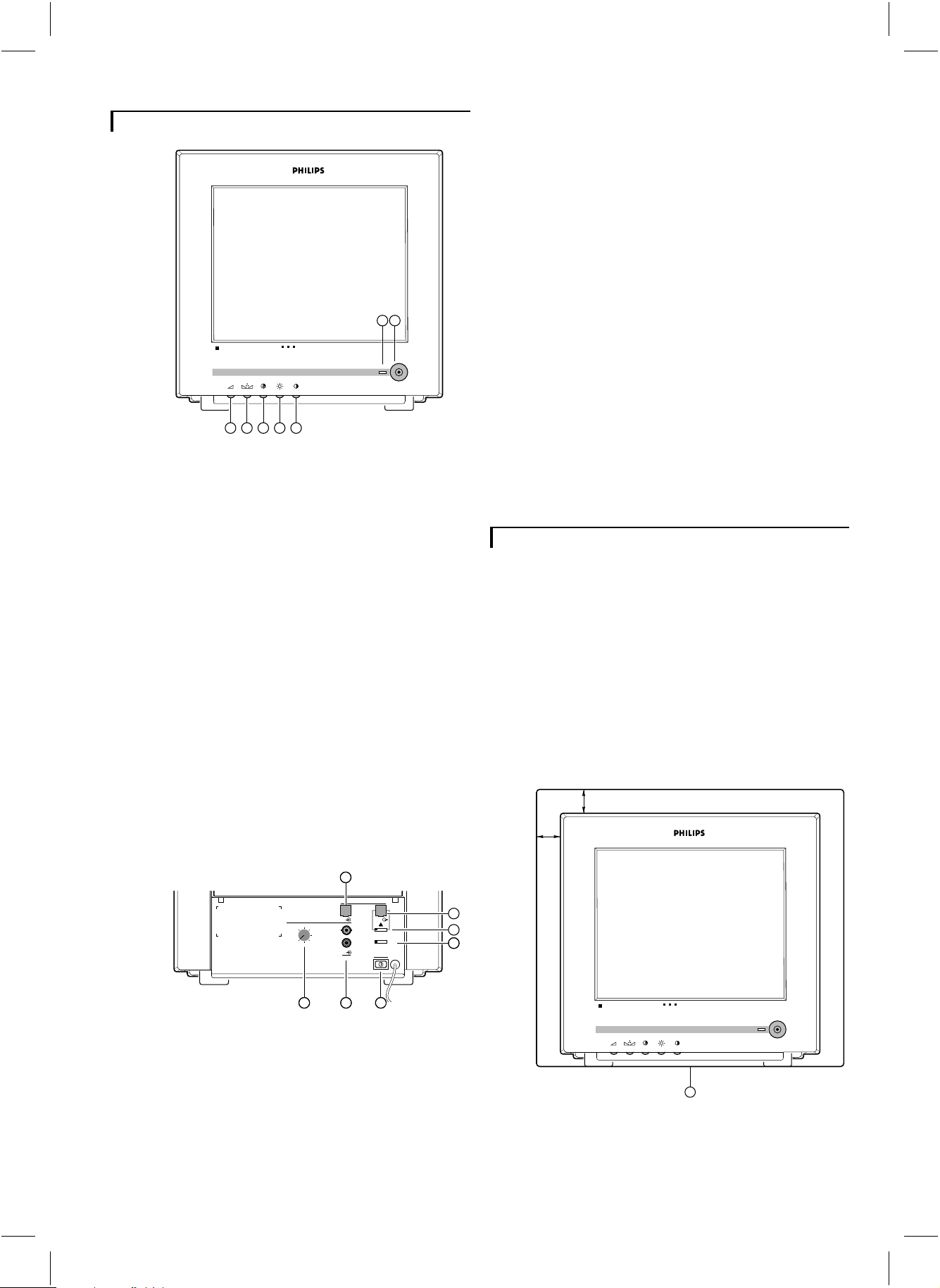
Connection and operation facilities
67
Colour Observation Monitor
12345
1 Volume
Volume control for the audio signal.
Hue
2
Q
q
Hue control
Remark: For the Europe version this control has no function.
CL 66610005_202.AI
Aux. in (aux. in)
9
Input for a third party camera or VCR (playback only).
Mains power switch (power)
10
Switches the slave monitor on/off.
Slave input (slave in)
11
This input has to be connected to the output of the
system monitor.
Remark: When the slave monitor is not connected to a system
monitor (stand alone) you can use this input to connect a
system camera.
Slave out (slave out)
12
Output for a second or third slave monitor.
Last in line switch (slave out 1/0)
13
Set the switch to 1 if another slave monitor is connected
to this output.
Input selection switch (in slave/aux)
14
With this switch you can select which input is displayed
on the monitor screen.
Installation
Colour
3
S
Colour intensity control
Brightness
4
(
Brightness control
Contrast
5
T
Contrast control
System mode indication LED
6
The following modes are possible:
• power on (LED is green)
• power save mode (LED is red)
• silent function (LED is amber)
• alarm during power silent function (LED is red blinking)
Power save/active
7
P
Image and audio of the monitor on/off.
11
slave
200m
300m
in out
video
audio
IO
in
slaveaux
in
power
aux
cable length
100m
0-50m
In this chapter the installation of the slave monitor is
described.
Caution: When (dis)connecting the slave monitor always
ensure that the slave monitor and system monitor are switched
off by means of the rear power switch. Only operating the
power save button is not sufficient.
Placement and connection
1 Place the slave monitor on a solid base (leave at least
3cm around each side of the monitor for ventilation).
3 cm
3 cm
12
13
14
1098
CL 66610005_203.AI
Cable length selector (cable length)
8
The value of this selector must be set to the length of the
system cable (0-300m max.) between the slave monitor
and system monitor.
g
Colour Observation Monitor
1
CL 66610005_204.AI
4
Page 4

2a Monitor is used as stand alone system:
Connect a system camera to the slave-in input (11).
A third party camera can be connected to the aux. in
input (9).
2b Monitor is used as slave monitor:
See figure at the top of the page.
Connect the slave monitor to the system monitor (16).
Remark: If a second slave monitor is used, it has to be
connected to the slave-out (12) output.
This selector adapts the slave monitor input to the length
of the system cable connecting system monitor and slave
monitor. This to optimize the picture and sound quality.
Set the cable length selector switch to the correct cable
length. The length set must be the same as the length of
the system cable between slave monitor and system
monitor. The max. allowed cable length is 300m/900ft.
Last in line switch
3 Check and adjust the settings of the following controls:
• Cable length compensation selector (8)
• Last in line switch (13)
• Input selection switch (14)
Read the ‘settings‘ section for the correct control settings.
4 Connect the slave monitor to the mains (15).
5 Switch on the main power switch (10).
gnd
in out
video
audio
slave
out
power
slave
IO
in
slave aux
in
power
aux
109
16
12
13
14
15
CL 66610005_215a.AI
1234
video
audio
in out
camera in
VCR
max 24V 2A
out
aux
cable length
100m
0-50m
out
alarm
11
200m
300m
8
Settings
There are three controls located at the back of the slave
monitor. By means of these controls the slave monitor
can be adapted to the configuration of your observation
system. These controls are:
Cable length selector
slave
200m
300m
in out
video
audio
IO
in
slave aux
in
power
aux
cable length
100m
0-50m
IO
CL 66610005_206.AI
• Set this switch to 0 when the slave-out output is not used
(this monitor is last in line).
• Set this switch to 1 when you connect a (second) slave
monitor.
Input selection switch
slave
200m
300m
in out
video
audio
IO
in
slave aux
in
power
aux
cable length
100m
0-50m
slave aux
CL 66610005_209.AI
With this switch you can select which input is displayed
on the monitor screen.
slave aux
• The slave-in input is selected.
CL 66610005_210.AI
The slave monitor reproduces the image and sound of
the system monitor.
Remark: When the slave monitor is used as a stand alone
system the image and sound of the Philips system camera are
reproduced.
slave aux
• The aux-in input is selected.
CL 66610005_211.AI
When you have connected a non system camera or VCR
to this input, its image and sound will be reproduced.
cable length
100m
0-50m
200m
300m
cable length
100m
0-50m
200m
300m
video
audio
slave
out
in
IO
in
slave aux
in
power
aux
CL 66610005_205.AI
g
5
Page 5

Operation
Alarm
Power on/off
Push button at the rear of the monitor.
slave
200m
300m
power
in out
video
audio
in
IO
in
slave aux
power
aux
CL 66610005_212.AI
cable length
100m
0-50m
1 Power on
The slave monitor switches on.
There are two possibilities:
• The system monitor is in power save mode.
The slave monitor starts in power save mode (system
mode indication LED is red).
• The system monitor is in active mode.
The slave monitor performs the same image and sound
as the system monitor (system mode indication LED is
green).
2 Power off
The monitor switches off (system mode indication LED
is off).
Power save/active
Monitor is used as slave monitor
When an alarm occurs:
1 The system monitor is in non-silent mode
• The slave monitor switches automatically to ‘power
active’ if it was switched to ‘power save’.
• The slave monitor reproduces the camera image and
sound of the camera input which triggered the alarm.
• The blinking message “AL” and the camera input
number is displayed at the bottom of the monitor screen.
• A buzzer sounds for max. 3 minutes.
2 The system monitor is in silent mode and the slave
monitor is in power save mode
• The system mode indication LED is red blinking.
3 The system monitor is in silent mode and the slave
monitor is in power active mode
• The slave monitor reproduces the camera image and
sound of the camera input which triggered the alarm.
• The blinking message “AL” and the camera input
number is displayed at the bottom of the monitor screen.
Reset alarm
The alarm resets whenever a button is pressed on the
system monitor (for more information you should
consult the manual of the system monitor).
Monitor is used as stand alone system
When you use the monitor as a stand-alone system a
beep will sound for 3 minutes if:
• a camera cable-short occurs; the camera power is
switched off.
• a cable is cut or a camera is disconnected.
Accessory boxes cannot be used in this simple
stand-alone system.
CL 66610005_213.AI
1 Power active
Image and sound of the monitor are switched on (system
mode indication LED is green).
2 Power save
Image and sound of the slave monitor are switched off.
The system mode indication LED is red. When the
system monitor is in silent mode, the system mode
indication LED is amber.
When an alarm occurs and the system monitor is in
non-silent mode, the slave monitor switches on (system
mode indication LED is green).
Remark: When the system monitor is switched to power save
the slave monitor will also switch to power save.
PressPto switch the slave monitor to power active
again.
Trouble shooting
If the monitor does not show the camera image, then
check the following controls:
• power on/off and power save/active
• input selection switch
• contrast
, brightness(, colour
T
S
Also check the connection to the monitor input.
g
6
Page 6

System cable
Tips for maintenance
For the interconnections between the system monitor
and slave monitor a system cable is supplied. For an
optimum picture and sound quality you should always
use 4-wire dual twisted-pair cable when extending the
connection (max. 300m/900ft). The cable and plugs are
available in the hobby and professional trade. Pay
attention that the connectors are fixed to the cable
corresponding to the figure below.
Remark: When a camera is used and the length of the camera
cable is more than 200m/600ft, a mains power adaptor should
be used to supply the camera (see accessories). The max. allowed
cable length is 300m/900ft)
5
4
2
3
4-5
2-3
2
3
2-3
5
4
3
2
5
4
3
2
5
4
4-5
Ventilation
Keep ventilation openings free to avoid the monitor for
overheating. Do not place the monitor in the immediate
vicinity of a heating source.
Cleaning
You can clean the monitor with a moist fluff-free cloth
or shammy leather cloth.
Avoid direct contact with water.
Warning: The back of the monitor should only be removed
by qualified maintenance personnel.
CL 66610005_006.AI
Caution: The plugs used for the observation system have the
same dimensions as standard telephone plugs.
Never connect telephone equipment to the observation system.
g
7
Page 7

Technical specifications
Colour observation monitor
VSS94705T
Picture tube 14", 90° deflection, 0.65mm pitch TV grade
Resolution
TV standard PAL, 625 lines, 60Hz, 2:1
Mains supply voltage
Power consumption 78W max.
Camera power supply
System synchronisation Monitor locks to the mains
Inputs 1 (system interface or camera)
Slave monitor output
Alarm output
• 4-pole screwblock N.O./N.C. contact + system ground
• Contact rating 24V
AUX.
• Video input BNC (1V
• Audio input
System cable 4-wire dual twisted-pair ‘telephone’ cable
Weight
Dimensions (hxwxd) 320x350x370mm.
Ambient temperature
• Operating +10...+45°C
• Storage
Ambient humidity 93...98% RH max.
320 TVL (4MHz)
100 - 240VAC +/-10%, 50/60Hz
16-32V
, short-circuit protected
DC
Cameras lock to H, V and PAL indent of the monitor
1 (system interface)
, 2A
DC
, output impedance 75Ohm)
pp
BNC (0.5V
, output impedance 1kOhm)
pp
11,6kg
-25...+70°C
Specifications may change without notice.
63
 Loading...