

Page 1
Philips Consumer Electronics
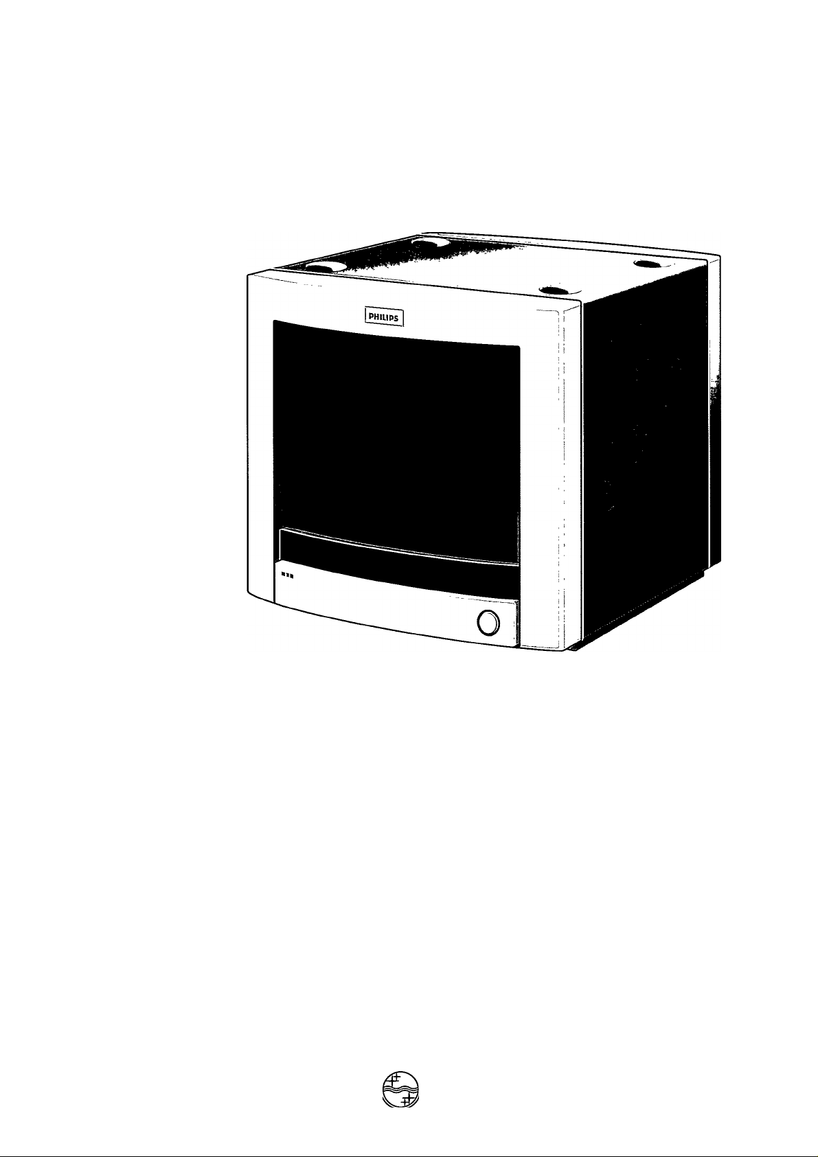
Video Colour Monitor VSS9451
Q 0 0 0 0 II
8 6
Instructions for use
(T) Mode d'emploi
® Bedienungsanleitung
® Gebruiksaanwijzing
d) Instrucciones de manejo
(T) Instruzzioni per l'uso
PHILIPS
PHILIPS
Page 2

English.........................................................................page 3
CE) Français
..........................................................................
page 6
CD Deutsch...........................................................................Seite 8
Nederlands
...............................................................
pagina 10
CD Espanol......................................................................pagina 12
CD Italiano........................................................................pagina 14
Bescheinigung des
Herstellers/Importeurs
Hiermit wird bescheinigt, daß der
VSS9451/00T
(Gerät, Typ Bezeichnung)
in Übereinstimmung mit den Bestimmungen der BMPT-AmtsbIVfg243/1991 funk
entstört ist. Der vorschriftsmäßige Betrieb mancher Geräte (z. B. Meßsender) kann
allerdings gewissen Einschränkungen unterliegen. Beachten Sie deshalb die Hinweise
in der Bedienungs-anleitung.
Dem Bundesamt für die Zulassungen in der Telekommunikation wurde das In
verkehrbringen dieses Gerätes angezeigt und die Berechtigung zur Überprüfung der
Serie auf die Einhaltung der Bestimmungen eingeräumt.
Philips GmBH Hamburg
(Name und Anschrift des Herstellers/Importeurs)
Page 3

INSTRUCTIONS FOR USE @)
a>
c
LU
Volume
Hue Saturation Contrast Brightness Horizontal
a
CONTROLS
1 Volume.
To adjust the volume.
2 Huer-^
3 Picture controls
- Saturation @
- Contrast 3
- Brightness
4 Horizontal shift
5 Power
------ (NTSC versions only)
To adjust the hue.
To optimize the picture. The centre click position of each
control is its standard setting.
To adjust the colour density of the picture.
To adjust the picture contrast.
To adjust the picture brightness.
Screwdriver adjustment to center the picture. The factory
dafault is optimized for standard video signals.
Switching the power on and off.
Shift
O
C3^
FITTING A MAINS PLUG {U.K. only)
This apparatus is fitted with an approved moulded 13 Amp plug.
To change a fuse in this type of plug proceed as follows:
1. Remove fuse cover and fuse.
2. Insert new fuse, which should be a BS1362 5A, A.S.T.A. or
BSI-approved type.
3. Refit the fuse cover.
If the fitted plug is not suitable for your
socket outlets, it should be cut off and
an appropriate plug fitted in its place.
If the mains plug contains a fuse, this
should have a value of 5A.
If a plug without a fuse is used, the fuse
at the distribution board
should not be greater than 5A.
NOTE: The severed plug must be disposed of to avoid the
possibility of an electric shock should it be inserted into a 13A
socket elsewhere.
HOW TO CONNECT A PLUG
The wires in the mains lead are coloured in accordance with
the following code:
BLUE-“NEUTRAL" ("N”)
BROWN - "LIVE" ("L")
GREEN & YELLOW - "EARTH" ("E")
1. The GREEN AND YELLOW wire must be connected to the
terminal in the plug which is marked by the letter "E" or by
the safety earth symbol i or coloured GREEN or GREEN
AND YELLOW.
2. The BLUE wire must be connected to the terminal which is
marked with the letter "N" or coloured BLACK.
3. The BROWN wire must be connected to the terminal which
is marked with the letter "L" or coloured RED.
Before replacing the plug cover, make certain that the cord
grip is clamped over the sheath of the lead - not simply over
the three wires.
Page 4

(|b) instructions for use
PRECAUTIONS
m
3
In order to prevent any fatal accidents caused by misoperation
(Q_
or mishandling of the monitor, be fully aware of all the
55'
following precautions:
3"
• Only use the power source specified on the rating label
located on the of the cabinet.
• When not using this unit for a long period of time, or when
cleaning it, be sure to disconnect the mains plug from the
mains supply.
• Do not allow anything to rest on the mains lead.
• Do not locate this unit where people will tread on the cord.
• Do not overload wall sockets or mains leads as this may
result in fire or electric shock.
• Avoid using this unit under the following conditions;
- in extremely hot, cold or humid places;
- in dusty places;
- near appliances generating strong magnetic fields;
- in places subject to direct sunlight;
- in badly ventilated places.
• Do not cover the ventilation slots while in operation as this
could obstruct the required ventilation.
• When dust accumulates on the screen surface, clean with a
soft cloth.
• Do not use alcohol or ammonia based liquid to clean the
monitor.
If necessary, clean with a slightly damp cloth. Disconnect
the monitor from the mains supply before cleaning.
• Unplug this unit from the wall socket and refer servicing to
qualified service personnel under the following conditions:
- when the mains lead is frayed or the plug is damaged;
- if liquid has been spilled into the unit;
- if the unit does not operate normally following the
operating instructions;
- if the unit has been dropped or the cabinet has been
damaged;
- when the unit exhibits a distinct change in performance.
• Do not attempt to service this unit yourself as opening or
removing covers may expose you to dangerous voltage or
other hazards. Always refer servicing to qualified service
personnel.
INSTALLATION
' Before installing this monitor, please refer to the instructions
for use of your camera or VCR to make sure if
these equipments require any change of setting.
POSITIONING/VENTILATION
When positioning this equipment ensure that the mains plug
and socket are easily accessible.
Do not place the monitor near a heat source.
To prevent overheating, ensure that the ventilation openings
of the monitor are not covered.
MAINS CONNECTIONS
Before connecting the equipment to the mains of the
building installation, the protective earth lead of the building
must be checked for its proper functioning.
The monitor is supplied with a 2 m. long mains lead
terminated with a 2-pole Europlug with safety earth
connections. In some countries it will be necessary to
replace this plug with one of a locally standard type. The
wiring to the plug must be as follows:
brown - live (in the U.K. marked °L° or coloured red);
blue - neutral (in the U.K. marked °N” or coloured black);
yellow/green - earth (in the U.K. marked “E° or i or coloured
yellow and green).
VIDEO/AUDIO INPUT
Be sure to disconnect the mains lead from the mains socket
before connecting the other equipment.
Also refer to the instructions for use of the equipment to be
connected.
WARNINGS
- To prevent fire or shock hazard, do not expose this
monitor to rain or moisture.
- Dangerous high voltages are present inside the unit. Do
not remove the back cover of the cabinet.
- When servicing the monitor, contact qualified service
personnel. Never try to service it yourself.
- Improper operations, in particular alteration of high
voltage or changing the type of tube may result in x-ray
emission of considerable dose.
A unit altered in such a way no longer meets the
standards of certification, and must therefore no longer
be operated.
Page 5

INSTRUCTIONS FOR USE @)
CONNECTIONS
-€» O
76û H.gh \ J
1 POWER
• Connect to the mains socket using the mains lead supplied.
2 CVBS
•© - Input socket for composite video signal.
• Connect to e.g. a video camera, VCR or video control panel.
G» - Output socket for signal loopthrough to other equipment.
• Connect to e.g. a second monitor or VCR.
3 Audio
■© - Input socket for audio signal.
• Connect to e.g. an audio control panel or amplifier.
G» - Output socket for signal loopthrough to other equipment.
• Connect to e.g. a second monitor or VCR.
4 75 0-High
Signal line termination switch for CVBS in- outputs.
• Switch to 75 O when there is only input signal.
• Switch to High in case of loopthrough operation.
5 Y/C Input
Input socket for luminance (Y) and chrominance (C) signal.
This input can be used in applications where high resolution
is required.
Socket and signals according to S-VHS standard.
1 GND (luminance)
2 GND (chrominance)
3 LUMINANCE signal
4 CHROMINANCE signal
TECHNICAL DATA
a. Electrical
Picture tube:
Resolution:
Signal inputs:
- CVBS:
..................................
.................................
....................................
14°, 90° deflection, 0.42 mm
> 520 TVL (bandwith 6.5 MHz)
1 Vpp into 75 Q or bridging/BNC
- Y/C:...................1 Vpp/300mVpp into 75 Q/Hosiden {MINI DIN)
-Audio:
....................................................................
177mVeff into 10 K Ì2
TV standard:..............................................PAL, 625 lines, 50 Hz
Power supply:
...................
mains voltage 198 -264 V AC / 50 Hz
b. Environmental
Temperature range:...........................operating: + 10 to + 40° C
.............................................................storage: - 25 to + 70° C
Humidity:
......................................
20% - 95% (non condensing)
Subject to modification.
s:
_<2
"o)
c
HI
6 Notch Off
To avoid cross colour interference when using the CVBS
input (2).
In high resolution Y/C operation this switch should preferably
be set to off.
NOTE!
Never use the CVBS (2) and the Y/C (5) connection at the
same time.
Page 6

PlaceringA'entilation
Paikka/llmankierto
VARNING:
FÓRSÀKRA DIG OM ATT HUVUDBRYTARE OCR
UTTAG ÀR LATATKOMLIGA, NAR DU STÀLLER DIN
UTRUSTNINGPÀPLATS.
Placering/ventilation
ADVARSEL:
S0RG VED PLACERINGEN FOR, AT
NETLEDNINGENSSTIK OG STIKKONTAKTER NEMT
TILG/ENGELIGE.
MUY IMPORTANTE
La tapa posterior unicamente debe retirarla un Técnico
de Servicio.
La puesta en funcionamiento del aparato sin tapa
posterior es peligrosísimo.
VAROITUS:
SIJOITA LAITE SITEN, ETTA VERKKOJOHTO
VOIDAAN TARVITTAESSAHELPOSTIIRROTTAA
PISTORASIASTA.
PlasseringA/entilasjon
ADVARSEL:
NÁR DETTE UTSTYRET PLASSERES, MÀ DU PASSE
PÁ AT KONTAKTENE FOR ST0MTILF0RSEL ER
LETTE ANÀ.
3138 105 28281
0693/1
 Loading...