

Page 1

2
GB
RS232 Control Box
Table of contents
Page
Introduction ............................................................ 4
Installation ..............................................................5
Mounting the box
System cable
External power supply
Location of switches and connectors
Internal switch settings.............................................8
Possible configurations ............................................9
Technical specifications .........................................11
Read these instructions, before putting your system in operation
Page 2

3
GB
Electro Magnetic Compatibility (EMC)
This equipment complies with European rules for EMC according to
EN55022 and EN50082-1.
Operation is subject to the following two conditions:
1 This device may not cause harmful interference.
2 This device must accept any interference received, including
interference that may cause undesired operation.
The equipment conforms with the EMC directive and low-voltage
directive.
This device complies to FCC rules under test conditions that included
use of system cables and connectors between system components. If
you have any problems, contact your dealer.
Warnings
Any unauthorized modification to this equipment may cause violation
of the FCC rules resulting in the revocation of the authorization to
operate the equipment.
To prevent fire or shock hazard, do not expose this accessory to rain or
moisture.
The exclamation mark within a triangle is intended to alert the
user to the presence of important operating and maintenance
(servicing) instructions in the literature accompanying the
appliance.
Note: We advise you to use the following types of mains power
adapters in combination with the camera:
UK Philips VCM1162/01R
EUR Philips VCM1162/00R
US Philips VC11625R (UL listed)
Page 3
4
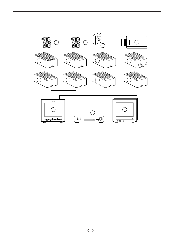
Introduction
Thank you for buying this accessory for your observation system.
1 System monitor
2 Video recorder (VCR)
3 Slave monitor
4 Accessory boxes (0-2 per cable)
5 Interface box
6 System cameras
7 Non system cameras (CVBS)
8 Mains power adapter
The following items are included in this kit:
1 RS232 control box
1 System cable (5m/15ft)
1 User manual
1 RS232 cable
1 Power supply
GB
>
N
<
E
R
A
A
R
F
6 6
4
4 4
1
Colour Observation system
_
talkaction menu
view
+ next
auto
>
N
<
E
R
A
A
R
F
8
4
4
4
2
Colour Observation Monitor
7
5
4
3
Colour Observation Monitor
Page 4

5
The RS232 Control Box allows the user to control the Observation
System from another location or through a PC. With the right
additional equipment, this accessory allows the user to perform most
functions of the Observation system (switching to other camera or
view mode, action command etc.). In addition, it has a local standard
video and audio output from the system monitor, and provides a local
alarm relay output.
Applications include remote video transmission and system control
(specific third party equipment needed) and PC control of system
modes.
Installation
Remark: When the system configuration is altered, the system monitor
needs to check and memorise the configuration of the cameras and
accessories connected to its inputs. This is done automatically when
the power is switched on. Use the power switch to switch off; only
operating the power save key is not sufficient. If switching off is
impracticable, use the auto install option of the system monitor's install
menu.
Power on sequence:
First power on the RS232 control box and then the Observation
System.
GB
Page 5

6
Mounting the box
1 Loosen the screw holding the cover and remove the cover.
2 Remove the circuit board
3 Fasten the bottom plate of the box with two screws.
4 Fit the circuit board.
5 IMPORTANT: Adjust the settings of the circuit board switches to
configure the box according to your system. See section 'settings'.
6 Fit the cover and secure the screw holding it.
7 Now make the connections. See section 'possible configurations'
for the correct connections and the setting of the internal 'slide
switches'.
GB
Page 6

7
System cable
For the interconnections between the monitor, accessories and camera,
a system cable is supplied. For an optimum picture and sound quality,
you should always use 4-wire dual twisted-pair cable when extending
the connection (max. 300m/900ft). The cable and plugs are available in
the hobby and professional trade. Fix the connectors to the cable
corresponding to the f igure below.
Caution: The plugs used for the observation system have the same
dimensions as standard telephone plugs.
Never connect the security system with telephone equipment!
External power supply
The box needs to be powered locally with a mains power supply which
is included in the product.
GB
5
4
5
4
3
2
5
4
3
2
5
4
3
2
4-5
2-3
3
2
4-5
2-3
Page 7
8
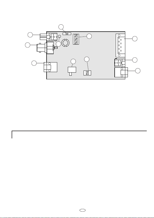
Location of the switches and connectors
1. Audio output
2. Video output
3. System cable output (connect to optional slave monitor)
4. Status LED
5. Alarm output screw block
6. Slide switch (slave or no slave)
7. Dip switches (slave or no slave)
8. RS232 connector (D-9, male)
9. DC power input for mains power supply
10. System cable input (connect to system monitor slave output)
11. Audio level switch (high or low)
Internal switch settings
Slave in line switch (6, 7)
With these switch you can enable a slave monitor on the system cable
output of the RS232 Control Box.
There are two possibilities:
• No slave
There is no slave monitor connected after the RS232 Control Box
(seen from the system monitor)
• Slave
There is a slave monitor connected after the RS232 Control Box (seen
from the system monitor)
Audio level switch (11)
With this switch the audio output level can be selected. There are two
possibilities: High and Low level.
Remark: The slave in line switch is normally set to the "NO SLAVE"
position.
GB
11
1
2
4
5
8
7
3
6
9
10
Page 8
9
Possible configurations
This section shows the system configurations which are possible with
the RS232 Control Box.
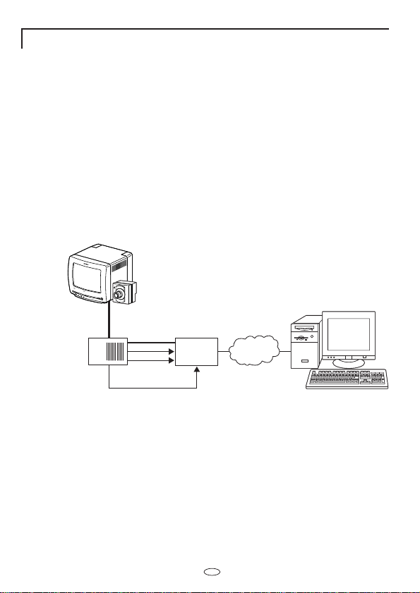
1. Remote video transmission with control capabilities (third
party equipement needed)
The Observation System can be connected to a video transmission unit
for off-site viewing of the system video. When using the RS232
Control Box with selected third party video transmission equipement,
the Observation System can also be controlled from the remote site,
allowing the user to switch to different cameras and perform local
actions like opening doors.
Remark: For this application the video transmission unit needs to
support the Philips RS232 Control Protocol.
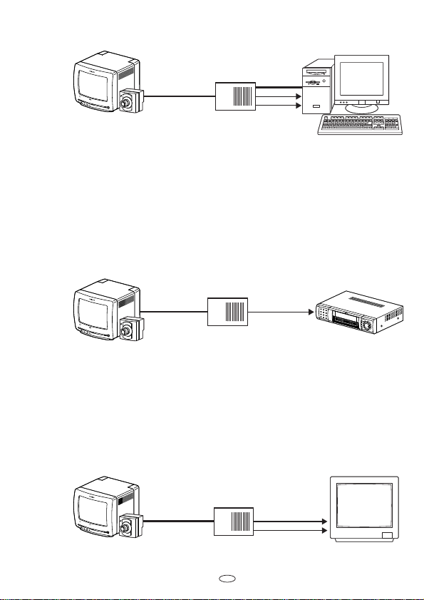
2. Using PC as slave monitor with control capabilities (third
party software needed)
The Observation System can connect directly to a PC for control and
display. The RS232 interface of the RS232 Control Box can connect to
the serial port of a PC for control of the Observation System.
For also displaying the system video on the PC, a PC with a analogue
video input (video grabber board) is needed.
When the appropriate software is loaded on the PC, the video and
audio of the Observation System can be shown on the screen and the
functionality of the system can be partly controlled.
Remark: For this application specific third party software is needed
GB
Colour Observation Monitor
RS232
Control
Box
System
cable
Observation System
video transmission
RS232
Local audio
and video
Alarm
Third party
Multimedia PC with modem
product
Network
Page 9
10
3. Additional alarm output with short activation time
The Observation System has an alarm output (on the back of the
monitor) with a long activation time (typically 15 minutes, see system
user manual). For some applications this can be too long. The alarm
output activation time of the RS232 Control Box is 30 seconds,
solving the problem in most cases.
4. Connecting a standard monitor as slave monitor
Using the video and audio outputs on the RS232 Control Box, a
standard video monitor or TV can be used as a slave monitor output,
while still having the advantage of using the system cable to cover
large distances.
GB
Observation System
Colour Observation Monitor
System slave output
System cable
Up to 200 meters
RS232
Control
and video to
PC grabber card
Multimedia PC with video input
RS232
Local audio
Observation System
System cable
Colour Observation Monitor
System slave output
RS232
Control
Alarm cable
2 wire
Time lapse VCR
TL720R
Observation System Standard TV or monitor
RS232
Colour Observation Monitor
System slave output
System cable
Up to 200 meters
Control
Local audio
and video
Page 10

11
GB
Technical specifications
TV standard both PAL and NTSC
Power supply External mains power supply (24 VDC)
Power consumption 150 mA
System connectors RJ11E modular ("telephone" connectors)
System cable 4-wire dual twisted-pair telephone cable
System input RJ11E system input from system slave
output
Slave monitor output RJ11E system output
Control port 9 pin D-Sub male, RS232 at 9600 bps,
8 bits, no parity, 1 stop bit
Auxiliary outputs
• audio output Cinch from system camera input
High level: 500m Vpp, 1kOhm
Low level: 10mVpp, 10kOhm
• video output BNC (1 Vpp, 75 Ohm) from system camera
input
• alarm output 3 pole internal screw block with normally
open and normally closed contacts (contact
rating 30 V, 5 A AC/DC, activation time
30 seconds)
Weight 170 gr. (exclusive mains power supply)
Dimensions (hxwxd) 119 x 77 x 42 mm
Ambient temperature
• operating -5...+55°C
• storage -25...+70°C
Ambient humidity 20...98 %RH
Specifications may change without notice.
RS232 connector pin out
1. N.C.
2. Transmit data (Txd)
3. Receive data (Rxd)
4. N.C.
5. Ground (GND)
6. N.C.
7. Connected to pin 8
8. Connected to pin 7
9. N.C.
5 4 3 2 1
9 8 7 6
 Loading...